Acrosser Technology AIV-HM76V0FL Series User manual

AIV-HM76V0FL
User Manual
1

Copyright
All Rights Reserved.
Manual’s first edition:
For the purpose of improving reliability, design and function, the
information in this document is subject to change without prior notice and
does not represent a commitment on the part of the manufacturer.
In no event will the manufacturer be liable for direct, indirect, special,
incidental, or consequential damages arising out of the use or inability to use
the product or documentation, even if advised of the possibility of such
damages.
This document contains proprietary information protected by copyright. All
rights are reserved. No part of this Manual may be reproduced by any
mechanical, electronic, or other means in any form without prior written
permission of the manufacturer.
Trademarks
AIV-HM76V0FL are registered trademarks of Acrosser; IBM PC is a registered
trademark of the International Business Machines Corporation; Pentium is a
registered trademark of Intel Technologies Inc; AMI is a registered trademark of
AMI Software International Inc; other product names mentioned herein are used
for identification purposes only and may be trademarks and/or registered
trademarks of their respective companies.
2

Table of Contents
Chapter 1 System Introduction............................................................................................5
1.1 ...............................................................................................5Specifications
1.2 .................................................................................................6Packing List
1.3 ........................................................................................................6Features
1.4 ........................................................................................7System Dissection
Chapter 2 Procedures of Assembly/Disassembly..............................................................10
2.1 .................................................................................102.5”HDD Installation
2.2 ...................................................................................14CF Card Installation
2.3. .................................................................................17SIM Card Installation
2.4 ...................................................................................20Antenna Installation
Chapter 3 Introduction.......................................................................................................22
3.1 .............................................................................................22Specifications
3.2 .......................................................................................23Package Contents
3.3 ...........................................................................................23Block Diagram
Chapter 4 H/W Information...............................................................................................24
4.1 ...............................................................24Mainboard illustration(Top Side)
4.2 ..............................25Locations of IO ports & Jumper settings definition
Chapter 5 BIOS Settings....................................................................................................35
5.1. .................................................................................................36Main Setup
5.2. ............................................................................39Advanced Chipset Setup
5.3. .............................................................................................48Chipset Setup
5.4. ..................................................................................................53Boot Setup
5.5. .............................................................................................54Security setup
5.6. ......................................................................................55Save & Exit Setup
Chapter 6 Function Description.........................................................................................57
6.1 ..............................................................................57Power input connection
6.2 .............................................................................................57Digital Inputs
6.3 ...........................................................................................59Digital Outputs
6.4 .........................................................................................60Watchdog Timer
6.5 ..............................................................................................60RS-232 Ports
6.6 .....................................................................................62Serial ATA (SATA)
6.7 ............................................................................................................62USB
Chapter 7 Driver And Utility Installation..........................................................................63
7.1 ..........................................................63Introduction to Driver CD Interface
7.2 ..................................................77Windows 7 32 / 64 bit Driver Installation
3

Chapter 8 Software Installation and Programming Guide.................................................84
8.1. .....................................................................................................84CAN bus
8.2. ................................................................................85CAN Message Format
8.3. ..................................................................................87GPIO and Watchdog
8.4. .......................................................................................88Power Subsystem
8.5. .......................................................................................89I-Button Function
8.6. ..........................................................................90API List and Descriptions
Appendix A......................................................................................................................106
Appendix B: GPIO cable color........................................................................................107
4

Chapter 1 System Introduction
AIV-HM76V0FL Series with Intel 3rd generation Core i3/i5/ i7 processor is a
multi-function In-Vehicle computer, which is suitable for using in all kind of
applications. Besides basic I/O ports like VGA, LVDS, HDMI, DVI, Hybrid Multiple
Display, USB, COM. LAN, and GPIO, AIV-HM76V0FL has complete wireless
solutions for GPS / 3.5G / WiFi / Bluetooth selection, Video capture, Swappable
2.5” HDD, DC output, Driver ID, and embedded CAN Bus function to allow
micro-controllers and devices to communicate with each other in vehicle. In
addition, AIV-HM76V0FL has intelligent power management function with
software utility to monitor power status and control power sequence, and also
compliant with most industry standards for in-vehicle usage including CE, FCC,
and E-Mark.
1.1 Specifications
Support Intel 3rd generation Core i3/ i5/i7 CPU + HM76 chipset
DDR3 SO-DIMM * 2, up to16GB memory
Display --- VGA + HDMI + DVI
Combo connector --- VGA +Audio + USB + DC power
SATA x 2 & SATA power x 2
Swappable Anti-Shock 2.5” HDD bay x 1
Intel GbE chip LAN x 2
COM x 3 (2 x connector & 1 x pin header)
CF type II socket x 1 / SIM slot x 1
Audio connector (MIC & Line-out)
Mini PCIe socket x 2 (Capable for WiFi / 3.5G)
GPIO ports (8) & CAN bus
Driver ID (Use I-Button) can certified driver,
9 ~ 32V DC input & customer define power management mode for ODM
12V DC 20W output connector for monitor
5

1.2 Packing List
Check if the following items are included in the package.
AIV-HM76V0FL x1
User Guide & System Driver CD x 1
Screw pack(2.5”HDD bracket: 4pcs) x 1
Terminal block female 3pin x 1
Spare Fuse 10A x 1
SATA & SATA power cable x 1
Remote Switch Cable x 1
GPIO/CAN/Driver ID DB15 Connector x 1
1.3 Features
Rugged fanless design
Support Intel 3rd generation Core i3/ i5/i7 CPU + HM76 chipset
2 * DDR3 SO-DIMM, up to 16GB
Support CAN 2.0A/2.0B protocol and I-Button for driver ID
VGA/HDMI/ DVI-I output
Variety Wireless Communication
Combo connector to simplify touch monitor installation
6
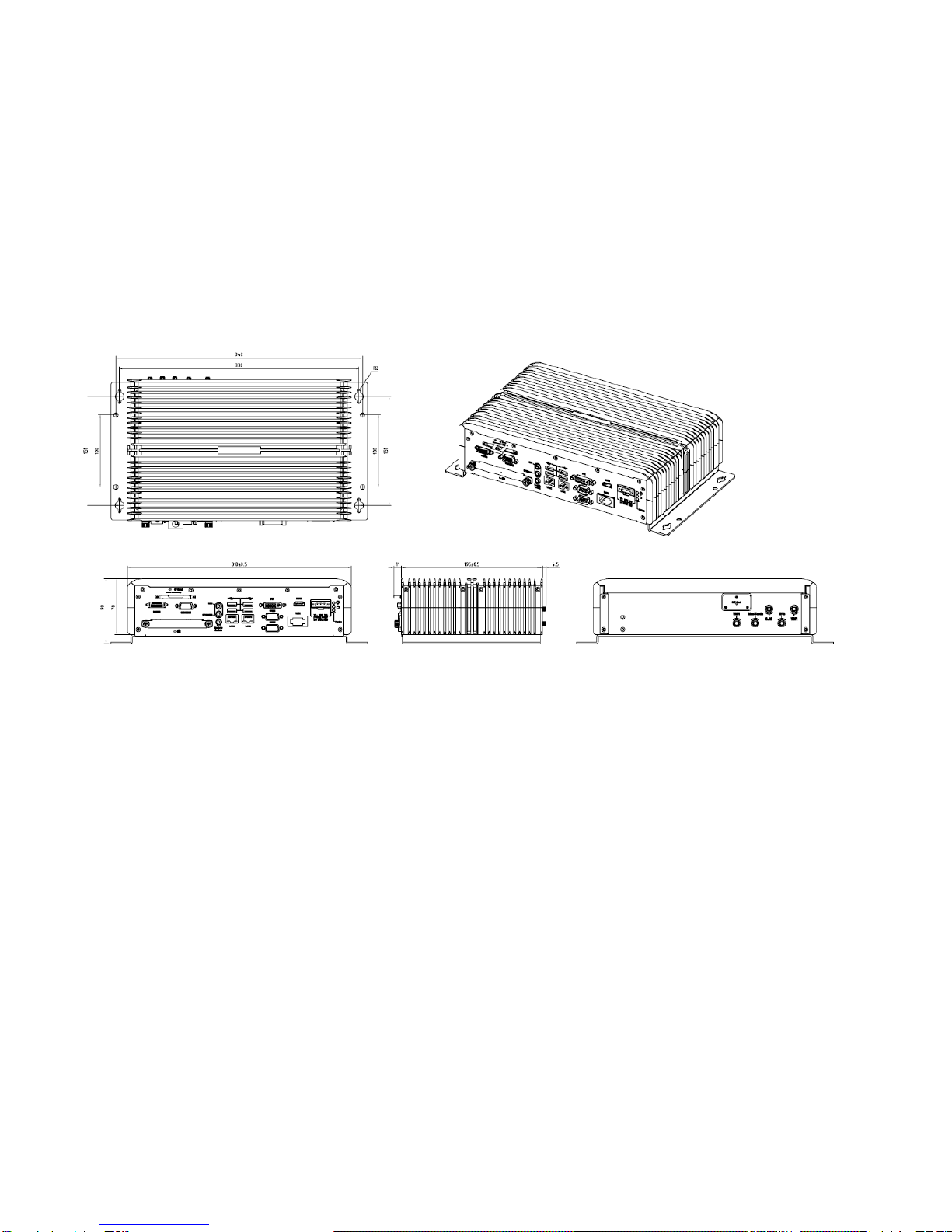
1.4 System Dissection
1.4.1 Dimensions
7

1.4.2 I/O Panel
FRONT IO & PRINT
Rear I/O & PRINT
8

1.4.3 System Configuration
8
6
7
5
4
2
1
3
Item Description Quantity
1 DDR3 module 1
2 GPS & Bluetooth module 1
3 AIV-HM76V0FL main board 1
4 Module Heat-Spreader 1
5 SIM card connector 1
6 Wi-Fi & 3.5G module 1
7 CF Bracket 1
8 HDD Bracket 1
9
Chapter 2 Procedures of
Assembly/Disassembly
2.1 2.5”HDD Installation
The following instructions will guide you to install HDD step-by-step.
2.1.1 Unfasten the screw of chassis.
UNSCREW
10

2.1.2 Open the bracket.
Assemble HDD into bracket by fastening 4 screws.
11

12
2.1.3 Assemble the HDD bracket back to system.
Finish.
SCREW
13

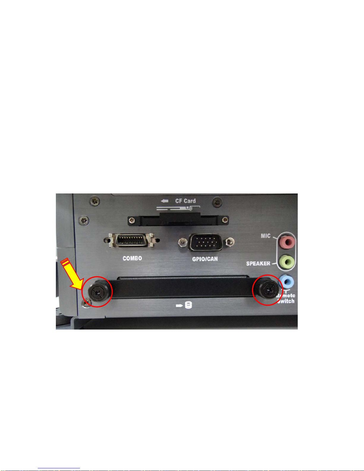
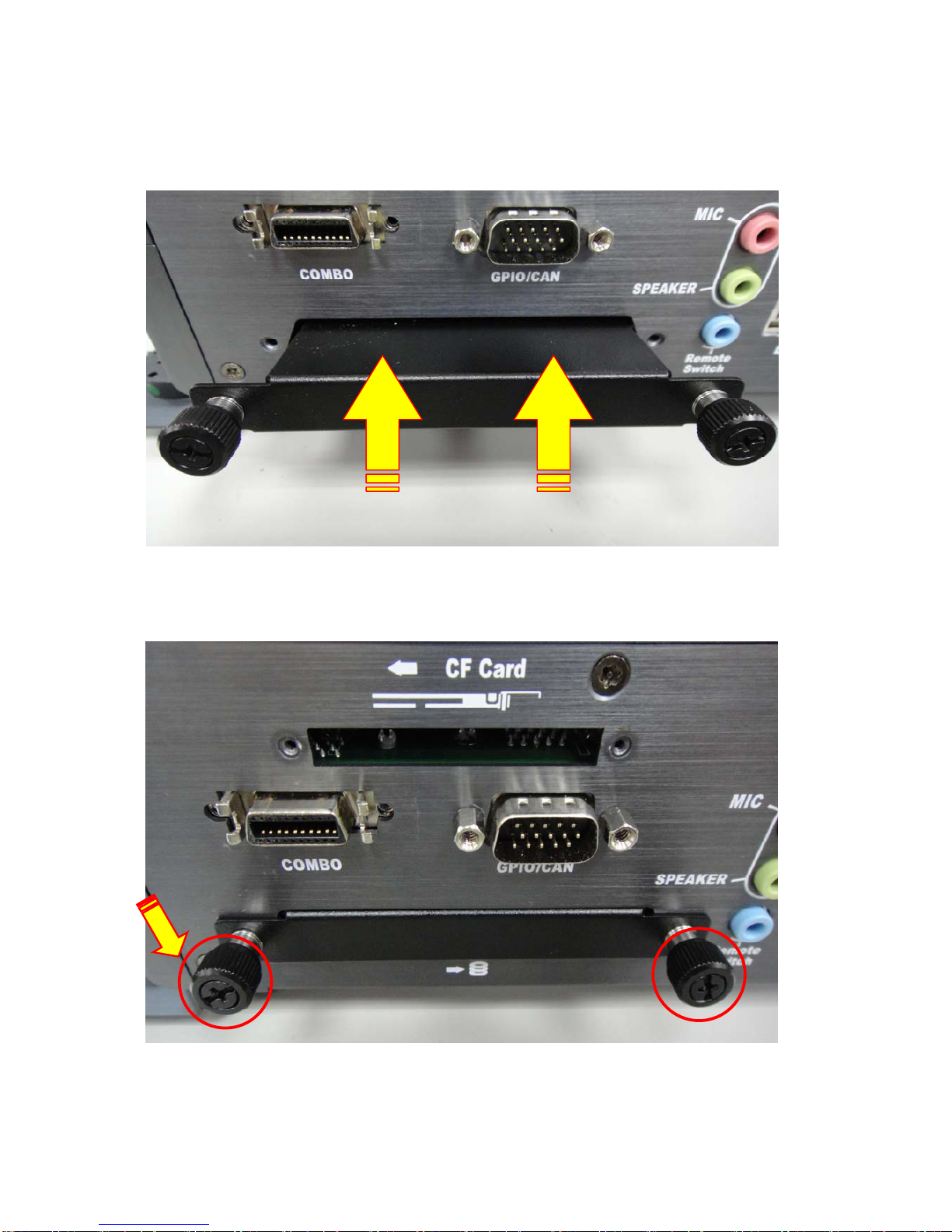
2.2 CF Card Installation
2.2.1. Unfasten the 2 screws and pull the CF bracket
from I/O panel.
14
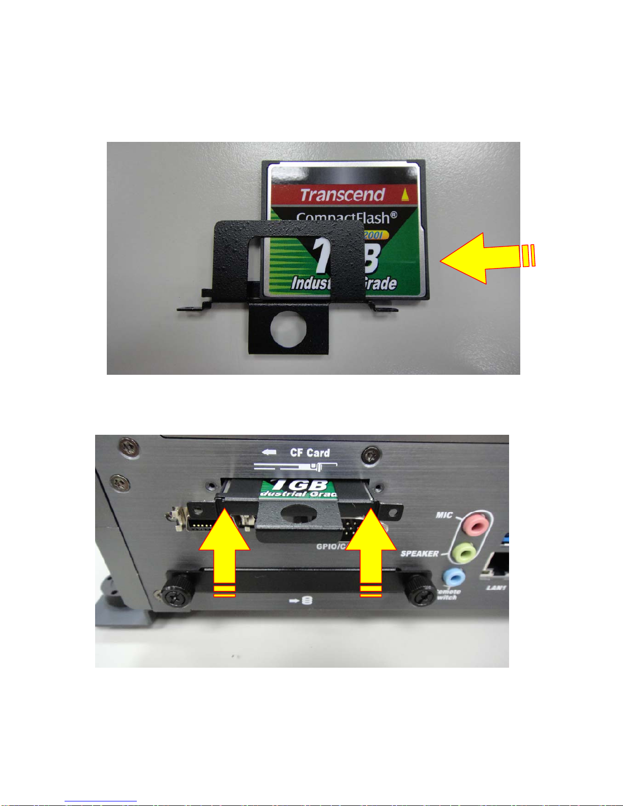
2.2.2. Assemble the CF card with CF bracket.
The direction for
installing the CF card
15

Finish.
16
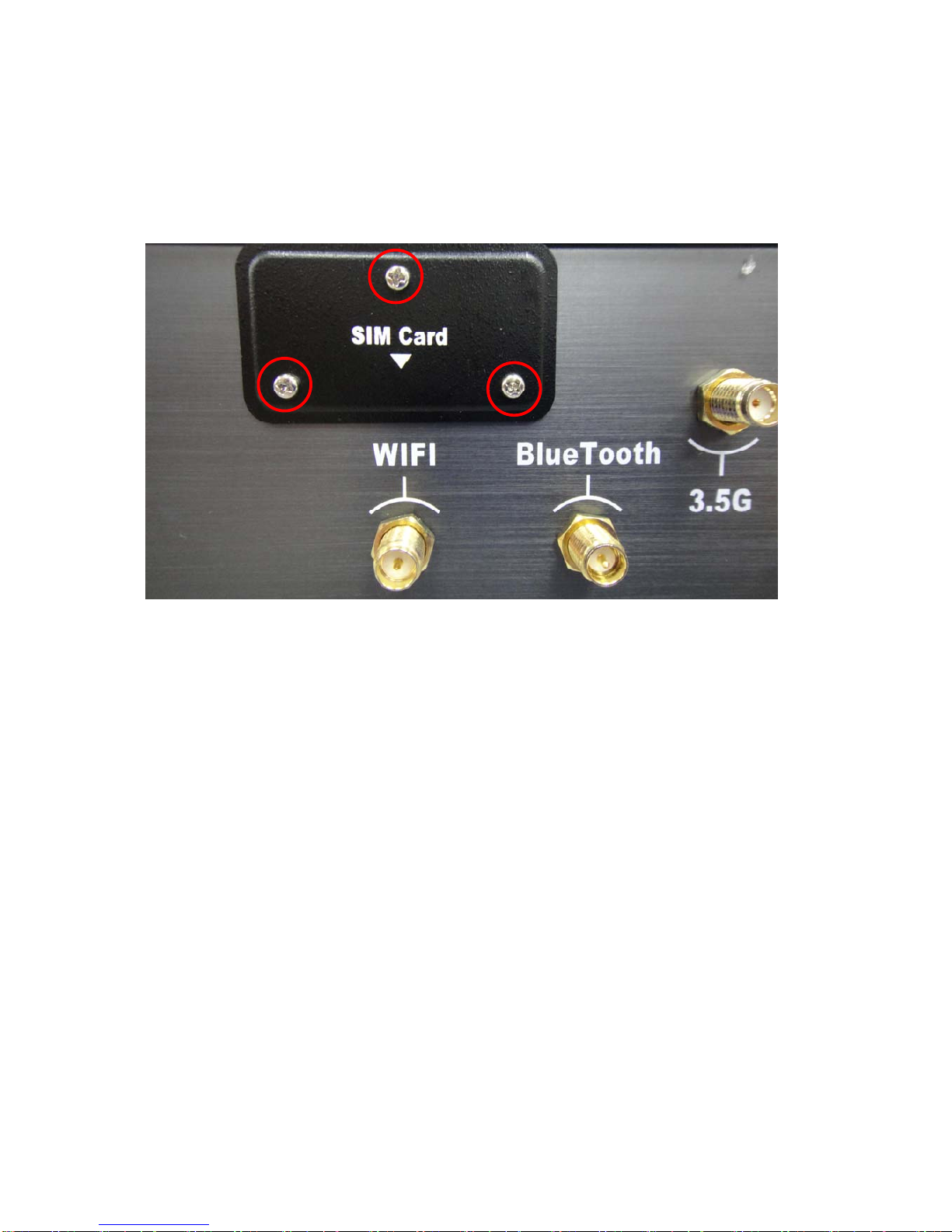
2.3. SIM Card Installation
2.3.1. Unfasten the 3 screws from Rear I/O panel.
17

2.3.2. Insert SIM card.
Step1.
Step2.
18

Finish.
19

2.4 Antenna Installation
Tack out antenna from packing bag and install.
20
Table of contents
Other Acrosser Technology Automobile Accessories manuals

Acrosser Technology
Acrosser Technology AIV-HM76V1FLCi3 User manual

Acrosser Technology
Acrosser Technology AR-B6005 User manual

Acrosser Technology
Acrosser Technology AIV-QM97V1FL Series User manual

Acrosser Technology
Acrosser Technology AR-B1896 User manual

Acrosser Technology
Acrosser Technology AR-V6002FL User manual
Popular Automobile Accessories manuals by other brands


Tuff Tonneaus
Tuff Tonneaus 142 FITTING INSTRUCTION

Soundoff Signal
Soundoff Signal Mpower EMPSC07M Series installation instructions

Bosch
Bosch USB CM-Hub operating instructions

Medion
Medion MD 85722 manual

FABBRI PORTATUTTO
FABBRI PORTATUTTO 17523000 Assembly instructions

Intellitronix
Intellitronix DP9002 installation guide


