manuals.online logo
Brands
  1. Home
  2. •
  3. Brands
  4. •
  5. Fortin
  6. •
  7. Automobile Accessories
  8. •
  9. Fortin EVO-ALL User manual

Fortin EVO-ALL User manual

Service No : 000 102 04 2536
Hardware Ver: x
Firmware Ver: x.x
Date: xx-xx
INTERFACE MODULE
Made in Canada
PATENTS PENDING US: 2007-228827-A1
www.fortinbypass.com
HARDWARE VERSION
FIRMWARE VERSION
Module label | Étiquette sur le module
Install guide and
addemdum guide updates
are posted to the web on a
regular basis. We recommend
you check for install guide
updates prior to installation of
thisproduct.
Desmisesàjourdecemanuel
et des addendas sont mises en
ligne régulièrement. Vérifiez
que vous avez bien la dernière
versionavantl'installation.
Firmware updates are posted to the web
on a regular basis. We recommend you
check for firmware updates prior to
installationofthisproduct.
Des mises à jour Microprogramme de ce
module sont mises en ligne régulièrement.
Vérifiez que vous avez bien la dernière
versionavantl'installation.
Update Alert:Update Alert:
EVO-ALL
EVO-ALL
ADDEMDUM
EVO-ALL
EVO-ALL
TECH SUPPORT
Tél: 514-255-HELP (4357)
1-877-336-7797
WEB UPDATE | MISE À JOUR INTERNET
www.fortinbypass.com
VEHICLEVEHICULES
YEARS
ANNÉES
Connection
Programming
Lock
Unlock
Arm
Disarm
Trunk/Hatch
Tachometer
A
ctivateOEMrem
o
start
Start/Stopcontrol
Doorstatus
TrunkStatus
HoodTrigger
RAPDisable
TransponderBypas
PK3,Passlock
Slidingdoor*
Defrost
Heatseats
GasDoor
WindowRollDown
HatchTrigger
FootBrakeSignal
ParkingLight
HandBrakeSignal
RearDefrost
HeatedMirrors
MemoryDriver
Keycontrol
SUBARU ABCDEF G HI JKLMNOPQRSTUVWXYZZ1
Forester 2008Ͳ2010 39 7 •••• • •• •
Im
p
reza 2008Ͳ201
0
39 7 •••• • •• •
Legacy 2005Ͳ2009 39 7 •••• • ••
Legacy 2010 39 7 •••• • •• • •
Outbac
k
2005Ͳ200
9
39 7 •••• • •• •
Outbac
k
2010 39 7 •••• • •• • •
Tribeca 2006Ͳ200
9
39 7 •••• • ••
SUBARU
Rev : A - 22042010
ADDEMDUMS GUIDE
Lock
Unlock
Arm
Disarm
Trunk/Hatch
Tachometer
A
ctivateOEMrem
o
start
Start/Stopcontrol
Doorstatus
TrunkStatus
HoodTrigger
RAPDisable
TransponderBypas
PK3,Passlock
Slidingdoor*
Defrost
Heatseats
GasDoor
WindowRollDown
HatchTrigger
FootBrakeSignal
ParkingLight
HandBrakeSignal
RearDefrost
HeatedMirrors
MemoryDriver
Keycontrol
ABCDEF G HI JKLMNOPQRSTUVWXYZZ1
•••• • •• •
•••• • •• •
•••• • ••
•••• • •• • •
•••• • •• •
•••• • •• • •
•••• • ••
INSTALLATION / PROGRAMMING PROCEDURE | P
ROCÉDURE INSTALLATION / PROGRAMMATION
1
Sélectionnez le type de
connections avec le
démarreur à distance /
alarme:
Select the type of
connection compatible with
the remote starter / Alarm:
2
Faire les branchements au
véhicule:
Make the connections to
the vehicle:
Remote
Starter/Alarm
Démarreur à
distance/alarme
4 PIN
INSTALLATION WITH DATA-LINK
INSTALLATION AVEC DATA-LlNK
THIS TYPE OF CONNECTION REQUIRED A
COMPATIBLE FORTIN DATA-LINK PROTOCOLE
ON THE REMOTE STARTER /ALARM. (Consult the
Remote starter Install guide) |
CE TYPE DE
BRANCHEMENTSREQUIÈREUNDÉMARREURÀ
DISTANCE / ALARME PROTOCOLE DATA-LINK
FORTIN COMPATIBLE. (Consultez le guide
d'installationdudémarreuràdistance)
If your using a cable between the module and
the remote car starter / Alarm: its Data-Link
mode connection. |
Si vous utilisez un câble
entre le module et le démarreur à distance /
alarme:c'estlemodeData-Link.
Red | Rouge +12V
Black | Noir Ground
CONN.1
20 PIN 4 PIN
If your using connection between the module and the remote car
starter / Alarm with this cable: its NOT Data-Link mode connection.
Si vous utilisez les branchements entre le module et le démarreur à
distance/alarmeavecsecâble:cen'estpaslemodeleData-Link.
INSTALLATION WITHOUT DATA-LINK
INSTALLATION SANS DATA-LlNK
THIS TYPE OF CONNECTION IS COMPATIBLE WITH EVERY REMOTE
STARTER / ALARM BUT MORE CONNECTIONS IS REQUIRED. |
CE TYPE
DE BRANCHEMENTS EST COMPATIBLEAVEC TOUS LES DÉMARREURS
ÀDISTANCE/ALARMEMAISREQUIÈREPLUSDEBRANCHEMENTS.
Cut off one plug of the 4 Pin
Data-Link connector
Connect the Red wire to +12V
Connect the Black wire to
Ground
1
2
3
Coupez l'extrémité du connecteur
4 pins Data-Link
Connectez le fil rouge au 12V
Connectez le fil noir à la masse
du véhicule.
1
2
3
3
PROCÉDURE DE
PROGRAMMATION
PROGRAMMING
PROCEDURE
Follow the programming
procedure on page 4. Suivez la procédure de
programmation à la page 4.
Remote
Starter/Alarm
Démarreur à
distance/alarme
20PinsConnecteur(Blanc):
Effectuezlesbranchements.
20PINConnector(White):
Maketheconnections.
5 Pins Connecteur CAN (Blanc):
Effectuez les branchements.(Si nécessaire)
5PINConnectorCAN (White):
Maketheconnections(ifrequired)
6 Pins Connecteur RELAI (Rouge):
Effectuez les branchements.(Si nécessaire)
6 PIN Connector RELAY(Red):
Make the connections (if required)
2
0
PIN
CO
NN.
5
PIN
CO
NN.
6
PIN
CO
NN.
2This Vehicle Fit Guide may change without notice. www.ifar.ca for latest version.
BCM
Yellow/Green
Yellow/Red
NC1
COMM1
N.C.
N.C.
N.C.
N.C.
Lt. Blue/Black DATA BCM
Brown/White
Yellow/Black
Hand Brake Status
Trunk
TACH Pink
n.c.
n.c.
n.c.
n.c.
n.c.
BlackBrake Status
n.c.
CAN 2 HIGH
CAN 2 LOW
Gray
Gray/Black
n.c.
n.c.
n.c.
PIN 24
PIN 9
PIN 27 PIN 26
BCM located directly below the
steering column. |
BCM situés
directement sous la colonne de
direction .
BCM
BCM located on the right side of the
steering column. |
BCM situés sur le
côté droit de la colonne de direction.
BCM
BCM located directly below
the steering column. |
BCM
situés directement sous la
colonne de direction .
Use the key
or (optionnal)
TB-SUBARU
Yellow/Green
Yellow/Red
NC1
COMM1
Yellow/Green
Yellow/Red
NC1
COMM1
Lt. Blue/Black DATA BCM
OROR
OR OR
PIN 9
PIN 1 CAN 2 HIGH
CAN 2 LOW CAN 2 HIGH
CAN 2 LOW
PIN 35
PIN 27
Forester 08-10
CANHigh Pin#1 Pink
CANLow Pin#9
LtGreen/Red
DataBCM Pin#24
Yellow/Green
Impreza 08-10
CANHigh Pin#1 Pink
CANLow Pin#9 Blue
DataBCM Pin#24Gray/Red
Legacy 05-09
Outback 05-09
Tribeca 06-09
CANHighPin#27 Pink
CANLow Pin#26 Purple
DataBCMPin#9 Yellow/Green
Legacy 10
Outback 10
CANHigh Pin#27 Red
CANLow Pin#35 Blue
DataBCM Pin#11 Yellow
PIN 11
Dk. Blue
Green
Purple/White
Purple
White Trunk Status
Doors Status
Unlock/Disarm
Lock/Arm
(-) While Running
Yellow Ignition
n.c.
n.c.
n.c.
MAKE 5 TO 10 LOOPSAROUND THE KEY.
FAIRE 5 À 10 TOURS AUTOUR DE LA CLÉ
.
MAKE 3 TO 4 LOOPSAROUND THE IGNITION
KEY BARREL.
FAIRE 3 À 4 TOURS AUTOUR DU BARRILET
D'IGNITION.
OR
OR
2
0
PIN
CO
NN.
6
PIN RED
CO
NN.
5
PIN
CO
NN.
Connect wire to vehicle
Branchement du filage au véhicule
Connect wire to Remote-Starter/Alarm
Branchement du filage au démarreur
à distance/Alarme
Connection not required with Data-link
Branchement non requis avec Data-Link
Connection always required
Branchement toujours requis
Input | Entrée
Output | Sortie
3
Ce Guide peut faire l’objet de changement sans préavis. www.ifar.ca pour la récente version.
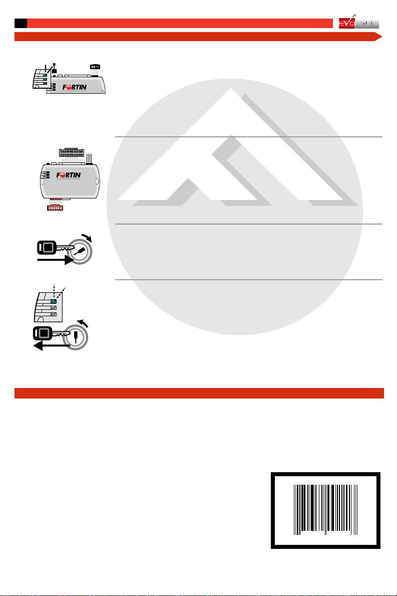
Press the programming switch while
inserting the 4 Pins connector (Data-Link)
into the EVO-ALL module.
Hold the programming button and when
the blue LED is ON release the button.
The Blue LED will illuminate to indicate
you are in programming mode.
Turn the key to the "ON" position.
Once the LED Blue starts to flash rapidly
turn the key to the OFF position.
The Blue LED will turn off to indicate
the module has been programmed.
Tournez la clef en position ignition.
Lorsque la DEL bleu clignote rapidement,
tournez la clef en position OFF.
La DEL bleu s'éteint pour indiquer que
le module est programmé.
Pressez le bouton de programmation
en insérant le connecteur 4 pins
dans le EVO-ALL.
Maintenez le bouton de programmation
enfoncé et lorsque la DEL Bleu
s'allume relâchez le bouton.
La DEL bleu indique le début de la
programmation.
(Data-
Link)
1
START
IGN
OFF
START
IGN
OFF
1
2
3
EVO-ALL
2
3
4
DATA-LINK
PROGRAMMING PROCEDURE ! PROCÉDURE DE PROGRAMMATION
Insérez le connecteur 20 pins.
Insert the 20 pin connector.
Insert the6 pin red connector.
Insérez le connecteur 6 pins.
Insérez l'autre connecteur si requis.
Insert the other connector if required.
4 PIN
CO
NN.
2
0
PIN
CO
NN.
6
PIN RED
CO
NN.
7370350 00221
WARNING / TECH SUPPORT / MISE EN GARDE / SUPPORT TECHNIQUE
L'information de ce guide est fournie sur la base de représentation (telle quelle) sans
aucune garantie de précision et d'exactitude. Il est de la seule responsabilité de
l'installateur de vérifier tous les fils et circuit avant défectuer les connections. Seule une
sonde logique ou un multimètre digital doivent être utilisés. FORTIN Electronic systems
n'assume aucune responsabilité de l'exactitude de l'information fournie. L'installation
(dans chaque cas) est la responsabilité de l'installateur effectuant le travail. FORTIN
Electronic system n'assume aucune responsabilité suite à l'installation, que celle-ci soit
bonne ou mauvaise ou de n'importe autre type. Ni le manufacturier, ni le distributeur ne
se considèrent responsables des dommages causés ou ayant pu être causés,
indirectementoudirectement,parcemodule,exceptéleremplacementdecemoduleen
casdedéfectuositédefabrication. Ce module doit êtreinstalléparuntechnicienqualifié.
L'information fournie dans ce guide est une suggestion. Ce guide d'instruction peut faire
l’objet de changement sans préavis. Consultez le www.ifar.ca pour voir la plus récente
version.
Theinformationon this sheet is providedonan(asis) basis with no representation orwarrantyofaccuracywhatsoever.Itisthesole
responsibility of the installer to check and verify any circuit before connecting to it. Only a computer safe logic probe or digital
multimetershouldbe used. FORTINElectronicsystem assumes absolutely no liabilityorresponsibilitywhatsoeverpertainingto the
accuracyorcurrencyoftheinformationsupplied.Theinstallationineverycaseisthesoleresponsibilityoftheinstallerperformingthe
workandFORTINElectronicsystem assumesnoliabilityorresponsibility whatsoeverresultingfromanytype ofinstallation,whether
performedproperly,improperly orany other way.Neitherthemanufacturer or distributor of this module isresponsible of damages of
anykindindirectlyordirectlycausedbythismodule,exceptforthereplacementofthismodule incaseofmanufacturingdefects.This
modulemust beinstalledby qualifiedtechnician.Theinformationsuppliedis aguideonly.Thisinstructionguide maychangewithout
notice.Visitwww.ifar.catogetlatestversion.
Copyright © 2009-2010,
FORTIN AUTO RADIO INC
ALL RIGHTS RESERVED
PATENTE PENDING
4This manual may change without notice. www.ifar.ca for latest version.

Other manuals for EVO-ALL

21

Other Fortin Automobile Accessories manuals

Fortin KEY-OVERRIDE-ALL User manual

Fortin

Fortin KEY-OVERRIDE-ALL User manual

Fortin TB-SUBARU2 User manual

Fortin

Fortin TB-SUBARU2 User manual

Fortin EVO ALL Installation and operating instructions

Fortin

Fortin EVO ALL Installation and operating instructions

Fortin EVO ALL User manual

Fortin

Fortin EVO ALL User manual

Fortin EVO ONE THAR-ONE-HON6 User manual

Fortin

Fortin EVO ONE THAR-ONE-HON6 User manual

Fortin EVO-CAN User manual

Fortin

Fortin EVO-CAN User manual

Fortin EVO ONE User manual

Fortin

Fortin EVO ONE User manual

Fortin Evo One THAR-ONE-HON4 User manual

Fortin

Fortin Evo One THAR-ONE-HON4 User manual

Fortin PATS-GM User manual

Fortin

Fortin PATS-GM User manual

Fortin EVO ALL User manual

Fortin

Fortin EVO ALL User manual

Fortin EVO ALL User manual

Fortin

Fortin EVO ALL User manual

Fortin EVO-ALL-CHRT6 User manual

Fortin

Fortin EVO-ALL-CHRT6 User manual

Fortin EVO ALL User manual

Fortin

Fortin EVO ALL User manual

Fortin PASSLOCK-SL2 User manual

Fortin

Fortin PASSLOCK-SL2 User manual

Fortin EVO ALL User manual

Fortin

Fortin EVO ALL User manual

Fortin EVO ONE User manual

Fortin

Fortin EVO ONE User manual

Fortin EVO ALL THAR-FOR4 User manual

Fortin

Fortin EVO ALL THAR-FOR4 User manual

Fortin EVO-GMT1 User manual

Fortin

Fortin EVO-GMT1 User manual

Fortin THAR-CHR3 User manual

Fortin

Fortin THAR-CHR3 User manual

Fortin EVO-ALL User manual

Fortin

Fortin EVO-ALL User manual

Fortin PATS-GM2 User manual

Fortin

Fortin PATS-GM2 User manual

Fortin EVO ONE Installation and operating instructions

Fortin

Fortin EVO ONE Installation and operating instructions

Fortin EVO ONE User manual

Fortin

Fortin EVO ONE User manual

Fortin TB-TOYOTA User manual

Fortin

Fortin TB-TOYOTA User manual

Popular Automobile Accessories manuals by other brands

Whispbar K406W Fitting instructions

Whispbar

Whispbar K406W Fitting instructions

Livoo TEA228 user manual

Livoo

Livoo TEA228 user manual

Thule Transporter Combi 665C manual

Thule

Thule Transporter Combi 665C manual

Rostra REARSIGHT OnStar 250-8822 installation instructions

Rostra

Rostra REARSIGHT OnStar 250-8822 installation instructions

Aegis Air Spoiler quick start guide

Aegis

Aegis Air Spoiler quick start guide

HUSKY LINERS 2995 Care and use instructions

HUSKY LINERS

HUSKY LINERS 2995 Care and use instructions

Axxess AX-AM-MB92 installation instructions

Axxess

Axxess AX-AM-MB92 installation instructions

ZAERO DESIGN EVO-1 installation manual

ZAERO DESIGN

ZAERO DESIGN EVO-1 installation manual

Shell NewMotion Home Advanced 2.1 Quick installation guide

Shell

Shell NewMotion Home Advanced 2.1 Quick installation guide

dirna Bergstrom Bycool Green Line Compact 3.0 Mounting instructions

dirna Bergstrom

dirna Bergstrom Bycool Green Line Compact 3.0 Mounting instructions

Brodit ProClip 854702 manual

Brodit

Brodit ProClip 854702 manual

MayPole BC2080 quick start guide

MayPole

MayPole BC2080 quick start guide

Facom DL.2A2L Original instructions

Facom

Facom DL.2A2L Original instructions

Phonocar 4/503 installation instructions

Phonocar

Phonocar 4/503 installation instructions

Scosche StuckUP IHW10 quick start guide

Scosche

Scosche StuckUP IHW10 quick start guide

Gembird TA-CH-003 user manual

Gembird

Gembird TA-CH-003 user manual

TOP VEHICLE TECH KWBMW1 installation manual

TOP VEHICLE TECH

TOP VEHICLE TECH KWBMW1 installation manual

Whispbar K668 manual

Whispbar

Whispbar K668 manual

manuals.online logo
manuals.online logoBrands
  • About & Mission
  • Contact us
  • Privacy Policy
  • Terms and Conditions

Copyright 2025 Manuals.Online. All Rights Reserved.