manuals.online logo
Brands
  1. Home
  2. •
  3. Brands
  4. •
  5. Monacor
  6. •
  7. Automobile Accessories
  8. •
  9. Monacor Carpower CAP-10T User manual

Monacor Carpower CAP-10T User manual

Power-Kondensator
Bitte lesen Sie diese Anleitung vor der Installation gründlich
durch und heben Sie sie für ein späteres Nachlesen auf.
1 Verwendungsmöglichkeiten
Dieser Power-Kondensator dient in Kraftfahrzeugen zur
Stabilisierung der 12-V-Versorgungsspannung für Audio-
Endstufen. Er gleicht die Belastung bei besonders kräfti-
gen Bässen aus, wodurch eine höhere Verstärkerleistung
und eine deutliche Klangverbesserung erreicht wird.
2 Sicherheitshinweise
Der Kondensator entspricht allen erforderlichen Richtlinien
der EU und ist deshalb mit gekennzeichnet.
GSchützen Sie den Kondensator vor Feuchtigkeit und ex-
tremen Temperaturen (zulässiger Einsatztemperaturbe-
reich
-
20 °C bis +60 °C).
GFür die Reinigung nur ein weiches, trockenes Tuch ver-
wenden, niemals Wasser oder Chemikalien.
GWird der Kondensator zweckentfremdet, nicht sicher
montiert, falsch angeschlossen oder nicht fachgerecht
repariert, kann keine Haftung für daraus resultierende
WARNUNG Der Anschluss des Kondensators an das
12-V-Bordnetz darf nur durch qualifiziertes
Fachpersonal erfolgen. Dabei ist beson-
dere Sorgfalt geboten. Bei Kurzschlüssen
können gefährlich hohe Ströme fließen.
Der Kondensator muss fest und fachgerecht an einer
mechanisch stabilen Stelle im Fahrzeug montiert wer-
den, damit er sich nicht löst und zu einem gefährlichen
Geschoss wird.
Sach- oder Personenschäden und keine Garantie für
den Kondensator übernommen werden.
3 Installation
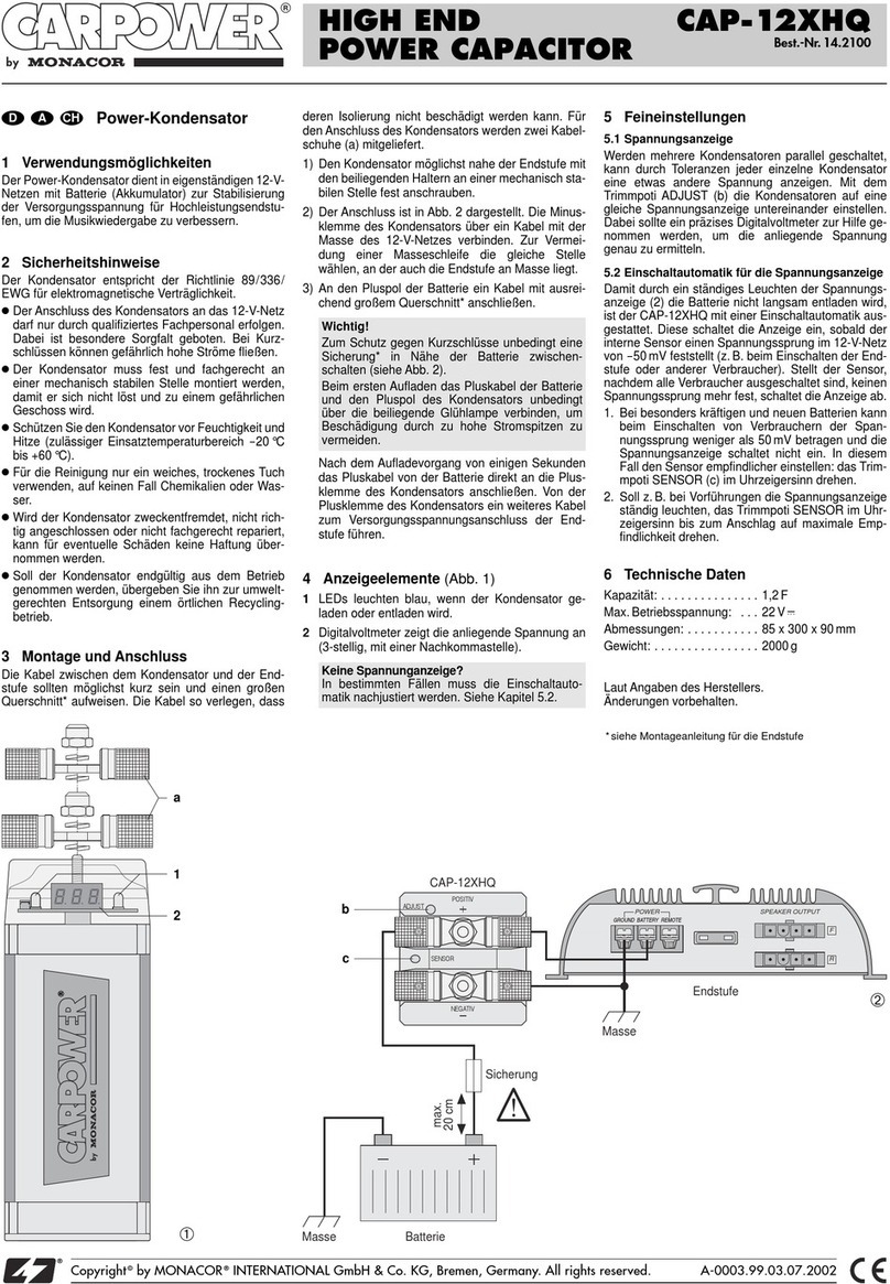
Die Kabel zwischen dem Kondensator und der Endstufe
sollten möglichst kurz sein und einen großen Querschnitt*
aufweisen. Die Kabel so verlegen, dass deren Isolierung
nicht beschädigt werden kann.
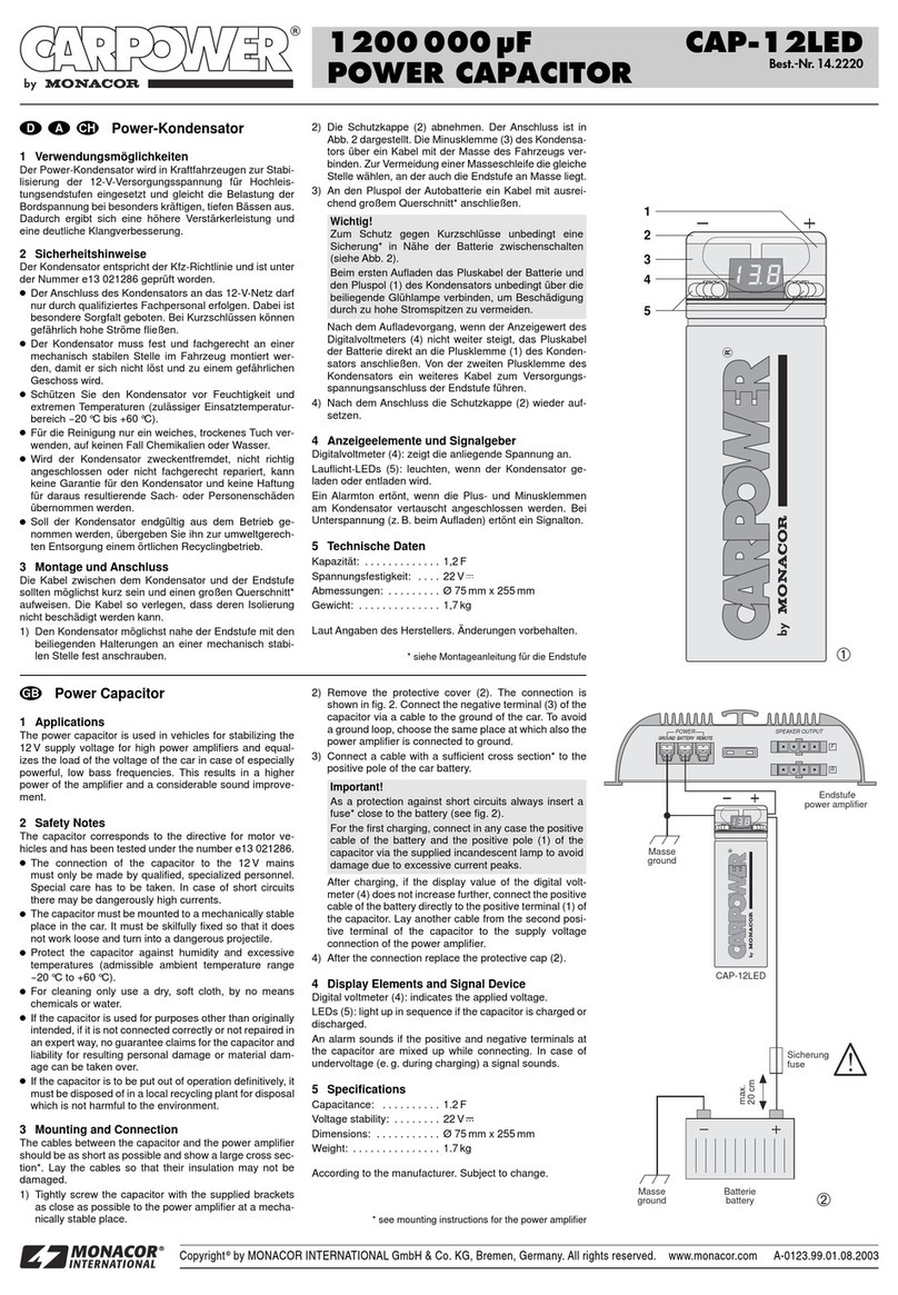
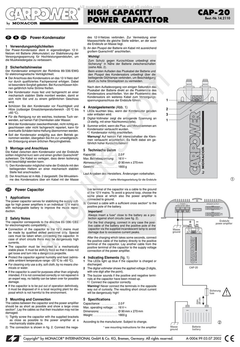
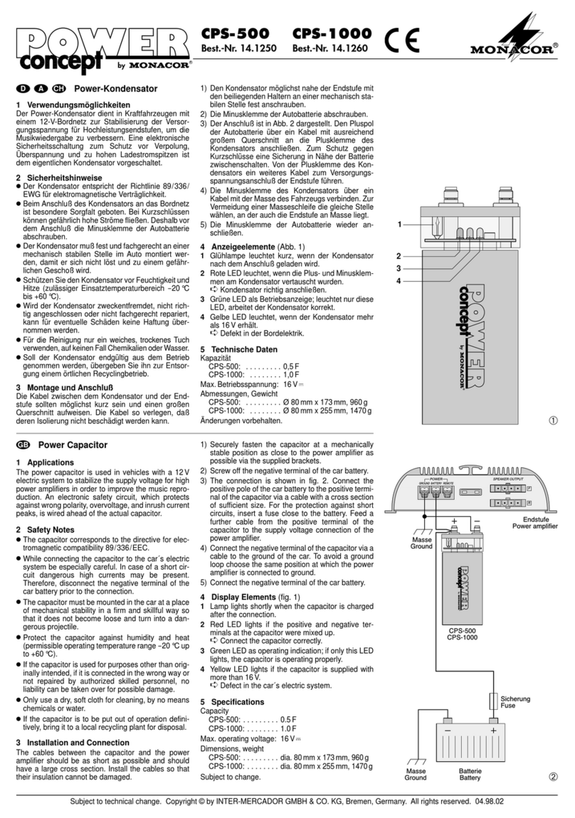
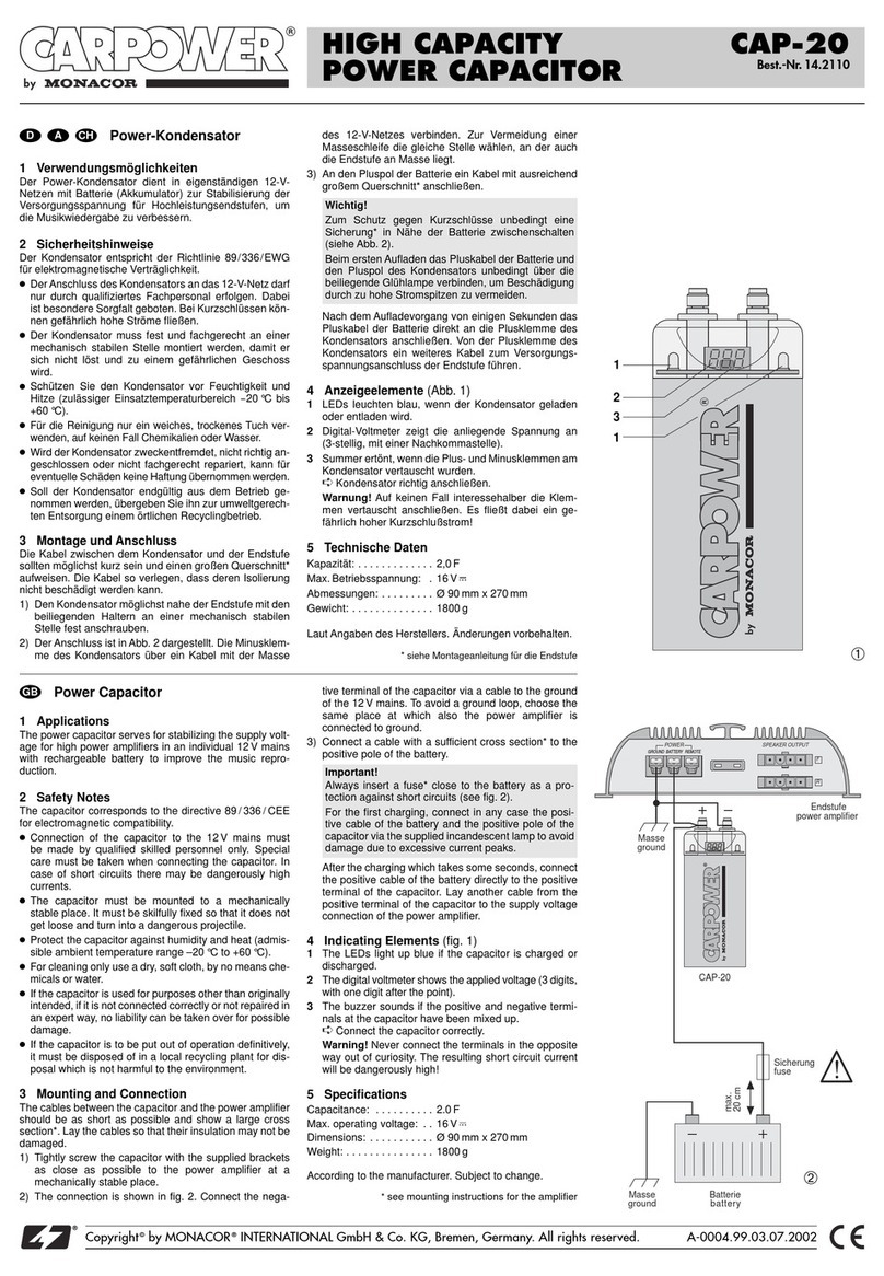
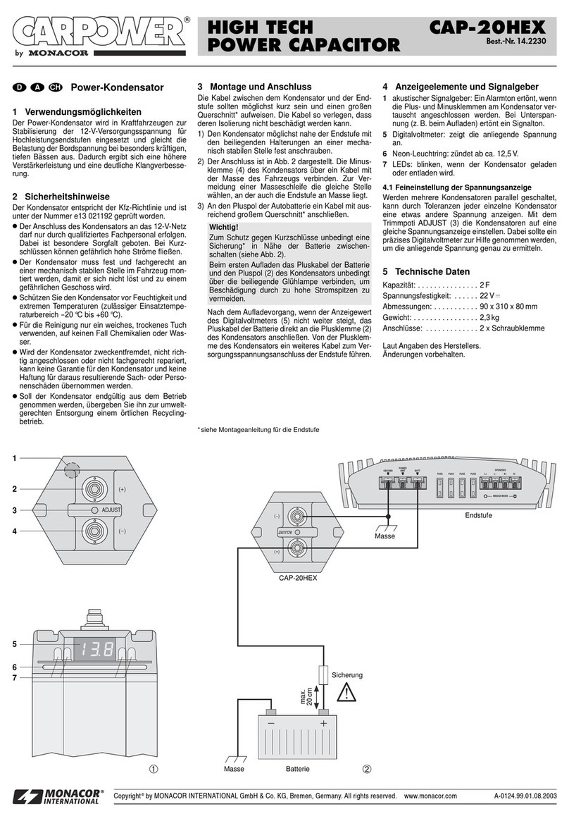
1) Den Kondensator möglichst nahe der Endstufe mit den
beiliegenden Halterungen (5) fest anschrauben.
2) Einen der beiden Minusanschlüsse (2) des Kondensa-
tors über ein Kabel mit der Masse des Fahrzeugs ver-
binden. Zur Vermeidung einer Masseschleife die gleiche
Stelle wählen, an der auch die Endstufe an Masse liegt.
3) An den Pluspol der Autobatterie ein Kabel mit ausrei-
chend großem Querschnitt* anschließen.
Zum Schutz bei einem Kurzschluss unbedingt eine
Sicherung* in Nähe der Batterie zwischenschalten
(siehe Abb. unten).
Zum ersten Aufladen des Kondensators das Pluskabel
von der Batterie unbedingt über eine 12-V-Glühlampe
mit einem der Plusanschlüsse (1) verbinden. Dadurch
wird der Ladestrom begrenzt und eine Beschädigung
durch zu hohe Stromspitzen verhindert.
Vorsicht! Bei Verwechselung des Plus- und Minus-
pols am Kondensator ertönt ein Signalton. Sofort das
Pluskabel vom Kondensator entfernen!
Soll der Kondensator endgültig aus dem Betrieb
genommen werden, übergeben Sie ihn zur um-
weltgerechten Entsorgung einem örtlichen Re-
cyclingbetrieb.
4) Nach dem Aufladevorgang, wenn der Anzeigewert des
Displays (4) nicht weiter steigt, die Lampe entfernen und
das Pluskabel der Batterie direkt an die Plusklemme des
Kondensators anschließen. Von einem anderen Plusan-
schluss des Kondensators ein weiteres Kabel zum End-
stufenanschluss für die Betriebsspannung führen.
4 Spannungs- und Betriebsanzeige
Die blauen Betriebsanzeige-LEDs (3) und die digitale
Spannungsanzeige (4) leuchten ab einer Ladespannung
von ca. 5,5 V.
blinkt: . Spannung < 9,2 V = Unterspannung
…
blinkt: . . . . Unterspannung, jedoch wird der Wert anzeigt
… : gemessene Ladespannung
blinkt: . Spannung > 15,9 V = Überspannung
Ändert sich die Spannung nicht, schalten sich die Span-
nungs- und die Betriebsanzeige nach ca. 2 Minuten aus,
um z. B. bei ausgeschaltetem Motor die Autobatterie nur
mit einem geringen Strom zu belasten. Bei einer Span-
nungsänderung schalten sich die Anzeigen wieder ein.
5 Technische Daten
Kapazität: . . . . . . . . . . . . . . . . 1 F ± 10 %
Betriebsspannung: . . . . . . . . . 12 V
Spannungsfestigkeit: . . . . . . . . 20 V
Maße ohne Halterung: . . . . . . ∅75 mm × 245 mm
Gewicht: . . . . . . . . . . . . . . . . . 1,5 kg
Änderungen vorbehalten.
than originally intended, if it is not safely installed or cor-
rectly connected, or if it is not repaired in an expert way.
3 Installation
The cable between the capacitor and the power amplifier
should be as short as possible and have a large cross sec-
tion*. Lay the cables in such a way that their insulation will
not be damaged.
1) Tightly screw on the capacitor with the supplied brack-
ets (5), as close as possible to the power amplifier.
2) Connect one of the two negative terminals (2) of the
capacitor via a cable to the ground of the car. To prevent
a ground loop, use the same place where the power
amplifier is connected to ground.
3) Connect a cable with a sufficient cross section* to the
positive pole of the car battery.
As a protection against short circuits, always insert a
fuse* close to the battery (see figure below).
When charging the capacitor for the first time, it is
essential to connect the positive cable of the battery
via a 12 V incandescent lamp to one of the positive ter-
minals (1). This will limit the charging current and pre-
vent damage due to excessive current peaks.
Caution! If the positive and negative poles on the
capacitor are confused, a signal will sound. In this
case, disconnect the positive cable from the capacitor
immediately!
If the capacitor is to be put out of operation defini-
tively, take it to a local recycling plant for a dispos-
al which will not be harmful to the environment.
4)
After the charging process, if the value indicated on the
display (4) does not rise any more, remove the lamp and
connect the positive cable of the battery directly to the
positive terminal of the capacitor. Lay a further cable
from another positive terminal of the capacitor to the
connection for operating voltage of the power amplifier.
4 Voltage and Power Indications
The blue power LEDs (3) and the digital voltage indication
(4) will light up from a charging voltage of approx. 5.5 V.
flashing: voltage < 9.2 V = undervoltage
…
flashing: undervoltage, but the value will be indicated
… : charging voltage measured
flashing: voltage > 15.9 V = overvoltage
If the voltage does not change, the voltage and power indi-
cations will be deactivated after approx. 2 minutes, e. g. for
drawing only a low current from the car battery when the
engine is switched off. If the voltage changes, the indica-
tions will be activated again.
5 Specifications
Capacitance: . . . . . . . . . . . . . . 1 F ± 10 %
Operating voltage: . . . . . . . . . . 12 V
Voltage stability: . . . . . . . . . . . 20 V
Dimensions without bracket: . . ∅75 mm × 245 mm
Weight: . . . . . . . . . . . . . . . . . . 1.5 kg
Subject to technical modification.
Copyright©by MONACOR INTERNATIONAL GmbH & Co. KG, Bremen, Germany. All rights reserved. www.carpower.com A-1002.99.01.05.2009
®
1000 000 µF
POWER CAPACITOR
CAP-10T
Best.-Nr. 14.2750
D A CH
GB
!
1
2
3
4
Endstufe
power amplifier
Sicherung
fuse
max.
20 cm
Batterie
battery Masse
ground
*siehe Montageanleitung der Endstufe
5
Power Capacitor
Please read these operating instructions carefully prior to
installation and keep them for later reference.
1 Applications
This power capacitor is used in motor vehicles for stabiliz-
ing the 12 V supply voltage for audio power amplifiers. It
will equalize the load in case of extra powerful bass fre-
quencies resulting in higher amplifier power and consider-
able sound improvement.
2 Safety Notes
The capacitor corresponds to all required directives of the
EU and is therefore marked with .
GProtect the capacitor against humidity and extreme tem-
peratures (admissible ambient temperature range
-
20 °C
to +60 °C).
GFor cleaning only use a dry, soft cloth; never use water
or chemicals.
GNo guarantee claims for the capacitor and no liability for
any resulting personal damage or material damage will
be accepted if the capacitor is used for other purposes
WARNING The capacitor must be connected to the
12 V electrical system of the car by skilled
personnel only. Take particular care: In
case of short circuits, there may be dan-
gerously high current.
Install the capacitor safely and expertly at a mechanically
stable place in the car to ensure that it will not work loose
and become a dangerous projectile.
*see mounting instruction of power amplifier
Condensateur de puissance
Veuillez lire la présente notice avec attention avant lʼins-
tallation et conservez-la pour pouvoir vous y reporter ulté-
rieurement.
1 Possibilités dʼutilisation
Ce condensateur de puissance est utilisé dans des véhi-
cules pour stabiliser la tension dʼalimentation 12 V pour
des amplificateurs finaux audio et compense la charge
dans le cas de fréquences graves particulièrement puis-
santes. On obtient ainsi une puissance dʼamplificateur
plus importante et une amélioration distincte du son.
2 Conseils dʼutilisation et de sécurité
Le condensateur répond à toutes les directives néces-
saires de lʼUnion européenne et porte donc le symbole .
GProtégez le condensateur de lʼhumidité et de tempéra-
tures extrêmes (plage de température de fonctionne-
ment autorisée :
-
20 °C à +60 °C).
GPour le nettoyer, utilisez uniquement un chiffon sec et
doux, en aucun cas de produits chimiques ou dʼeau.
G
Nous déclinons toute responsabilité en cas de dommages
matériels ou corporels si le condensateur est utilisé dans
AVERTISSEMENT Le branchement du condensateur à
lʼalimentation 12 V du véhicule ne
doit être effectué que par un techni-
cien habilité. Il convient dʼêtre parti-
culièrement prudent. En cas de
courts-circuits, des courants élevés
peuvent circuler et être dangereux.
Le condensateur doit être monté de manière fixe et
appropriée, dans un endroit mécaniquement stable dans
le véhicule pour éviter quʼil ne se désolidarise de son
support et ne se transforme en projectile dangereux.
un but autre que celui pour lequel il a été conçu, sʼil nʼest
pas installé de manière sûre, sʼil nʼest pas correctement
branché ou sʼil nʼest pas réparé par une personne habili-
tée ; en outre, la garantie deviendrait caduque.
3 Installation
Les cordons entre le condensateur et lʼamplificateur
devraient être le plus court possible et dʼune grande sec-
tion*. Placez les câbles de telle sorte que leur isolation ne
puisse en aucun cas être endommagée.
1) Vissez fermement le condensateur aussi proche que
possible de lʼamplificateur avec les supports livrés (5).
2) Connectez une des deux bornes moins (2) du conden-
sateur via un câble, à la masse du véhicule. Pour éviter
tout bouclage de masse, choisissez le même endroit
que celui où se trouve la masse de lʼamplificateur.
3) Reliez un câble avec une section suffisamment grande*
au pôle plus de la batterie du véhicule.
Pour la protection contre un court-circuit], un fusible*
doit impérativement être intercalé à proximité de la
batterie (voir schéma ci-dessous).
Lors de la première charge du condensateur, reliez
impérativement le câble plus de la batterie à une des
bornes plus (1) via une lampe à incandescence 12 V
fournie : vous éviterez ainsi tout dommage causé par
des pointes de courant trop importantes.
Attention ! Si les pôles plus et moins du conden-
sateur sont inversés sur le condensateur, un signal
Lorsque le condensateur est définitivement retiré
du service, vous devez le déposer dans une
usine de recyclage de proximité pour contribuer à
son élimination non polluante.
4) Après le processus de charge, lorsque la valeur de lʼaf-
fichage (4) nʼaugmente plus, retirez la lampe et reliez le
câble plus de la batterie directement à la borne plus du
condensateur. Tirez un second câble dʼune des bornes
plus du condensateur vers la borne de la tension dʼali-
mentation de lʼamplificateur.
4 Indicateurs de tension et de fonctionnement
Les LEDs (3) bleues et lʼaffichage digital de tension (4)
brillent à partir dʼune tension de charge de 5,5 V environ.
clignote : tension < 9,2 V = sous-tension
…
clignote : . . . sous-tension mais la valeur est affichée
… : tension de charge mesurée
clignote : tension > 15,9 V = surtension
Si la tension ne se modifie pas, les indicateurs de tension
et de fonctionnement sʼéteignent après 2 minutes environ
pour par exemple nʼutiliser quʼun faible courant de la bat-
terie du véhicule lorsque le moteur est éteint. En cas de
modification de la tension, les affichages se rallument.
5 Caractéristiques techniques
Capacité : . . . . . . . . . . . . . . . . 1 F ± 10 %
Tension fonctionnement : . . . . 12 V
Tenue en tension : . . . . . . . . . . 20 V
Dimensions sans support : . . . ∅75 mm × 245 mm
Poids : . . . . . . . . . . . . . . . . . . . 1,5 kg
Tout droit de modification réservé.
sonore retentit. Débranchez immédiatement le câble
plus du condensateur !
Condensatore di potenza
Vi preghiamo di leggere attentamente le presenti istruzioni
prima dellʼinstallazione e di conservarle per un uso futuro.
1 Possibilità dʼimpiego
Questo condensatore di potenza serve negli autoveicoli per
stabilizzare la tensione dʼalimentazione di 12 V dei finali
audio. Riesce a compensare il carico in caso di bassi parti-
colarmente potenti, procurando in tal modo una maggiore
potenza dellʼamplificatore e un suono decisamente migliore.
2 Avvertenze di sicurezza
Il condensatore è conforme a tutte le direttive richieste del-
lʼUE e pertanto porta la sigla .
GProteggere il condensatore dallʼumidità e da temperature
estreme (temperatura ammessa fra
-
20 °C e +60 °C).
GPer la pulizia usare solo un panno morbido, asciutto;
non impiegare in nessun caso prodotti chimici o acqua.
GNel caso dʼuso improprio, di montaggio non sicuro, di col-
legamento sbagliato o di riparazione non a regola dʼarte
del condensatore, non si assume nessuna responsabilità
AVVERTIMENTO Il collegamento del condensatore con
la rete 12 V di bordo deve essere
fatto solo da personale qualificato.
Occorre procedere con particolare
cautela. In caso di cortocircuito ci
possono essere delle alte correnti
pericolose.
Il condensatore deve essere montato nei veicoli a regola
dʼarte e in un punto meccanicamente stabile per esclu-
dere che si stacchi diventando un proiettile pericoloso.
per eventuali danni consequenziali a persone o a cose e
non si assume nessuna garanzia per il condensatore.
3 Installazione
I cavi fra il condensatore e il finale dovrebbero essere pos-
sibilmente corti e presentare una grande sezione*. Instal-
lare i cavi in modo tale che il loro isolamento non possa
essere danneggiato.
1) Avvitare bene il condensatore il più vicino possibile al
finale servendosi dei supporti (5) in dotazione.
2) Con un cavo, collegare uno dei due contatti negativi (2)
del condensatore con la massa del veicolo. Per esclu-
dere degli anelli di terra scegliere lo stesso punto dove
anche il finale è collegato con la massa.
3) Collegare un cavo con sezione sufficiente* con il polo
positivo della batteria dellʼauto.
Come protezione in caso di cortocircuito inserire assolu-
tamente un fusibile* vicino alla batteria (vedi fig. in calce).
Per la prima carica del condensatore collegare asso-
lutamente il cavo positivo proveniente dalla batteria
con uno dei contatti positivi (1) inserendo una lampa-
dina di 12 V. In questo modo, la corrente di carica
viene limitata e si evita il danneggiamento per via dei
picchi di corrente troppo alti.
Attenzione! Se si scambiano i poli positivi e negativi
sul condensatore, viene emesso un segnale acustico.
Staccare subito il cavo positivo dal condensatore!
Se si desidera eliminare il condensatore definiti-
vamente, consegnarlo per lo smaltimento ad
unʼistituzione locale per il riciclaggio.
4) Dopo la carica, quando il valore indicato sul display (4)
non aumenta più, togliere la lampadina e collegare il
cavo positivo della batteria direttamente con il morsetto
positivo del condensatore. Da un altro contatto positivo
del condensatore portare un altro cavo verso il contatto
del finale per assicurare la tensione dʼesercizio.
4 Indicazioni della tensione e di funzionamento
I LED blu di funzionamento (3) e lʼindicazione digitale della
tensione (4) si accendono da una tensione di carica di
5,5 V circa.
lampeggia: Tensione < 9,2 V = tensione troppo bassa
…
lampeggia: . . . Tensione troppo bassa, ma il valore viene
indicato
… : . . Tensione di carica misurata
lampeggia: Tensione > 15,9 V = sovratensione
Se la tensione non cambia, lʼindicazione della tensione e
di funzionamento si spegne dopo 2 minuti circa per pesare
sulla batteria dellʼauto solo con una corrente ridotta, p. es.
in caso di motore spento. Se la tensione cambia, le spie si
riaccendono.
5 Dati tecnici
Capacità : . . . . . . . . . . . . . . . . 1 F ± 10 %
Tensione dʼesercizio: . . . . . . . . 12 V
Rigidità dielettrica: . . . . . . . . . . 20 V
Dimensioni senza supporto: . . ∅75 mm × 245 mm
Peso: . . . . . . . . . . . . . . . . . . . . 1,5 kg
Con riserva di modifiche tecniche.
Copyright©by MONACOR INTERNATIONAL GmbH & Co. KG, Bremen, Germany. All rights reserved. www.carpower.com A-1002.99.01.05.2009
®
1000 000 µF
POWER CAPACITOR
CAP-10T
Best.-Nr. 14.2750
I
F B CH
*vedi le istruzioni di montaggio del finale
!
1
2
3
4
Amplificateur final
Finale
Fusible
Fusibile
max.
20 cm
Batterie
Batteria Masse
Massa
5
*voir notice de montage de lʼamplificateur
Condensador de potencia
Lea atentamente estas instrucciones de funcionamiento
antes de la instalación y guárdelas para posteriores usos.
1 Aplicaciones
Este condensador se utiliza en vehículos a motor para
estabilizar la alimentación de 12 V para amplificadores de
audio. Iguala la carga en caso de exceso de graves para
crear una mayor potencia de amplificación y una mejora
considerable del sonido.
2 Notas de Seguridad
El condensador cumple con todas las directivas requeridas
por la UE y por lo tanto está marcado con el símbolo .
GProteja el condensador de la humedad y de temperatu-
ras extremas (temperatura ambiente admisible:
-
20 °C
a +60 ºC).
GUtilice sólo un paño suave y seco para la limpieza; no
utilice nunca ni agua ni productos químicos.
GNo podrá reclamarse garantía o responsabilidad alguna
por cualquier daño personal o material resultante si el
condensador se utiliza para otros fines diferentes a los
originalmente concebidos, si no se instala o se conecta
ADVERTENCIA El condensador tiene que conectarse
al sistema eléctrico de 12 V del coche
sólo mediante personal cualificado.
Preste especial atención: En caso de
cortocircuito, puede haber corrientes
peligrosas.
Instale el condensador de un modo seguro mediante
expertos en un lugar del coche que sea mecánicamente
estable para asegurarse de que no se suelta.
correctamente, no se utiliza adecuadamente o no se
repara por expertos.
3 Instalación
El cableado entre el condensador y el amplificador tendría
que ser lo más corto posible y tener un gran corte de sección*.
Coloque el cableado de modo que su aislamiento no se dañe.
1) Atornille fuertemente el condensador con los soportes
de montaje entregados (5), tan cerca como sea posible
del amplificador.
2) Conecte uno de los dos terminales negativos (2) del
condensador mediante un cable a la masa del coche.
Para prevenir bucles de masa, utilice el mismo en el
que el amplificador se ha conectado a la masa.
3) Conecte un cable con un corte de sección suficiente* al
polo positivo de la batería del coche.
Como protección contra cortocircuitos, inserte siempre
un fusible* cerca de la batería (ver fig. a continuación).
Cuando cargue el condensador por primera vez, es
esencial que conecte el cable positivo de la batería
mediante una lámpara incandescente de 12 V a uno
de los terminales positivos (1). Esto limitará la
corriente de carga y prevendrá daños debido a picos
de corriente excesivos.
¡Advertencia! Si se han confundido el polo positivo y el
negativo, sonará una señal. En este caso, desconecte
el cable positivo del condensador inmediatamente.
Si va a poner el condensador fuera de servicio
definitivamente, llévelo a la planta de reciclaje
más cercana para que su eliminación no sea per-
judicial para el medioambiente.
4) Después del proceso de carga, si el valor indicado en
el visualizador (4) no sube más, quite la lámpara y
conecte el cable positivo de la batería directamente al
terminal positivo del condensador. Ponga otro cable
desde otro terminal positivo del condensador a la cone-
xión para el voltaje de funcionamiento del amplificador.
4 Indicaciones de Voltaje y Potencia
Los LEDs Power azules (3) y la indicación digital de vol-
taje (4) se iluminan a partir de una carga de 5,5 V aprox.
parpadeando: Voltaje < 9,2 V = bajo voltaje
…
parpadeando: . . . Bajo voltaje, pero se indica el valor
… : . . . . . Voltaje de carga medido
parpadeando: Voltaje > 15,9 V = sobrevoltaje
Si el voltaje no cambia, tanto el voltaje como las indica-
ciones de potencia se desactivan después de unos 2 mi-
nutos, p. ej. para enviar sólo una corriente débil desde la
batería del coche cuando el motor está apagado. Si el vol-
taje cambia, se activan las indicaciones de nuevo.
5 Especificaciones
Capacitancia: . . . . . . . . . . . . . 1 F ± 10 %
Voltaje de funcionamiento: . . . 12 V
Estabilidad de voltaje: . . . . . . 20 V
Dimensiones sin soporte: . . . . ∅75 mm × 245 mm
Peso: . . . . . . . . . . . . . . . . . . . . 1,5 kg
Sujeto a modificaciones técnicas.
Kondensator mocy 1 000 000 μF
Przed przystąpieniem do pracy proszę dokładnie zapo-
znać się z niniejszą instrukcją i zachować ją do wglądu.
1 Zastosowanie
Kondensator mocy jest używany w samochodowych sys-
temach nagłośnienia w celu stabilizacji napięcia zasilania
12 V dla wzmacniaczy mocy. Poprawia to ich działanie,
szczególnie w zakresie niskich częstotliwości w momen-
cie, gdy wymagana jest znaczna ilość pobieranej energii z
akumulatora. Rezultatem jest zwiększenie mocy wzmac-
niacza oraz poprawa jakości dźwięku.
2 Środki bezpieczeństwa
Kondensator mocy spełnia wszystkie wymagania norm
UE, dlatego został oznaczony symbolem .
GKondensator należy chronić przed działaniem wody,
wysokiej wilgotności oraz wysokiej temperatury (do-
puszczalny zakres wynosi
-
20 °C do +60 °C).
GDo czyszczenia używać suchej miękkiej ściereczki. Nie
stosować wody i środków chemicznych.
GProducent ani dostawca nie ponoszą odpowiedzialno-
ści za uszkodzenie sprzętu bądź obrażenia użytkow-
nika, jeżeli urządzenie było używane niezgodnie z prze-
UWAGA
Podłączenie kondensatora mocy do 12 V sys-
temu elektrycznego w samochodzie na-leży
zlecić specjaliście. Należy zachować szcze-
gólną ostrożność: w przypadku zwarcia poja-
wia się prąd o bardzo wysokim natężeniu.
Kondensator należy zainstalować w samochodzie w
sposób stabilny, aby nie uległ uszkodzeniu mechanicz-
nemu uszkodzeniu i nie stanowił zagrożenia dla pasaże-
rów na wypadek poluzowania.
znaczeniem, zostało nieodpowiednio podłączone lub
poddane nieautoryzowanej naprawie.
3 Instalacja
Kable połączeniowe pomiędzy kondensatorem a wzmac-
niaczem mocy powinny być jak najkrótsze i o jak najwięk-
szym przekroju poprzecznym*. Należy je tak ułożyć, aby
uniemożliwić ich uszkodzenie.
1) Przykręcić mocno i pewnie kondensator, wykorzystując
uchwyty montażowe (5), możliwie najbliżej wzmacnia-
cza mocy.
2) Podłączyć jeden z dwóch ujemnych terminali (2) kon-
densatora do masy samochodu. Aby uniknąć powsta-
nia pętli masy należy wykorzystać to samo miejsce jak
w przypadku wzmacniacza mocy.
3) Podłączyć zacisk dodatni kondensatora do akumula-
tora, za pomocą przewodu o odpowiednim przekroju*.
Jako zabezpieczenie przeciwzwarciowe, zawsze
należy włączać w obwód połączeniowy bezpiecznik,
maksymalnie blisko akumulatora (patrz rys. poniżej).
Przy pierwszym ładowaniu kondensatora, aby unik-
nąć jego uszkodzenia w wyniku działania nadmier-
nego prądu rozruchowego, należy w obwód połącze-
niowy przed dodatnim terminalem (1) włączyć
ogranicznik np. odpowiednią żarówkę.
Uwaga! W przypadku zamiany biegunów, pojawi się
ostrzegający sygnał dźwiękowy, należy wówczas natych-
miast odłączyć dodatni przewód od kondensatora!
Po całkowitym zakończeniu eksploatacji, należy
oddać urządzenie do punktu recyklingu, aby nie
zaśmiecać środowiska.
4) Po naładowaniu, jeśli wartość podana na wyświetlaczu
(4) nie rośnie, odłączyć żarówkę i połączyć bezpośred-
nio zacisk dodatni akumulatora z zaciskiem dodatnim
kondensatora. Połączyć innym przewodem drugi za-
cisk dodatni kondensatora z zaciskiem zasilającym
wzmacniacza.
4 Wskazania napięcia i mocy
Niebieskie diody zasilania (3) oraz cyfrowy woltomierz (4)
zapalają się przy prądzie ładowania około 5,5 V.
miga: . . napięcie < 9,2 V = zbyt niskie
…
miga: . . . . . zbyt niskie napięcie, ale wartość jest poka-
zana
… : zmierzona wartość napięcia
miga: . . napięcie > 15,9 V = zbyt wysokie
Jeżeli napięcie się nie zmienia, wskazanie napięcia i mocy
zostanie wyłączone po około 2 minutach, aby zmniejszyć
pobór prądu przy wyłączonym silniku. Jeżeli wartość napię-
cia ulegnie zmianie wyświetlacz włączy się ponownie.
5 Specyfikacja
Pojemność: . . . . . . . . . . . . . . . 1 F ± 10 %
Zasilanie: . . . . . . . . . . . . . . . . . 12 V
Stabilność: . . . . . . . . . . . . . . . 20 V
Wymiary bez uchwytów: . . . . . ∅75 mm × 245 mm
Waga: . . . . . . . . . . . . . . . . . . . 1,5 kg
Z zastrzeżeniem możliwości zmian.
Copyright©by MONACOR INTERNATIONAL GmbH & Co. KG, Bremen, Germany. All rights reserved. www.carpower.com A-1002.99.01.05.2009
®
1000 000 µF
POWER CAPACITOR
CAP-10T
Best.-Nr. 14.2750
E
PL
!
1
2
3
4
Amplificador
wzmacniacz mocy
Fusible
bezpiecznik
max.
20 cm
Batería
akumulator Masa
masa
5
*Ver instrucciones de montaje del amplificador
*patrz instrukcja montażu wzmacniacza mocy

This manual suits for next models

1

Other Monacor Automobile Accessories manuals

Monacor CARPOWER 14.2110 User manual

Monacor

Monacor CARPOWER 14.2110 User manual

Monacor Carpower CAP-20 User manual

Monacor

Monacor Carpower CAP-20 User manual

Monacor Carpower HPB-450 User manual

Monacor

Monacor Carpower HPB-450 User manual

Monacor CARPOWER CAP-20HEX User manual

Monacor

Monacor CARPOWER CAP-20HEX User manual

Monacor Power Concept CPS-500 User manual

Monacor

Monacor Power Concept CPS-500 User manual

Monacor Carpower FGA-22HQ User manual

Monacor

Monacor Carpower FGA-22HQ User manual

Monacor Carpower ENF-30 User manual

Monacor

Monacor Carpower ENF-30 User manual

Monacor CARPOWER CAP-12LED User manual

Monacor

Monacor CARPOWER CAP-12LED User manual

Monacor CARPOWER CAP-12XHQ User manual

Monacor

Monacor CARPOWER CAP-12XHQ User manual

Popular Automobile Accessories manuals by other brands

Thule 2018 installation instructions

Thule

Thule 2018 installation instructions

Paser UNICOM SONY installation manual

Paser

Paser UNICOM SONY installation manual

Thule Kit 1033 instructions

Thule

Thule Kit 1033 instructions

Mid America Motorworks 623-870 instruction sheet

Mid America Motorworks

Mid America Motorworks 623-870 instruction sheet

Safe Fleet Rear View Safety RVS-699Q instruction manual

Safe Fleet

Safe Fleet Rear View Safety RVS-699Q instruction manual

TRUCKWRKS TT500000DS owner's manual

TRUCKWRKS

TRUCKWRKS TT500000DS owner's manual

Harbor Freight Tools 3343 Assembly and operating instructions

Harbor Freight Tools

Harbor Freight Tools 3343 Assembly and operating instructions

Gembird BTCC-03 user manual

Gembird

Gembird BTCC-03 user manual

POPULAR MECHANICS PMAC101 user guide

POPULAR MECHANICS

POPULAR MECHANICS PMAC101 user guide

Whispbar K334W Fitting Instructions for Basic Carrier

Whispbar

Whispbar K334W Fitting Instructions for Basic Carrier

BGS technic 9023 instruction manual

BGS technic

BGS technic 9023 instruction manual

Clarion PP-2538T Service manual

Clarion

Clarion PP-2538T Service manual

Cruz Evo Rack E26-158 Assembly instructions

Cruz

Cruz Evo Rack E26-158 Assembly instructions

Phonocar VM548 installation instructions

Phonocar

Phonocar VM548 installation instructions

Curt Manufacturing 70108 installation manual

Curt Manufacturing

Curt Manufacturing 70108 installation manual

EUFAB 11512 operating instructions

EUFAB

EUFAB 11512 operating instructions

Gamber Johnson TrimLine 7300-0600-03 user guide

Gamber Johnson

Gamber Johnson TrimLine 7300-0600-03 user guide

Yakima K853 instructions

Yakima

Yakima K853 instructions

manuals.online logo
manuals.online logoBrands
  • About & Mission
  • Contact us
  • Privacy Policy
  • Terms and Conditions

Copyright 2025 Manuals.Online. All Rights Reserved.