manuals.online logo
Brands
  1. Home
  2. •
  3. Brands
  4. •
  5. Soundoff Signal
  6. •
  7. Automobile Accessories
  8. •
  9. Soundoff Signal Mpower EMPSC07M Series User manual

Soundoff Signal Mpower EMPSC07M Series User manual

1.800.338.7337 / www.soundoffsignal.com
1
®
with Clear Duty® Technology
7x3 Silicone_STT 0321
!
WARNING
This product contains high intensity LED devices.
To prevent eye damage, DO NOT stare into the
light beam at close range.
STOP/TAIL & TURN LIGHTS
EMPSC07M(x)-(x) - 7X3 Quick Mount, Screw Mount, & Stud Mount
EMPSB0C9(x)-(x) - 6X4 Quick Mount, Screw Mount, & Stud Mount
•HIGH CURRENT interconnects must be properly terminated. Poor crimp quality can cause heat build-up and re. Follow crimp connector
manufacturer instructions.
•DO NOT install this product or route any wires in the Air Bag Deployment Zone. Refer to vehicle Owner’s Manual for deployment zones.
•Unit may become hot to touch during normal operation.
•Failure to properly install connectors, fuses or wiring may cause vehicle failure or re.
•Installation must only be performed by trained technician. Installer must determine vehicle wiring conguration and proper integration of system.
•Use proper wire gauge. All power wires connecting to positive (+) or negative (-) battery terminal or local chassis ground (-) must be sized to
supply at least 125% of max. current and properly fused at power source.
•Install protective grommets when routing wire through rewall or metal.
WARNING
NOTICE:
Installers and users must comply with all applicable federal, state and local laws regarding use and installation of warning devices.
Improper use or installation may void warranty coverage.
To review our Limited Warranty Statement & Return Policy for this or any SoundO Signal product, visit our website at www.soundosignal.com/tech-services/returns/.
If you have questions regarding this product, contact Technical Services, Monday - Friday, 8 a.m. to 5 p.m. ET at 1.800.338.7337 (press #4).
Questions or comments that do not require immediate attention may be emailed to techservices@soundosignal.com.
ENHANCING SAFETY THROUGH INNOVATION
MPOWER®
STOP/TAIL LIGHT
TECHNICAL SPECIFICATIONS
Input Voltage: 9-32Vdc
STOP/TAIL LIGHT
CURRENT CONSUMPTION (Amps)
12.8Vdc 25.6Vdc
Peak Peak
STOP 0.42 0.21
TAIL 0.04 0.02
TURN SIGNAL LIGHT
CURRENT CONSUMPTION (Amps)
12.8Vdc 25.6Vdc
Peak Average Peak Average
TURN 0.66 0.33 0.33 0.17
AFTER POWER IS ON, touching the WHITE wire to the
ground will allow you to change various settings on the
module. (refer to page 6).
NOTE: It is recommended to use the Stud Mount
option for any dynamic mount surfaces (i.e.
Swining Panels, Doors, and Tail Gates).
7X3 STOP/TAIL LIGHT
6X4 STOP/TAIL LIGHT
Protected by U.S. Patent 10,703,260 and Patents Pending
https://soundo󰀨signal.com/legal/patent-notication/
1.800.338.7337 / www.soundoffsignal.com
2
®
with Clear Duty® Technology
7x3 Silicone_STT 0321
1.800.338.7337 / www.soundoffsignal.com
2
7X3 QUICK MOUNT PART NUMBERS
EMPSC07M6-R - Stop/Tail & Turn Light, Quick Mount
EMPSC07M7-A - Turn Light, Quick Mount
6X4 QUICK MOUNT PART NUMBERS
EMPSB0C94-R - Stop/Tail & Turn Light, Quick Mount
EMPSB0C95-A - Turn Light, Quick Mount
QUICK MOUNT INSTALLATION
1. Drill a 3/4" wire hole.
2. Insert (4) silicone plugs into light to seal screw holes.
3. Prep the back of the light and vehicle mount surfaces with
50% deionozed water, 50% isopropyl alcohol wipe, and allow
to dry.
4. Adhere VHB quick mount to the back of the light and press
down rmly for 15 seconds on full surface. See Fig. 2
5. Pull the wire harness through the vehicle wire hole and
plug into the back of the light.
6. Lightly place the light against vehicle mount surface and
check that the alignment is satisfactory. Once alignment is
correct press rmly against light for 15 seconds to set VHB
quick mount.
NOTE: Coating the exterior of the plug in 50%
isopropyl alcohol, 50% water mix (Hand sanitizer
works well) will allow the plug to slip into place
easier, and the mixture will evaporate out leaving
no residue
WIRE HOLE
SILICONE PLUGS
VHB QUICK MOUNT
WIRE HARNESS
NOTE: Bezel will not work with the Quick Mount
option.
VHB PLACEMENT
FIG. 2
FIG. 1
7X3 STOP/TAIL LIGHT SHOWN
1.800.338.7337 / www.soundoffsignal.com
3
®
with Clear Duty®Technology
7X3 SCREW MOUNT PART NUMBERS
EMPSC07ME-R - Stop/Tail & Turn Light, Screw Mount
EMPSC07MF-A - Turn Light, Screw Mount
6X4 SCREW MOUNT PART NUMBERS
EMPSB0C9B-R - Stop/Tail & Turn Light, Screw Mount
EMPSB0C9C-A - Turn Light, Screw Mount
SCREW MOUNT INSTALLATION
1. Drill (4) 5/16 holes to mount light. Drill 3/4" wire hole. See
Fig. 2
2. Insert well nuts into the 4 drilled holes. Fully seat to
mounting surface.
3. Align the gasket to the mounting surface.
4. Place the bezel over gasket.
5. Pull the wire harness through the opening and plug into
the back of the light.
6. Place the light into bezel, press rmly to make sure bezel
and gasket are tight against mouting surface.
7. Secure the light to mounting surface using (4) supplied
screws.
8. Insert (4) silicone plugs into light to seal screw holes.
DO NOT USE POWER
TOOLS TO TIGHTEN
NOTE: Coating the exterior of the plug in 50% isopropyl
alcohol, 50% water mix (Hand sanitizer works well) will
allow the plug to slip into place easier, and the mixture
will evaporate out leaving no residue
NOTE: Horizontal and vertical orientations indicated
on gasket for proper seal.
NOTE: Tighten until gasket is compressed. DO NOT
over tighten and strip moly anchors.
C
L
5
C
L
C
L
WIRE HOLE
SILICONE PLUGS
BEZEL
WIRE HARNESS
GASKET
SCREWS
WELL NUTS
7X3 STOP/TAIL SCREW MOUNT LIGHT SHOWN
1.800.338.7337 / www.soundoffsignal.com
4
®
with Clear Duty®Technology
DRILL FOR WIRE EXIT
DRILL FOR SURFACE MOUNT
C
L
C
L
5
SURFACE MOUNT
INSERT MOLY ANCHORS INTO DRILLED HOLES, FULLY
SEAT TO MOUNT SURFACE
ALIGN GASKET TO MOUNT SURFACE
(
NOTE HORIZONTAL AND VERTICAL ORIENTATIONS
INDICATED ON GASKET FOR PROPER SEAL)
PLACE BEZEL OVER GASKET PULL THE WIRE HARNESS
THROUGH THE OPENING AND
PLUG INTO THE BACK OF THE
PLACE LIGHT INTO BEZEL, PRESSING BEZEL,
AND GASKET AGAINST MOUNT SURFACE
SUPPLIED SCREWS.
(
TIGHTEN UNTIL GASKET IS COMPRESSED, DO NOT OVER
TIGHTEN AND STRIP MOLY ANCHORS.)
SCREW HOLES.
COATING THE EXTERIOR OF THE PLUG IN 50%
ISOPROPYL ALCOHOL, 50% WATER MIX (HAND SANITIZER
WORKS WELL) WILL ALLOW THE PLUG TO SLIP INTO PLACE
EASIER, AND THE MISTURE WILL EVAPORATE OUT LEAVING
NO RESIDUE.
DRILL FOR WIRE EXIT
DRILL FOR SURFACE MOUNT
5
C
L
C
L
SURFACE MOUNT
NOT TO SCALE, FOR REFERENCE ONLY
7X3 STOP/TAIL & TURN SCREW MOUNT TEMPLATE
6X4 STOP /TAIL & TURN SCREW MOUNT TEMPLATE
NOT TO SCALE, FOR REFERENCE ONLY
NOTICE:
Installers and users must comply with all applicable federal, state and local laws regarding use and installation of warning devices.
Improper use or installation may void warranty coverage.
To review our Limited Warranty Statement & Return Policy for this or any SoundO Signal product, visit our website at www.soundosignal.com/tech-services/returns/.
If you have questions regarding this product, contact Technical Services, Monday - Friday, 8 a.m. to 5 p.m. ET at 1.800.338.7337 (press #4).
Questions or comments that do not require immediate attention may be emailed to techservices@soundosignal.com.
ENHANCING SAFETY THROUGH INNOVATION
1.800.338.7337 / www.soundoffsignal.com
5
®
with Clear Duty®Technology
7X3 STUD MOUNT PART NUMBERS
EMPSC07MP-R - Stop/Tail & Turn Light, Stud Mount
EMPSC07MQ-A - Turn Light, Stud Mount
6X4 STUD MOUNT PART NUMBERS
EMPSB0C6Y-R - Stop/Tail & Turn Light, Stud Mount
EMPSB0C9K-A - Turn Light, Stud Mount
STUD MOUNT INSTALLATION
1. Drill (2) 1/4" holes to mount light. Drill 3/4" wire hole. See
Fig. 2
2. Insert (4) silicone plugs into light to seal screw holes.
3. Thread studs into the back of light.
4. Align the gasket to the mounting surface.
5. Place the bezel over gasket.
6. Place the light into bezel, press rmly to make sure bezel
and gasket are tight against mouting surface.
7. Secure the light to mounting surface using (2) supplied
nuts.
8. Pull the wire harness through the opening and plug into
the back of the light.
DRILL FOR WIRE EXIT
DRILL FOR STUD MOUNT
C
L
DO NOT USE POWER
TOOLS TO TIGHTEN
NOTE: Coating the exterior of the plug in 50%
isopropyl alcohol, 50% water mix (Hand sanitizer
works well) will allow the plug to slip into place
easier, and the mixture will evaporate out leaving
no residue
NOTE: Horizontal and vertical orientations indicated
on gasket for proper seal.
NOTE: Tighten until gasket is compressed. DO NOT
over tighten and strip casting threads.
GASKET
WIRE HARNESS
SILICONE PLUGS BEZEL
NUTTS
STUDS
FIG. 1
FIG. 2 NOT TO SCALE, FOR REFERENCE ONLY
7X3 STOP/TAIL STUD MOUNT LIGHT SHOWN
1.800.338.7337 / www.soundoffsignal.com
6
®
THERMAL COMPENSATION PROTECTION
The LED module is designed to provide maximum power output while providing protection to the electronic components by reducing the output power at extreme temperatures.
STOP/TAIL/TURN MODEL - WIRING DIRECTLY TO VEHICLE LIGHTING
(Does not apply to bluePRINT® Installations)
On some vehicles, the 6X4 and 7X3 mpower Stop and Turn models may not be compatible without additional wiring due to Pulse Width Modulation (PWM) on the vehicle's Stop, Turn, or Tail lamp circuits. The PWM
cycling can cause the lights to activate unintentionally when they are directly connected to the vehicle circuits. Using a BCM driven relay circuit such as the trailer circuit provided in most trucks allow for an isolated
activation to the mpower lights. In cases where the vehicle does not have trailer circuits available, aftermarket relays may be used. Please see the schematics on Page 7.
WIRING AND TABLE INFORMATION
BLACK
RED
WHITE
Set-up/Function
ORANGE
+Vd c
A FUSE
3
+Vd c
+Vd c
A FUSE
3
NOTE: The inputs do not support PWM input signals.
** To sync multiple mPower lights, connect the Green wire from
each light together.
* Will NOT work with other sync products such as Ghost, LED3, &
4 wire Intersector with external asher.
* Will Work with Sync 2 products nFORCE®Secondary Lights,
nFORCE FIT and 5 wire Intersector Lights.
WIRE HOOK-UP TABLE
WIRE COLOR FUNCTION
RED Power (Stop/Turn Function)
BLACK Ground
GREEN** Reserved - Factory Use
WHITE to POWER (Flicker Stop Pattern)
ORANGE Power (Tail Function)
ADVANCE PATTERN
Flash pattern can only be changed when the LED module is in a ashing mode (disabled in cruise or steady ON functions). When the light is ashing, momentarily connect the white wire to ground for >250mS and <1S (light will go
steady high) then release. The ash pattern will advance to the next pattern. If the light module was at the last pattern, the pattern will reset to the 1st pattern
FOR THE TURN LIGHT ONLY
PROGRAMMING MODE NOTE: The light must be powered by the red or orange wire prior to activating the programming wire.
FLASH PATTERNS
FLASHES PER
MINUTE
1 1 (Steady)
260
3 90
4120
TOGGLE MODE
Momentarily, connect the white wire to ground for >2S and <3S (light will go steady high, and steady low) then release. The output mode will toggle between "repeat sequence"
and "run sequence once" modes.
FACTORY RESET
Momentarily, connect the white wire to ground for >1S and <2S (light will go steady high, steady low, and off) then release. The LED module will reset to pattern 1 and mode "run
sequence once."
STOP/TAIL LIGHT FUNCTION TABLE
WIRE LIGHT
RED ORANGE WHITE
XTAIL FUNCTION
XSTOP FUNCTION
X X STOP FUNCTION
(FLICKER PATTERN)
TURN LIGHT FUNCTION TABLE
WIRE LIGHT
RED ORANGE WHITE
XTAIL FUNCTION
XTURN FUNCTION
OVER-VOLTAGE PROTECTION
When an over-voltage condition is detected, the module will ash an over-voltage warning pattern of 50mS ON/950mS OFF to alert of the over-
voltage condition and protect the electronics from damage due to heat/voltage.
Lights are chassis-grounded. If you need to ground-
switch the light, you must isolate the lights metal
backing, heatsink, studs and/or screws from the
body of the vehicle or use a relay.
1.800.338.7337 / www.soundoffsignal.com
7
®SCHEMATICS
TYPICAL TRAILER CIRCUIT
AFTERMARKET RELAY ISOLATION
1.800.338.7337 / www.soundoffsignal.com
8
®
with Clear Duty® Technology
7x3 Silicone_STT 0321
RETENTION CLIP INSTRUCTIONS*
1. Plug harness into light housing, aligning tab to window, as
shown in Fig 1.
2. Install the retainer clip over harness/light interface,
inserting retainer into window, as shown in Fig. 2.
3. Press retainer clip's locking arm to snap closed.
*In the event the harness needs to be disengaged from the
light, these instructions can be used to reattach and apply
the retention clip.
NOTICE:
Installers and users must comply with all applicable federal, state and local laws regarding use and installation of warning devices.
Improper use or installation may void warranty coverage.
To review our Limited Warranty Statement & Return Policy for this or any SoundO Signal product, visit our website at www.soundosignal.com/tech-services/returns/.
If you have questions regarding this product, contact Technical Services, Monday - Friday, 8 a.m. to 5 p.m. ET at 1.800.338.7337 (press #4).
Questions or comments that do not require immediate attention may be emailed to techservices@soundosignal.com.
ENHANCING SAFETY THROUGH INNOVATION
FIG. 1
WINDOW
TAB
FIG. 3 FIG. 4
RETAINER
FIG. 2
LOCKING ARM
FULLY SEATED RETENTION CLIP

Other manuals for Mpower EMPSC07M Series

4

This manual suits for next models

67

Other Soundoff Signal Automobile Accessories manuals
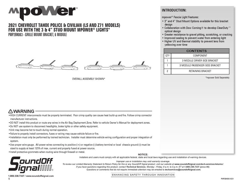
Soundoff Signal mpower PMP2BK003 User manual

Soundoff Signal

Soundoff Signal mpower PMP2BK003 User manual

Soundoff Signal EPL7PF C Series User manual
Soundoff Signal

Soundoff Signal EPL7PF C Series User manual

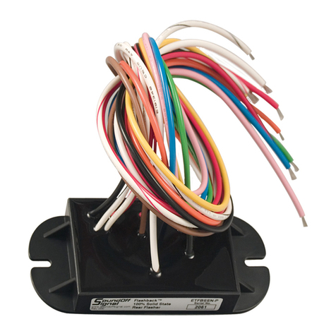
Soundoff Signal Mpower PMPSABK004 User manual
Soundoff Signal

Soundoff Signal Mpower PMPSABK004 User manual

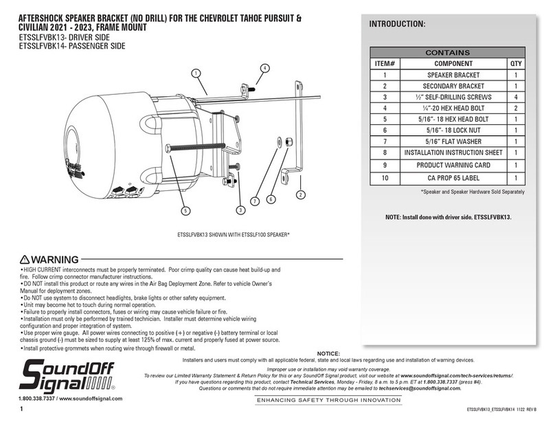
Soundoff Signal ETHFSS-NYPD-75 User manual
Soundoff Signal

Soundoff Signal ETHFSS-NYPD-75 User manual

Soundoff Signal ETSSLFVBK13 User manual
Soundoff Signal

Soundoff Signal ETSSLFVBK13 User manual

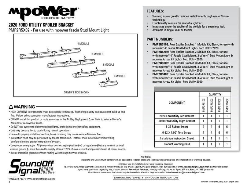
Soundoff Signal mpower PMP2RS 02 Series User manual
Soundoff Signal

Soundoff Signal mpower PMP2RS 02 Series User manual

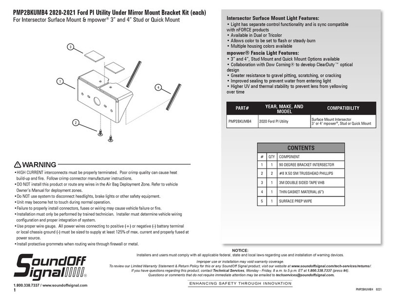
Soundoff Signal mpower Fascia 4 User manual
Soundoff Signal

Soundoff Signal mpower Fascia 4 User manual

Soundoff Signal nFORCE LED Interior Lightbar User manual
Soundoff Signal

Soundoff Signal nFORCE LED Interior Lightbar User manual

Soundoff Signal ETSSLFVBK11 User manual
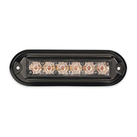
Soundoff Signal

Soundoff Signal ETSSLFVBK11 User manual

Soundoff Signal GHOST EGHST4 B Series User manual

Soundoff Signal

Soundoff Signal GHOST EGHST4 B Series User manual

Soundoff Signal PMP2BKUMB2 Series User manual
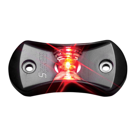
Soundoff Signal

Soundoff Signal PMP2BKUMB2 Series User manual

Soundoff Signal EFL1 User manual

Soundoff Signal

Soundoff Signal EFL1 User manual
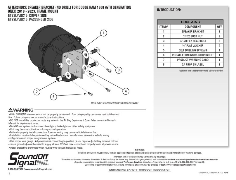
Soundoff Signal ETSSLFVBK15 User manual
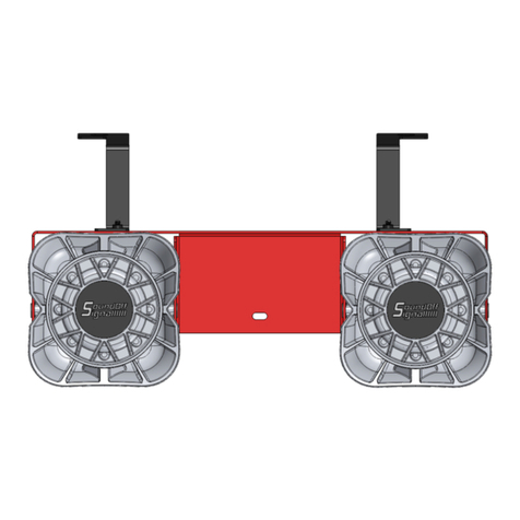
Soundoff Signal

Soundoff Signal ETSSLFVBK15 User manual

Soundoff Signal ETSSVBK04 User manual

Soundoff Signal

Soundoff Signal ETSSVBK04 User manual

Soundoff Signal GHOST EGHSTE5 B Series User manual
Soundoff Signal

Soundoff Signal GHOST EGHSTE5 B Series User manual

Soundoff Signal NEXUS nFORCE User manual
Soundoff Signal

Soundoff Signal NEXUS nFORCE User manual

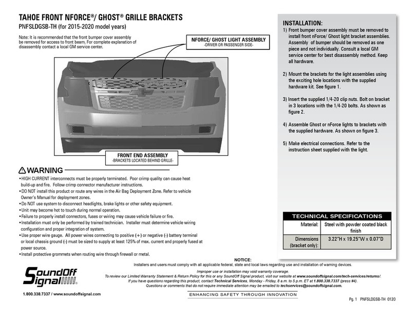
Soundoff Signal PNFSLDGSB-TH User manual
Soundoff Signal

Soundoff Signal PNFSLDGSB-TH User manual

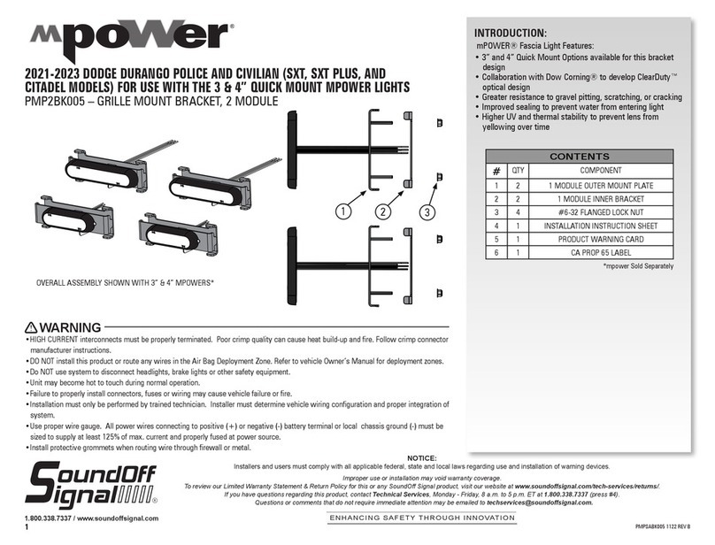
Soundoff Signal mPOWER PMP2BK005 User manual
Soundoff Signal

Soundoff Signal mPOWER PMP2BK005 User manual

Soundoff Signal ETSS100NBKTH User manual
Soundoff Signal

Soundoff Signal ETSS100NBKTH User manual

Soundoff Signal nROADS User manual

Soundoff Signal

Soundoff Signal nROADS User manual

Soundoff Signal bluePRINT SYNC User manual

Soundoff Signal

Soundoff Signal bluePRINT SYNC User manual

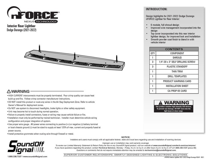
Soundoff Signal nFORCE Lightbar for Rear Interior User manual

Soundoff Signal

Soundoff Signal nFORCE Lightbar for Rear Interior User manual

Soundoff Signal UNIVERSAL UNDERCOVER ELUCTS010 User manual

Soundoff Signal

Soundoff Signal UNIVERSAL UNDERCOVER ELUCTS010 User manual

Soundoff Signal intersector ENT2B3 Series User manual

Soundoff Signal

Soundoff Signal intersector ENT2B3 Series User manual

Popular Automobile Accessories manuals by other brands

Air Lift Air Lift 1000 60713 installation guide

Air Lift

Air Lift Air Lift 1000 60713 installation guide

MediaTech U-DRIVE NAVIGATION user manual

MediaTech

MediaTech U-DRIVE NAVIGATION user manual

Pro-gard Products LLC. 3B300X installation guide

Pro-gard Products LLC.

Pro-gard Products LLC. 3B300X installation guide

Pet Gear TL9371CH instruction manual

Pet Gear

Pet Gear TL9371CH instruction manual

Silvercrest KH 2357 operating instructions

Silvercrest

Silvercrest KH 2357 operating instructions

ICON 91824E installation instructions

ICON

ICON 91824E installation instructions

MetaSystem 900000358 Installation Technical Sheet

MetaSystem

MetaSystem 900000358 Installation Technical Sheet

BuzzRack e-SCORPION 2 installation instructions
BuzzRack

BuzzRack e-SCORPION 2 installation instructions

FormFit HD 21D 06 quick guide

FormFit

FormFit HD 21D 06 quick guide

MaxiCosi TS375 instructions

MaxiCosi

MaxiCosi TS375 instructions

Park Safe PSC40 user manual

Park Safe

Park Safe PSC40 user manual

Power Fist 8985988 manual

Power Fist

Power Fist 8985988 manual

M-Power PMP2RS103 quick start guide

M-Power

M-Power PMP2RS103 quick start guide

Horn Tools HBRRF1613 Mounting instructions

Horn Tools

Horn Tools HBRRF1613 Mounting instructions

Speedtech 64-67 Instructional guide

Speedtech

Speedtech 64-67 Instructional guide

MetaSystem EasyPark User handbook

MetaSystem

MetaSystem EasyPark User handbook

Mixtelematics LTE External Modem quick start guide

Mixtelematics

Mixtelematics LTE External Modem quick start guide

MRHANDSFREE BC9000 user manual

MRHANDSFREE

MRHANDSFREE BC9000 user manual

manuals.online logo
manuals.online logoBrands
  • About & Mission
  • Contact us
  • Privacy Policy
  • Terms and Conditions

Copyright 2025 Manuals.Online. All Rights Reserved.