ACS ACR122U User manual

Subject to change without prior notice info@acs.com.hk
www.acs.com.hk
Application Programming Interface V2.04
ACR122U
USBNFCReader

ACR122U – Application Programming Interface info@acs.com.hk
Version 2.04 www.acs.com.hk
Page 2 of 49
Table of Contents
1.0. Introduction .............................................................................................................4
1.1. Features.................................................................................................................................4
1.2. USB Interface ........................................................................................................................5
2.0. Implementation........................................................................................................6
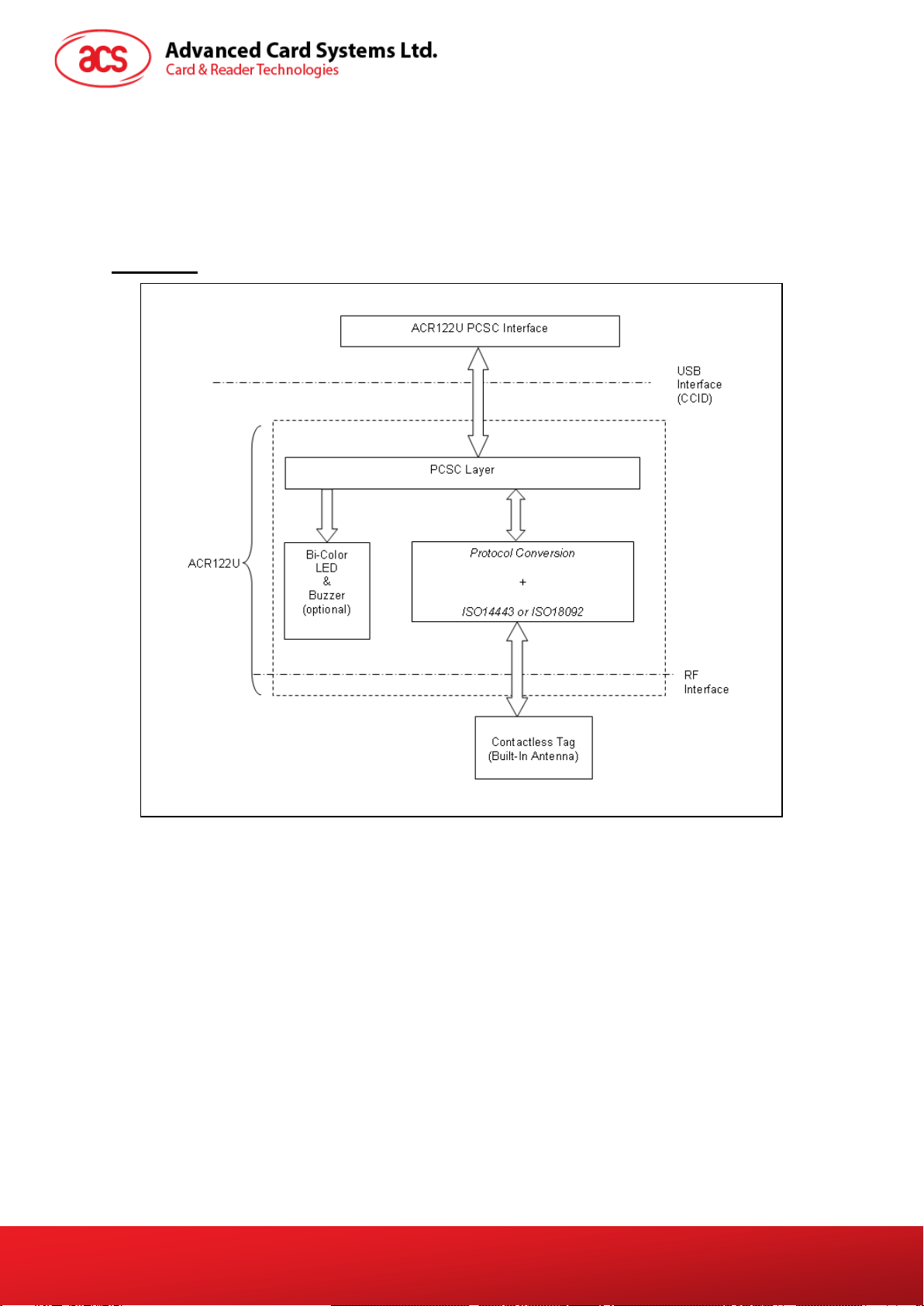
2.1. Communication Flow Chart of ACR122U..............................................................................6
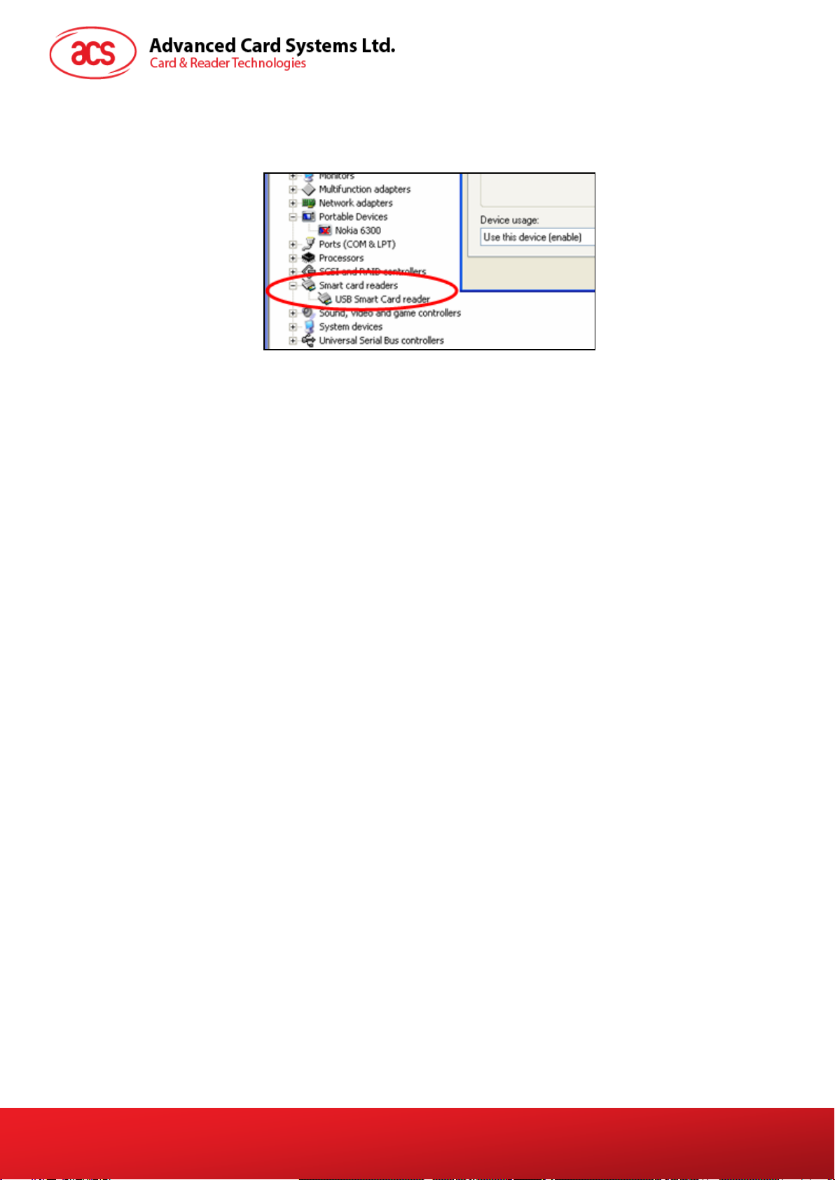
2.2. Smart Card Reader Interface Overview ................................................................................7
3.0. PICC Interface Description .....................................................................................8
3.1. ATR Generation.....................................................................................................................8
3.1.1. ATR format for ISO 14443 Part 3 PICCs......................................................................8
3.1.2. ATR format for ISO 14443 Part 4 PICCs......................................................................9
4.0. PICC Commands for General Purposes ..............................................................11
4.1. Get Data...............................................................................................................................11
5.0. PICC Commands (T=CL Emulation) for MIFARE Classic Memory Cards..........12
5.1. Load Authentication Keys....................................................................................................12
5.2. Authentication......................................................................................................................13
5.3. Read Binary Blocks .............................................................................................................16
5.4. Update Binary Blocks ..........................................................................................................17
5.5. Value Block Related Commands.........................................................................................18
5.5.1. Value Block Operation ................................................................................................18
5.5.2. Read Value Block........................................................................................................19
5.5.3. Restore Value Block....................................................................................................20
6.0. Pseudo-APDU Commands....................................................................................21
6.1. Direct Transmit ....................................................................................................................21
6.2. Bi-color LED and Buzzer Control.........................................................................................22
6.3. Get firmware version of the reader......................................................................................24
6.4. Get the PICC operating parameter......................................................................................25
6.5. Set the PICC operating parameter ......................................................................................26
6.6. Set Timeout Parameter........................................................................................................27
6.7. Set buzzer output during card detection..............................................................................28
7.0. Basic Program Flow for Contactless Applications .............................................29
7.1. How to access PC/SC-compliant tags (ISO 14443-4)?.......................................................31
7.2. How to access MIFARE DESFire tags (ISO 14443-4)? ......................................................32
7.3. How to access FeliCa tags (ISO 18092)? ...........................................................................34
7.4. How to access NFC Forum Type 1 Tags (ISO 18092)?......................................................35
7.5. Get the current setting of the contactless interface.............................................................37
Appendix A. ACR122U PC/SC Escape Command........................................................38
Appendix B. APDU Command and Response Flow for ISO 14443-Compliant Tags..41
Appendix C. APDU command and response flow for ISO 18092–compliant tags .....42
Appendix D. Error Codes...............................................................................................43
Appendix E. Sample codes for setting the LED ...........................................................45
List of Figures
Figure 1 : Communication Flow Chart of ACR122U ..............................................................................6
Figure 2 : Smart Card Reader Interface on the Device Manager ..........................................................7

ACR122U – Application Programming Interface info@acs.com.hk
Version 2.04 www.acs.com.hk
Page 3 of 49
Figure 3 : Basic Program Flow for Contactless Applications...............................................................29
Figure 4 : Topaz Memory Map.............................................................................................................36
List of Tables
Table 1 : USB Interface ..........................................................................................................................5
Table 2 : ATR format for ISO 14443 Part 3 PICCs.................................................................................8
Table 3 : ATR format for ISO 14443 Part 4 PICCs.................................................................................9
Table 4 : MIFARE 1K Memory Map......................................................................................................14
Table 5 : MIFARE Classic 4K Memory Map.........................................................................................14
Table 6 : MIFARE Ultralight Memory Map............................................................................................15
Table 7 : Error Codes ...........................................................................................................................44

Version 2.04 www.acs.com.hk
Page 4 of 49
1.0.Introduction
The ACR122U is a PC-linked contactless smart card reader/writer used for accessing ISO 14443-4
Type A and Type B, MIFARE®, ISO 18092, and FeliCa tags. The ACR122U is PC/SC compliant
making it compatible with existing PC/SC applications.
The ACR122U serves as the intermediary device between the computer and the contactless tag via
the USB interface. The reader carries out the command from the computer whether the command is
used to communicate with a contactless tag, or control the device peripherals (LED or buzzer). This
API document will discuss in detail how the PC/SC commands were implemented for the contactless
interface and device peripherals of the ACR122U.
1.1. Features
•USB 2.0 Full Speed Interface
•CCID Compliance
•Smart Card Reader:
oRead/Write speed of up to 424 Kbps
oBuilt-in antenna for contactless tag access, with card reading distance of up to 50 mm
(depending on tag type)
oSupport for ISO 14443 Part 4 Type A and B cards, MIFARE, FeliCa, and all four types of
NFC (ISO/IEC 18092 tags)
oBuilt-in anti-collision feature (only one tag is accessed at any time)
oApplication Programming Interface:
oSupports PC/SC
oSupports CT-API (through wrapper on top of PC/SC)
oBuilt-in Peripherals:
oUser-controllable bi-color LED
oUser-controllable buzzer
oSupports Android™ 3.1 and above
oCompliant with the following standards:
oIEC/EN 60950
oISO 18092
oISO 14443
oCE
oFCC
oKC
oVCCI
oMIC
oPC/SC
oCCID
oMicrosoft® WHQL
oRoHS 2

ACR122U – Application Programming Interface info@acs.com.hk
Version 2.04 www.acs.com.hk
Page 5 of 49
1.2. USB Interface
The ACR122U is connected to a computer through USB as specified in the USB Specification 1.1.
The ACR122U is working in full-speed mode, i.e. 12 Mbps.
Pin Signal Function
1 VBUS +5 V power supply for the reader (Max. 200 mA, Normal 100 mA)
2 D- Differential signal transmits data between ACR122U and PC
3 D+ Differential signal transmits data between ACR122U and PC
4 GND Reference voltage level for power supply
Table 1: USB Interface

Version 2.04 www.acs.com.hk
Page 6 of 49
2.0.Implementation
2.1. Communication Flow Chart of ACR122U
The Standard Microsoft CCID and PC/SC drivers are used; thus, no ACS drivers are required
because the drivers are already built inside the Windows® operating system. Your computer’s registry
settings can also be modified to be able to use the full capabilities of the ACR122U NFC Reader. See
Appendix A for more details.
Figure 1: Communication Flow Chart of ACR122U

ACR122U – Application Programming Interface info@acs.com.hk
Version 2.04 www.acs.com.hk
Page 7 of 49
2.2. Smart Card Reader Interface Overview
Go to the Device Manager to see the “ACR122U PICC Interface.” The standard Microsoft USB CCID
Driver should be used.
Figure 2: Smart Card Reader Interface on the Device Manager

ACR122U – Application Programming Interface info@acs.com.hk
Version 2.04 www.acs.com.hk
Page 8 of 49
3.0.PICC Interface Description
3.1. ATR Generation
If the reader detects a PICC, an ATR will be sent to the PC/SC driver for identifying the PICC.
3.1.1. ATR format for ISO 14443 Part 3 PICCs
Byte Value
(Hex) Designation Description
0 3Bh Initial Header -
1 8Nh T0
Higher nibble 8 means: no TA1, TB1, TC1
only TD1 is following.
Lower nibble N is the number of historical
bytes (HistByte 0 to HistByte N-1)
2 80h TD1 Higher nibble 8 means: no TA2, TB2, TC2
only TD2 is following.
Lower nibble 0 means T = 0
3 01h TD2 Higher nibble 0 means no TA3, TB3, TC3,
TD3 following.
Lower nibble 1 means T = 1
4
To
3+N
80h T1 Category indicator byte, 80 means A status
indicator may be present in an optional
COMPACT-TLV data object
4Fh
Tk
Application identifier Presence Indicator
0Ch Length
RID Registered Application Provider Identifier
(RID) # A0 00 00 03 06h
SS Byte for standard
C0 .. C1h Bytes for card name
00 00 00 00h RFU RFU # 00 00 00 00h
4+N UUh TCK Exclusive-oring of all the bytes T0 to Tk
Table 2: ATR format for ISO 14443 Part 3 PICCs
Example:
ATR for MIFARE 1K = {3B 8F 80 01 80 4F 0C A0 00 00 03 06 03 00 01 00 00 00 00 6Ah}
ATR
Initial
Header T0 TD1 TD2 T1 Tk Length RID Standard Card
Name RFU TCK
3Bh 8Fh 80h 01h 80h 4Fh 0Ch A0 00
00 03
06h 03h 00 01h 00 00
00 00h 6Ah

ACR122U – Application Programming Interface info@acs.com.hk
Version 2.04 www.acs.com.hk
Page 9 of 49
Where:
Length (YY) = 0Ch
RID = A0 00 00 03 06h(PC/SC Workgroup)
Standard (SS) = 03h (ISO 14443A, Part 3)
Card Name (C0 .. C1) = [00 01h] (MIFARE Classic® 1K)
Where, Card Name (C0 .. C1)
00 01h: MIFARE Classic 1K
00 02h: MIFARE Classic 4K
00 03h: MIFARE® Ultralight®
00 26h: MIFARE Mini
F0 04h: Topaz and Jewel
F0 11h: FeliCa 212K
F0 12h: FeliCa 424K
FFh [SAK]: Undefined
3.1.2. ATR format for ISO 14443 Part 4 PICCs
Byte Value (Hex) Designation Description
0 3Bh Initial Header -
1 8Nh T0
Higher nibble 8 means: no TA1, TB1, TC1
only TD1 is following.
Lower nibble N is the number of historical
bytes (HistByte 0 to HistByte N-1)
2 80h TD1 Higher nibble 8 means: no TA2, TB2, TC2
only TD2 is following.
Lower nibble 0 means T = 0
3 01h TD2 Higher nibble 0 means no TA3, TB3, TC3,
TD3 following.
Lower nibble 1 means T = 1
4
to
3 + N
XXh T1 Historical Bytes:
ISO 14443A:
The historical bytes from ATS response. Refer
to the ISO14443-4 specification.
ISO 14443B:
The higher layer response from the ATTRIB
response (ATQB). Refer to the ISO14443-3
specification.
XXh
XX
XXh Tk
4+N UUh TCK Exclusive-oring of all the bytes T0 to Tk
Table 3: ATR format for ISO 14443 Part 4 PICCs

ACR122U – Application Programming Interface info@acs.com.hk
Version 2.04 www.acs.com.hk
Page 10 of 49
We take for example, an ATR for DESFire, which is:
DESFire (ATR) = 3B 86 80 01 06 75 77 81 02 80 00h
ATR
Initial Header T0 TD1 TD2 ATS
T1 Tk TCK
3Bh 86h 80h 01h 06h 75 77 81 02 80h 00h
This ATR has 6 bytes of ATS, which is: [06 75 77 81 02 80h]
Note: Use the APDU “FF CA 01 00 00h” to distinguish the ISO 14443A-4 and ISO 14443B-4 PICCs,
and retrieve the full ATS if available. The ATS is returned for ISO14443A-3 or ISO14443B-3/4 PICCs.
Another example would be the ATR for ST19XRC8E, which is:
ST19XRC8E (ATR) = 3B 8C 80 01 50 12 23 45 56 12 53 54 4E 33 81 C3 55h
ATR
Initial Header T0 TD1 TD2 ATQB
T1 Tk TCK
3Bh 86h 80h 01h 50h 12 23 45 56 12 53 54 4E 33 81 C3h 55h
Since this card follows ISO 14443 Type B, the response would be ATQB which is 50 12 23 45 56 12
53 54 4E 33 81 C3h is 12 bytes long with no CRC-B
Note: You can refer to the ISO7816, ISO14443 and PC/SC standards for more details.

ACR122U – Application Programming Interface info@acs.com.hk
Version 2.04 www.acs.com.hk
Page 11 of 49
4.0. PICC Commands for General Purposes
4.1. Get Data
This command returns the serial number or ATS of the connected PICC.
Get UID APDU Format (5 bytes)
Command Class INS P1 P2 Le
Get Data FFh CAh 00h
01h 00h 00h
(Full Length)
Get UID Response Format (UID + 2 bytes) if P1 = 00h
Response Data Out
Result UID
(LSB) - - UID
(MSB) SW1 SW2
Get ATS of a ISO 14443 A card (ATS + 2 bytes) if P1 = 01h
Response Data Out
Result ATS SW1 SW2
Response Codes
Results SW1 SW2 Meaning
Success 90 00h The operation completed successfully.
Error 63 00h The operation failed.
Error 6A 81h Function not supported.
Example:
1. To get the serial number of the connected PICC.
UINT8 GET_UID[5]={FFh, CAh, 00h, 00h, 04h};
2. To get the ATS of the connected ISO 14443 A PICC.
UINT8 GET_ATS[5]={FFh, CAh, 01h, 00h, 04h};

ACR122U – Application Programming Interface info@acs.com.hk
Version 2.04 www.acs.com.hk
Page 12 of 49
5.0. PICC Commands (T=CL Emulation) for MIFARE Classic
Memory Cards
5.1. Load Authentication Keys
This command loads the authentication keys into the reader. The authentication keys are used to
authenticate the particular sector of the MIFARE Classic 1K/4K memory card. Volatile authentication
key location is provided.
Load Authentication Keys APDU Format (11 bytes)
Command Class INS P1 P2 Lc Data In
Load Authentication Keys FFh 82h Key Structure Key Number 06h Key (6 bytes)
Where:
Key Structure 1 byte.
00h = Key is loaded into the reader volatile memory.
Other = Reserved.
Key Number 1 byte.
00h ~ 01h = Key Location. The keys will disappear once the reader is
disconnected from the PC.
Key6 bytes.
The key value loaded into the reader. e.g., {FF FF FF FF FF FFh}
Load Authentication Keys Response Format (2 Bytes)
Response Data Out
Result SW1 SW2
Response Codes
Results SW1 SW2 Meaning
Success 90 00h The operation completed successfully.
Error 63 00h The operation failed.
Example:
Load a key {FF FF FF FF FF FFh} into the key location 00h.
APDU = {FF 82 00 00h 06 FF FF FF FF FF FFh}

ACR122U – Application Programming Interface info@acs.com.hk
Version 2.04 www.acs.com.hk
Page 13 of 49
5.2. Authentication
This command uses the keys stored in the reader to do authentication with the MIFARE 1K/4K card
(PICC). Two types of authentication keys are used: TYPE_A and TYPE_B.
Load Authentication Keys APDU Format (6 bytes) [Obsolete]
Command Class INS P1 P2 P3 Data In
Authentication FFh 88h 00h Block Number Key Type Key Number
Load Authentication Keys APDU Format (10 bytes)
Command Class INS P1 P2 Lc Data In
Authentication FFh 86h 00h 00h 05h Authenticate Data Bytes
Authenticate Data Bytes (5 bytes)
Byte1 Byte 2 Byte 3 Byte 4 Byte 5
Version 01h 00h Block Number Key Type Key Number
Where:
Block Number 1 byte. This is the memory block to be authenticated.
Key Type 1 byte
60h = Key is used as a TYPE A key for authentication.
61h = Key is used as a TYPE B key for authentication.
Key Number 1 byte
00h ~ 01h = Key Location.
Note: For MIFARE Classic 1K Card, it has totally 16 sectors and each sector consists of 4
consecutive blocks. E.g. Sector 00h consists of Blocks {00h, 01h, 02h and 03h}; Sector 01h consists
of Blocks {04h, 05h, 06h and 07h}; the last sector 0F consists of Blocks {3Ch, 3Dh, 3Eh and 3Fh}.
Once the authentication is done successfully, there is no need to do the authentication again if the
blocks to be accessed belong to the same sector. Please refer to the MIFARE Classic 1K/4K
specification for more details.
Load Authentication Keys Response Format (2 bytes)
Response Data Out
Result SW1 SW2
Response Codes
Results SW1 SW2 Meaning
Success 90 00h The operation completed successfully.
Error 63 00h The operation failed.

ACR122U – Application Programming Interface info@acs.com.hk
Version 2.04 www.acs.com.hk
Page 14 of 49
Sectors
(Total 16 sectors. Each
sector consists of 4
consecutive blocks)
Data Blocks
(3 blocks, 16 bytes per
block)
Trailer Block
(1 block, 16 bytes)
Sector 0 00h ~ 02h 03h
Sector 1 04h ~ 06h 07h
..
..
Sector 14 38h ~ 0Ah 3Bh
Sector 15 3Ch ~ 3Eh 3Fh
Table 4: MIFARE 1K Memory Map
Sectors
(Total 32 sectors. Each
sector consists of 4
consecutive blocks)
Data Blocks
(3 blocks, 16 bytes per
block)
Trailer Block
(1 block, 16 bytes)
Sector 0 00h ~ 02h 03h
Sector 1 04h ~ 06h 07h
..
..
Sector 30 78h ~ 7Ah 7Bh
Sector 31 7Ch ~ 7Eh 7Fh
Sectors
(Total 8 sectors. Each
sector consists of 16
consecutive blocks)
Data Blocks
(15 blocks, 16 bytes
per block)
Trailer Block
(1 block, 16 bytes)
Sector 32 80h ~ 8Eh 8Fh
Sector 33 90h ~ 9Eh 9Fh
..
..
Sector 38 E0h ~ EEh EFh
Sector 39 F0h ~ FEh FFh
Table 5: MIFARE Classic 4K Memory Map
1 KB
2 KB
2 KB

ACR122U – Application Programming Interface info@acs.com.hk
Version 2.04 www.acs.com.hk
Page 15 of 49
Byte Number 0 1 2 3 Page
Serial Number SN0 SN1 SN2 BCC0 0
Serial Number SN3 SN4 SN5 SN6 1
Internal/Lock BCC1 Internal Lock0 Lock1 2
OTP OPT0 OPT1 OTP2 OTP3 3
Data read/write Data0 Data1 Data2 Data3 4
Data read/write Data4 Data5 Data6 Data7 5
Data read/write Data8 Data9 Data10 Data11 6
Data read/write Data12 Data13 Data14 Data15 7
Data read/write Data16 Data17 Data18 Data19 8
Data read/write Data20 Data21 Data22 Data23 9
Data read/write Data24 Data25 Data26 Data27 10
Data read/write Data28 Data29 Data30 Data31 11
Data read/write Data32 Data33 Data34 Data35 12
Data read/write Data36 Data37 Data38 Data39 13
Data read/write Data40 Data41 Data42 Data43 14
Data read/write Data44 Data45 Data46 Data47 15
Table 6: MIFARE Ultralight Memory Map
Example:
1. To authenticate the Block 04hwith a {TYPE A, key number 00h}. For PC/SC V2.01, Obsolete.
APDU = {FF 88 00 0460 00h};
2. To authenticate the Block 04hwith a {TYPE A, key number 00h}. For PC/SC V2.07
APDU = {FF 86 00 00 05 01 00 04 60 00h}
Note: MIFARE Ultralight does not need to do any authentication. The memory is free to access.
512 bits
or
64 bytes

ACR122U – Application Programming Interface info@acs.com.hk
Version 2.04 www.acs.com.hk
Page 16 of 49
5.3. Read Binary Blocks
This command retrieves the data blocks from the PICC. The data block/trailer block must be
authenticated first.
Read Binary APDU Format (5 bytes)
Command Class INS P1 P2 Le
Read Binary Blocks FFh B0h 00h Block Number Number of Bytes to Read
Where:
Block Number 1 byte
The block to be accessed.
Number of Bytes to Read 1 byte
Maximum 16 bytes.
Read Binary Block Response Format (N + 2 bytes)
Response Data Out
Result 0 <= N <= 16 SW1 SW2
Response Codes
Results SW1 SW2 Meaning
Success 90 00h The operation completed successfully.
Error 63 00h The operation failed.
Example:
1. Read 16 bytes from the binary block 04h(MIFARE Classic 1K or 4K)
APDU = {FF B0 00 04 10h}
2. Read 4 bytes from the binary Page 04h(MIFARE Ultralight)
APDU = {FF B0 00 04 04h}
3. Read 16 bytes starting from the binary Page 04h(MIFARE Ultralight) (Pages 4, 5, 6 and 7
will be read)
APDU = {FF B0 00 04 10h}
Note: Please add a 2-second delay when reading NDEF messages in MIFARE Classic 4K cards.

ACR122U – Application Programming Interface info@acs.com.hk
Version 2.04 www.acs.com.hk
Page 17 of 49
5.4. Update Binary Blocks
This command writes data blocks into the PICC. The data block/trailer block must be authenticated.
Update Binary APDU Format (4 or 16 + 5 bytes)
Command Class INS P1 P2 Lc Data In
Update Binary
Blocks FFh D6h 00h Block
Number
Number of
Bytes to
Update
Block Data
4 Bytes for MIFARE Ultralight or
16 Bytes for MIFARE 1K/4K
Where:
Block Number 1 byte
The starting block to be updated.
Number of Bytes to Update 1 byte
16 bytes for MIFARE 1K/4K
4 bytes for MIFARE Ultralight
Block Data 4 bytes or 16 bytes.
The data to be written into the binary block/blocks.
Response Codes
Results SW1 SW2 Meaning
Success 90 00h The operation completed successfully.
Error 63 00h The operation failed.
Example:
1. Update the binary block 04hof MIFARE Classic 1K/4K with Data {00 01 .. 0Fh}
APDU = {FF D6 00 04 10 00 01 02 03 04 05 06 07 08 09 0A 0B 0C 0D 0E 0Fh}
2. Update the binary block 04hof MIFARE Ultralight with Data {00 01 02 03}
APDU = {FF D6 00 04 04 00 01 02 03h}

ACR122U – Application Programming Interface info@acs.com.hk
Version 2.04 www.acs.com.hk
Page 18 of 49
5.5. Value Block Related Commands
The data block can be used as value block for implementing value-based applications.
5.5.1. Value Block Operation
This command manipulates the value-based transactions (e.g., increment a value of the value block
etc.)
Value Block Operation APDU Format (10 bytes)
Command Class INS P1 P2 Lc Data In
Value Block
Operation FFh D7h 00h Block
Number 05h VB_OP VB_Value
(4 bytes)
{MSB .. LSB}
Where:
Block Number 1 byte
The value block to be manipulated.
VB_OP 1 byte
00h = Store the VB_Value into the block. The block will then be
converted to a value block.
01h = Increment the value of the value block by the VB_Value. This
command is only valid for value block.
02h = Decrement the value of the value block by the VB_Value. This
command is only valid for value block.
VB_Value 4 bytes.
The value used for value manipulation. The value is a signed long integer
(4 bytes).
Example 1: Decimal –4 = {FFh, FFh, FFh, FCh}
VB_Value
MSB LSB
FFh FFh FFh FCh
Example 2: Decimal 1 = {00h, 00h, 00h, 01h}
VB_Value
MSB LSB
00h 00h 00h 01h
Value Block Operation Response Format (2 bytes)
Response Data Out
Result SW1 SW2

ACR122U – Application Programming Interface info@acs.com.hk
Version 2.04 www.acs.com.hk
Page 19 of 49
Response Codes
Results SW1 SW2 Meaning
Success 90 00h The operation completed successfully.
Error 63 00h The operation failed.
5.5.2. Read Value Block
This command retrieves the value from the value block. This command is only valid for value block.
Read Value Block APDU Format (5 bytes)
Command Class INS P1 P2 Le
Read Value Block FFh B1h 00h Block Number 04h
Where:
Block Number 1 byte
The value block to be accessed.
Read Value Block Response Format (4 + 2 bytes)
Response Data Out
Result Value
{MSB .. LSB} SW1 SW2
Where:
Value 4 bytes.
The value returned from the card. The value is a signed long integer (4 bytes).
Example 1: Decimal –4 = {FFh, FFh, FFh, FCh}
Value
MSB LSB
FFh FFh FFh FCh
Example 2: Decimal 1 = {00h, 00h, 00h, 01h}
Value
MSB LSB
00h 00h 00h 01h
Response Codes
Results SW1 SW2 Meaning
Success 90 00h The operation completed successfully.
Error 63 00h The operation failed.

ACR122U – Application Programming Interface info@acs.com.hk
Version 2.04 www.acs.com.hk
Page 20 of 49
5.5.3. Restore Value Block
This command copies a value from a value block to another value block.
Restore Value Block APDU Format (7 bytes)
Command Class INS P1 P2 Lc Data In
Restore Value Block FFh D7h 00h Source Block Number 02h 03h Target Block
Number
Where:
Source Block Number 1 byte
The value of the source value block will be copied to the target
value block.
Target Block Number 1 byte
The value block to be restored. The source and target value
blocks must be in the same sector.
Restore Value Block Response Format (2 bytes)
Response Data Out
Result SW1 SW2
Response Codes
Results SW1 SW2 Meaning
Success 90 00h The operation completed successfully.
Error 63 00h The operation failed.
Example:
1. Store a value “1” into block 05h
APDU = {FF D7 00 05 05 00 00 00 00 01h}
Answer: 90 00h
2. Read the value block 05h
APDU = {FF B1 00 05 00h}
Answer: 00 00 00 01 90 00h [9000h]
3. Copy the value from value block 05hto value block 06h
APDU = {FF D7 00 05 02 03 06h}
Answer: 90 00h [9000h]
4. Increment the value block 05hby “5”
APDU = {FF D7 00 05 05 01 00 00 00 05h}
Answer: 90 00h [9000h]
Other manuals for ACR122U
5
Table of contents
Other ACS Card Reader manuals
Popular Card Reader manuals by other brands

UniFlow
UniFlow micard plus installation manual

Star Micronics
Star Micronics TCP300 Series Features

Rosslare
Rosslare AY-x20 Series installation manual

AMAG Technology
AMAG Technology S840 Installation and user instructions

Diehl Metering
Diehl Metering IZAR OH BT 2 user guide

Sonnet
Sonnet Qio MR Professional Universal Media Reader &... user guide