Actall PALS 9K User manual

PALS 9K | Installation Manual
Version 4.0
www.actall.com

Copyright © 2018 Actall Corporation | www.actall.com
2
©Copyright 2018 by Actall Corporation®. All rights reserved. Crisis
Controller©™ is a registered trademark of Actall Corporation. (U.S.
Patent No.: 5,708,417) MicrosoftP®P and WindowsP®P are registered
trademarks of MicrosoftP®P Corporation. Crisis Controller©™P Version
5.00 software and documentation developed by Actall Corporation®,
Denver, Colorado. (TUwww.actall.comUT) This manual is subject to
change and may not be reproduced in any way or form, electronic or
mechanical.
Software License Agreement:
The use of this software product is limited to the terms and conditions
below. Use by the purchaser of Crisis Controller©™ Alarm Monitoring
software indicates acceptance of these terms.
Grant of Rights:
This software may only be used on the computers for which it is licensed.
This license may not be transferred from its original site. You may not
copy or otherwise distribute this software, except to make a backup
copy. You may not modify, alter, or transfer the software in any way.
Limitation of Liability:
Licensor shall not be liable for any claim or demand by Licensee for
damages of any kind, including, but not limited to special, general,
incidental, direct or consequential dam-ages, for loss of business
prots, business interruption, loss of business information, or any other
pecuniary loss arising out of the subject matter of this agreement Some
jurisdictions do not allow excluding or limiting implied warranties or
limiting liability or consequential damages, and some jurisdictions have
special statutory consumer protection provisions that may supersede
this limitation. As a result, this limitation of liability may not apply to you
if prohibited by the laws of your jurisdiction.
General:
Any violation of this Agreement is subject to criminal and civil prosecution.
If any provision is found to be unlawful, void, or unenforceable, then that
provision shall be severed from this Agreement and will not aect the
validity and enforceability of any of the remaining provisions. The laws of
the State of Colorado shall govern this Agreement.
COPYRIGHT & LIMITATIONS CONTACT
Inquiries should be
directed to:
Actall Corporation
2017 Curtis Street
Denver, CO 80205
Phone:
303-226-4799
Toll-free:
1-800-598-1745
For technical support,
please call us direct
during regular
business hours
(Monday through
Friday, 8:00 a.m. to
5:00 p.m. Mountain
Standard Time) or
Emai us 24/7.
303-226-4799

INSTALLATION MANUAL OVERVIEW......................................................................... ............ 4
Crisis Controller©™ Center .................................................................................... 4
Equipment ............................................................................................................... 4
How Transmiers Communicate with Receivers ..................................................... 4
Personal Mobile Transmiers ................................................................................. 4
How IRT Locators Communicate with PMTs............................................................. 6
INSTALLING THE SOFTWARE AND HARDWARE .................................................................... 7
Minimum Computer System Requirements............................................................. 7
How to Install the Soware ..................................................................................... 7
CRISIS CONTROLLER©™ NETWORKING ............................................................................... 9
Dedicated Network Soware Installaon................................................................ 9
Peer-To-Peer Soware Installaon .......................................................................... 9
CRISIS CONTROLLER©™ HARDWARE.................................................................................... 11
Hardware Key........................................................................................................... 11
Serial Watchdog ...................................................................................................... 11
Serial Receiver ......................................................................................................... 13
Repeaters................................................................................................................. 13
Input /Output Module (SIO32)................................................................................ 14
Paging ......................................................................................................................16
Printer...................................................................................................................... 16
Wireless Transmiers .............................................................................................. 16
IRTs, PMTs, and Wireless RF Locators ...................................................................... 17
IRT Locators ............................................................................................................. 17
Tesng IRT Locators ................................................................................................. 18
Wireless RF Locators (RFL) ...................................................................................... 20
MAINTAINING THE CRISIS CONTROLLER©™ ........................................................................ 22
Troubleshoong....................................................................................................... 22
Transmier Problems .............................................................................................. 22
PMTs........................................................................................................................ 22
Receiver/Repeater Problems................................................................................... 22
IRTs 19...................................................................................................................... 22
SPECIFICATIONS.................................................................................................................... 23
PMT Specicaons................................................................................................... 23
Lapel Specicaons..................................................................................... ............ 23
IRT-M Specicaons................................................................................................. 23
IRT-S Specicaons ..................................................................................................23
SIO32 Specicaons ................................................................................................ 23

PALS Installaon Manual
INSTALLATION MANUAL OVERVIEW
The Crisis Controller©™ Alert Monitoring Center receives and supervises alarm informaon from wireless security
devices and transmiers. Data from these devices is processed by the soware and displayed to rapid response
to alarms and trouble condions.
The PALS©® Alert Monitoring Center consists of a central monitoring computer, which receives data from
wireless 900MHz transmiers through a serial receiver. Numerous types of transmiers are available, including
xed-posion contact sensors, moon and smoke detectors, and personal alarm transmiers. The soware can
also process signals from Actall Security Product’s® Personal Alarm Locang System (PALS©®), which transmits
locaon data from xed posion infrared (IR) Locators to The transmiers then communicate their locaon to the
Monitoring Staon, allowing Control Operators to track and locate posions of the individuals wearing the mobile
alarm devices.
Wireless transmiers send coded digital messages to the serial receiver(s). These messages contain data idenfying
the transmier and its status. Mulple transmissions of this data over the 902 to 928 MHz frequency range help
prevent signal interference and ensure that the signal is received.
Serial Receiver(s) idenfy valid messages, decodes them, and transmits that data to the
Crisis Controller©™ soware for alarm annunciaon on the Alarm Monitoring PC.
Most sites require the use of wireless repeaters: 900MHz transceivers (powered by 14VAC)
that idenfy valid transmissions and re-transmit them at full signal strength. Repeaters
provide a method of extending eecve transmission ranges and of providing mulple,
redundant transmission paths between transmiers and receivers.
Serial Receiver
The Personal Mobile Transmiers (PMTs) used with the PALS©® systems work in conjuncon with IRT Locators to
provide detailed informaon of locaon and movement. PMTs store the two most recently received IRT Locator
codes. When an alarm is sent, this data is sent along with the alarm status to a serial receiver aached to the
Monitoring Center PC. If a PMT remains within the coverage area of the same Locator for a longer period of me,
the programmer can increase the me interval between PMT readings. This reduces current consumpon and
increases baery life. Among the features of the PMT is the capability to monitor movement from locator to locator.
A Guard Tour feature permits the system to monitor the me between arrivals at locaons on a predetermined
route, so that signicant variaons from the route and mes of transit can create alarms. Actall oers two PMT
versions: the PALS 9000 and the L2L.

5
PALS Installaon Manual
INSTALLATION MANUAL OVERVIEW (continued)
Push Buon Alarm acvaon
Baery compartment/Reset switch: Aer a baery is installed in the PMT, the reset switch must be pressed. The
switch is located inside the baery compartment, insid the cover above the baery holder.
Lapel Reader Accessory: The Lapel Reader is an infrared detector that may be plugged into the programming
jack of the PMT and threaded through clothing that may inadvertently cover the PMT. The Lapel Reader has
approximately the same IR sensivity as the PMT and can be used to enhance IRT Locator recepon. If the PMT
must be worn under clothing, the Lapel Reader will funcon as a remote receiver for the PMT.
PMTs are powered by a disposable, 3V Lithium Ion baery. Typical baery life is 6 – 9 months for the PALS 9000
units and 4 – 6 months for the L2L, The L2L’s baery life is less due to the addional IR Recevier circuitry in that
model.
Lapel Reader PMT Baery
Compartment and Reset

6
PALS Installaon Manual
INSTALLATION MANUAL OVERVIEW (continued)
• Pull Cord Alarm acvaon
• Man Down Alarm acvaon (internal lt switch)
• 3-funcon slide switches on side:
Posion 1 (boom) = Turns IR reader O (supervision connues).
Posion 2 (middle) = Enables all features except Man Down.
Posion 3 (top) = Enables all features.
Operaonal procedures should be set in place to test the operaon of PMTs and IRTs on
a regular basis.
Infrared transmiers (IRTs) send coded digital messages to an infrared receiver. Each message contains data
idenfying the IRT Locator ID. IRTs should be ceiling mounted on opposite sides of ingress/egress points between
secure zones and/or in larger areas where locaon informaon is desired. Each IRT is powered by 12VDC and has a
draw of 155ma. They are oen set up in series from an aggregate DC power supply. Each PMT contains an Infrared
receiver that reads valid IRT messages and decodes them. The locaon informaon is stored and rebroadcast via
the radio frequency (RF) 900MHz transmier.

7
PALS Installaon Manual
1.5 gHz Penum 4 with 256MB RAM, 20GB hard drive, 48X CD ROM, 2 to 8 serial ports
PS2, or bus mouse
17” SVGA
Oponal (parallel port required)
Oponal (parallel port required)
Oponal
Oponal (100Mb connecons recommended)
The Crisis Controller©™ soware comes on a CD and can be used for either a new installaon or upgrade of a
previous version.
Prior to a new installaon or upgrade of the Crisis Controller©™ soware, verify that
Crisis Controller©™ is not running, or in the process of upgrading either on the current
machine or on a machine aached via the network. Irrevocable damage to your data
may result.
• Insert the CD into the drive.
• From the “Run” command, type “d:\setup” where “d” is the leer of the diskee drive.
The Setup program will assist you step-by-step in the installaon or upgrade of the Crisis Controller©™ soware.
Please carefully read and follow the instrucons during the installaon. Once the quesons are answered, the
installaon of the Crisis Controller©™ soware will proceed automacally.

8
PALS Installaon Manual
(continued)
When upgrading from previous versions of Crisis Controller©™ soware, some
informaon cannot be converted due to limitaons of current version. This
informaon will have to be re-entered to maintain an idencal system. You
should consult an Actall Support Technician prior to upgrading any version of Crisis
controller soware.
The Setup program will prompt you for the directory where the Crisis Controller©™ les will be installed. If this
is an upgrade, select the same directory as the previously installed Crisis Controller©™ soware, this permits the
appropriate les to be backed up as well as translated for ulizaon in the new soware.
If this is a network installaon, make sure the le server drive has been selected
(i.e. F:\Program Files\Alert).
When you are ready to proceed, select Next. At any me you may select Cancel to abort the installaon.
When the installaon is complete, a le directory will have been created (the default directory is \Program Files\
Alert) as well as a Start Menu (the default start menu is Programs\Crisis Controller\Crisis Controller). You may
place a Quick Start icon for Crisis Controller©™ on your Desktop. To do this, open the directory containing the
program. Rightclick on the Alert icon. Select Create Shortcut, then drag the icon onto your desktop. See your
Windows® instrucon guide for further details.

PALS Installaon Manual
The Crisis Controller©™ soware can be networked either peer-to-peer or using a dedicated le server. In either
case, each machine on the network running Crisis Controller©™ must have an Alert Monitoring Hardware Key
installed at all mes.
All Hardware Keys must remain on the machines where they were inially installed and never relocated or
removed for any reason. Doing so will cause undesired results and void all warranes implied or otherwise, unless
specically directed by Actall® Technical Support.
If you are unfamiliar with your operang system or you are unfamiliar with the
intricacies of the network being used, please do not aempt to use the network
funcon of the Crisis Controller©™. Doing so may cause permanent damage to your
Crisis Controller©™ data les. Network installaons should only be done by trained
Network Technicians.
All connecons in a Crisis Controller©™ networked system should be capable of no less
than 100 Mb. In addion, all machines should be connected using a hub (or switch)
rated at no less than 100 Mb.
The following is a guide for establishing the Crisis Controller Network only. All Network
Hardware (Network cards and Hub/Switch) and appropriate drivers should be
installed and their operaon veried prior to proceeding to the Network setup for
Crisis Controller. For instrucons on establishing a peer-to-peer or client/server
network, consult the required documentaon on operang system being used for this
conguraon.
A peer-to-peer network is the most common method used for
PALS installaons. The network hardware should be connected
and their operaon veried prior to proceeding to the network
installaon of the Crisis Controller©™.
• Name each machine with a unique name (i.e. Monitor1,
Admin 1, etc).
• Congure each machine to AUTOLOGIN to the Network.
You should consult your operang system documentaon
for detailed instrucons.
• The CPU named Monitor 1 will serve as the main server. Share the Crisis Controller directory, with full
access, under drive properes [under NT, 2000, and XP you must also set access rights - See Operang
System documentaon for detailed instrucons.] The Crisis Controller directory will consist of the
installaon path of the Crisis Controller©™ soware (the default directory when the Crisis Controller©™
soware is installed is: C:\Program Files\Alert).

PALS Installaon Manual
• Verify that the Crisis Controller©™ soware on each machine is installed into the exact same directory
as the Monitoring Server (i.e. C:\\Program Files\Alert).
• Verify installaon of Alert Monitoring Hardware Keys on each machine (the le server does require a
hardware key). [See page 8 - Hardware Keys for detailed informaon.]
• On each computer, create a shortcut on the desktop that points to C:\ProgramFiles\Alert\alert.exe le.
The best way to do this is by opening up the folder C:\ProgramFiles\Alert\, right clicking on the alert.exe
le, select Send To, and then select Desktop (create shortcut)
• Close all windows that are currently open. Right click on the icon on the desktop labeled: “Shortcut
to alert.exe”. Now le click on properes. A window will appear with a tle of “Shortcut to alert.exe
Properes”. Click on the Shortcut tab. Verify that the text box with the label of Start in: contains the path
to the alert.exe program le (i.e. “C:\Program Files\ALERT”). Next, the text box with the label of Target:
needs to be modied. The Target text box should already contain “C:\ProgramFiles\ALERT\alert.exe”.
The following string needs to be appended to what is contained in the box: server=”\\servername\
sharename” (quotaons need to remain intact). An example of a valid Target command would be “C:\
Program Files\ALERT\alert.exe” server=”\\servername\sharename”. Servername would be the name of
your server, i.e. MONITOR 1, and sharename would be the name of the le share that is accessible from
the network. Once all modicaons have been done, click Apply, and then click Ok.
• Run Crisis Controller©™ from each machine by clicking on the shortcut that was created on the desktop.
• When prompted, enter a unique name for each machine (i.e. Monitor 2, Admin 1etc.). It is
recommended that you use the same name chosen earlier.
The Monitoring Server and each machine should now be ready to run the Crisis Controller©™ soware. You can
verify the soware has been installed and is operang correctly on the network by running the Crisis Controller©™
on each machine. Select Conguraon > Ulies > Network Informaon from any acve machine. The status of
the network connecons will be displayed by the name of each staon. Verify that each machine is represented
in the display.
When monitoring, the machine with the associated hardware (i.e. Serial Receiver) will
display the alarm (if programmed to do so) immediately upon receipt of the alarm
informaon. Other monitoring machines on the network will display the associated
alarm (if programmed to do so) in approximately 7 to 14 seconds aer the alarm was
originally received.
Crisis Controller can also be congured to run in a Client/Server environment for large installaons requiring this
type of performance. An Actall Technician should be consulted prior to installing this type of network setup.
(continued)

11
PALS Installaon Manual
All Crisis Controller©™ systems will have at least one serial receiver and a number of transmiers. Every system
must have an Alert Monitoring Hardware Key installed at all mes. Other devices may or may not be used,
depending on the applicaon.
The Alert Monitoring Hardware Key is a parallel connector with pre-set coded
conguraon that is also aached to the parallel port of the PC. It is a throughput
connector so another parallel device, such as a printer, can be aached. The Hardware
Key must be installed before aempng to install or acvate the system. It cannot be
removed aer installaon, as this will cause the monitoring system to terminate.
On network systems, Hardware Keys cannot be moved from machine to machine.
Hardware Keys must remain on the machine on which they are originally installed.
Make sure the side marked computer (the male connector) is inserted into the parallel
port, NOT the serial port.
The Serial Watchdog is a serial device that veries the connued operaon of a machine while monitoring. It is
aached only by the card bracket; it is not in a card slot.
The Serial Watchdog is installed into an open slot bracket on the monitoring system (not a slot in the motherboard).
It is a throughput device, so the Serial Receiver aaches to the Serial Watchdog (if present) and the Serial Watchdog
aaches to the serial port that is programmed for the Serial Receiver. [See page 10 for Serial Receiver installaon
informaon.] Connect the 2-pin reset header from the Serial Watchdog to the CPU RESET (pin 1 to pin 1 - watch
orientaon). If there is already a connector aached from the Reset buon to the CPU RESET, you may aach it to
the auxiliary connecon on the Serial Watchdog controller. Connect the Serial Watchdog’s supplied 4-pin Molex
power connector to any available disk drive power receptacle.
Installed Serial Watchdog Serial Watchdog DB9 Connectors

PALS Installaon Manual
(continued)
The Serial Watchdog includes an expansion unit that has a built in enunciator. It is set to ‘ON’ from the factory.
To deacvate it, remove the shunt marked ‘AUDIBLE’. If addional acons are required, should the watchdog
acvate, a Form ‘C’ reed relay is available. This relay is only rated for 100m VDC, so if a higher rang is required,
an addional relay must be aached. Aach the expansion unit via the stereo jack to the Serial Watchdog. Aach
the female DB9 connector to the computer serial port. Aach the male DB9 connector to the Serial Receiver, if
present.
The DIP switches on the Serial Watchdog controller are factory set, they should not be
changed for any reason. If they are inadvertently modied, contact Actall® Technical
Support for assistance. There is no setup required for Serial Watchdog support in the
Crisis Controller©™ soware.
Once installed, the Serial Watchdog is acvated by entering the Alarm Monitoring mode on that machine (only the
machine with the watchdog is protected). It is sent commands using the same serial port as the Serial Receiver;
therefore a Serial Receiver must be assigned in the Crisis Controller©™ soware, regardless of it actually being
aached. Should the Crisis Controller©™ fail to send the proper command every minute to the Serial Watchdog
while in Monitoring mode; the Serial Watchdog will reset that machine.
On reset, the Serial Watchdog generates a momentary on-board tone and the expansion unit enunciator (if set to
‘ON’) will sound for approximately 30 seconds, during this period the reed relay will also acvate.
Aer reset, the machine has approximately 3.5 minutes to reload Windows®, run the Crisis Controller©™ soware,
and return to Alarm Monitoring. If the system fails to re-establish monitoring, the Serial Watchdog will again reset
the machine.
Once the Serial Watchdog has been acvated, it will remain acvated unl Alarm
Monitoring has been exited using the correct methodology.

13
PALS Installaon Manual
(continued)
The Serial Receiver connects to a COM port (RS232 serial port) on the
monitoring computer. The Serial Receiver translates digital signals
from the system transmiers into a stream of serial data for the Crisis
Controller©™ soware to interpret.
The Serial Receiver connects to the PC serial port using a 3-wire serial
cable which has a DB25 or DB9 connector on one end (which is aached
to the PC), and 3 loose connecons on the other (which are aached
to the Serial Receiver via its 4-posion terminal block). The 3 loose
connecons aach as follows, pin 2 from the DB25 or DB9 to Data In,
pin 3 to Data Out, and pin 7 to Ground.
The serial protocols are not true RS232. However, the Serial Receiver will work with
most standard PC serial ports which provide a +12VDC and -12VDC signal.
Once the serial cable has been aached, apply power via the included 12VDC power
source. The Serial Receiver can be placed up to 150 feet from the PC. For greater
distances, serial line drivers can be used. It should be mounted in a vercal posion with
antennas upright. It is recommended that the antennas should never come near metal
objects.
Repeaters need to be located for maximum contribuon to the
system. They should be located in areas where transmission
strength is marginal. This can be determined by special signal
strength measuring equipment (available through Actall® Corp.)
or using Crisis Controller in “Test Mode”, which displays signal
margin and signal level of each transmier (see the Actall®
User Manual). Repeater funcons are not to be confused with
IR or RF locang devices. Repeaters should be used when signal
strength tests indicate marginal or weak signal condions, or to
provide redundant transmission pathways in crical sites. The RF
transmission strength throughout any site should be determined
by a site survey. The Repeater will re-transmit incoming weak
signals at a higher strength. They can be used to extend the eecve range of transmiers and to permit coverage
of large sites. As many Repeaters as needed may be deployed, as special decoding features prevent “runaway”
repeon of transmissions.
PALS Installaon Manual
(continued)
Apply power via the supplied 14VAC transformer. Once power is applied, the Repeater can be programmed using
the Crisis Controller©™ soware and the Serial Receiver (see the Actall® User Manual). Once the Repeater is
programmed it should be mounted on a wall or ceiling using a camera mount in a vercal posion with the receive
side of the Repeater facing the majority of the transmiers. The transmit side of the Repeater should
be facing the Serial Receiver. The Repeater should never be mounted on or against a metal surface, as this will
reduce its range.
Once installed, a 1.2AH backup baery can be added as a backup power supply. The Repeater will trickle charge
the baery in approximately 48 hours. A 1.2AH baery should provide 4 to 8 hours of backup power.
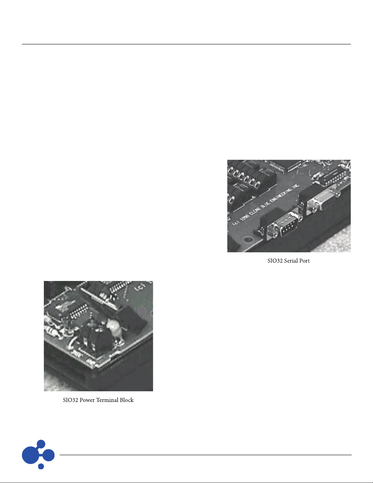
The Input/Output Module (SIO32) is an external RS232 device
that can be congured for both inputs and outputs. The SIO32
module connects to a serial port on the computer. Up to 8 SIO32s
can be aached to each of 8 serial ports, giving users a potenal
of 2,048 input/output opons.
Remove the housing cover of the SIO32 by removing the two
screws from the top of the unit (screws are diagonal with respect
to each other). Inserts in the cover can be removed from the
Output and the Input end of the board to permit wiring to the
terminals. Using the alternate diagonal holes, mount the SIO32
on a at surface using the screws, washers, and anchors supplied
with the unit. Be sure not to over ghten.
The SIO32 connects to the PC serial port using a standard serial cable
that has a DB9 female connector on one end (which is aached to the
SIO32 input marked “IN”), and a DB25 or DB9 male connector on the
other (which is aached to the PC). If this unit is to be daisy chained
(using the same serial port as a previous SIO32), a DB9 male to DB9
female will be required. Plug the DB9 female end into the previous
units Output connector, and plug the DB9 male end into the new units
Input connector.
The SIO32 requires a 9 to 35VDC, 700mA power supply if any Outputs
are to be used. If only Inputs are used, a power supply that supplies
300mA is acceptable. Connect power source Ground to the SIO32
terminal marked GND. Connect the Posive side of the power source to
the terminal marked 9VDC. When power is applied, the PWR LED should
light. If this does not occur, remove power and verify the connecon.
The receiver can be placed up to 25 feet from the PC. For greater
distances, serial line drivers can be used.

15
PALS Installaon Manual
(continued)
The SIO32 Output secon has 32 Form C relays, with connecons arrayed in four rows of terminal blocks with N/O,
N/C, and common terminals for each output.
The SIO32 Input secon consists of two 32-posion terminal strips with inputs on one side and ground terminals
for each posion on the other (ground terminals are on the inside)
Conguraon of the board is accomplished by seng the 8-posion DIP switch.
Posions 1-4 set Input or Output opons for the SIO32, in banks of 8. If switches are in the “O” posion, respecve
points are designated as Outputs. “On” sets them as Inputs.
The same bank cannot be used for both Inputs and Outputs.
The next 3 posions (5 - 7) set the board ID, from 1 to 8. The associated ID is binary based plus 1 (000=1, 001=2,
010=3, 011=4, 100=5, 101=6, 110=7 and 111=8). Boards aached to the same serial port must have dierent IDs.
Any me DIP switches are changed, the Reset buon must be pressed (located next to
the DIP switches), or power to the SIO32 must be removed and reapplied.

16
PALS Installaon Manual
(continued)
ITo program the SIO32, see the Actall® User Manual. Programming idenes the module to the controller, and
enables and integrates its funcon with the system. Outputs can be programmed to toggle states upon acvaon,
or can be set to trip for dened momentary acvaon periods.
The Crisis Controller©™ soware treats SIO32 Inputs like transmiers. They are dened as N/O or N/C (inputs
controlled by switches are always pulled high). Switch transions must be at least 25msec in duraon. This permits
“de-bouncing” of switches. Inputs can be tripped either by switch closure or by voltage changes. In addion,
switches can be programmed to directly trip outputs.
The Crisis Controller©™ can automacally respond to alarm or trouble events by automacally communicang
with on-site or o-site pagers. Users can also manually acvate specic pagers as needed (see Actall® User Manual
for addional details).
The system accommodates mulple pager services, with service to all types of pagers. When programmed or
manually instructed to send a page, the system calls the pager service assigned to the pager and relays numeric or
alphanumeric informaon. This paging interface requires a connecon via a COM port.
Due to the versality of the many paging systems available, please see the manufacturer’s
documentaon for hardware installaon and programming.
The Crisis Controller©™ will support a dedicated line printer that will produce real me printouts of system acvity,
or can be used with a standard printer with reports being requested by Operators or Supervisors.
Aach the printer to the parallel port of the PC using a standard parallel printer cable. With one
end aached to the printer, aach the other end to the Alert Monitoring Hardware Key.
Transmiers should not be mounted on-site unl they have been programmed and labeled for easy idencaon
in the eld. Transmiers are programmed from the Alert Monitoring Center using a programming cable connected
to the Serial Receiver

17
PALS Installaon Manual
(continued)
Baeries must be installed in transmiers before programming. Specicaons and related
programming instrucons for each type of transmier are included in the literature packed with the unit.
The Crisis Controller©™ permits users to test signal strength of individual transmiers that can send signals directly
to the Serial Receiver without the use of a Repeater. If Repeaters are used, either a Survey Kit is required (available
through Actall® Corp.) or the Crisis Controller©™ soware must be installed on a portable machine allowing for
mobility. Please contact Actall® Technical Support for more informaon.
RF signals change with the environment, so signal strength measurements cannot be
relied on solely. Complete supervision of the transmiers and frequent tesng should
be the main course of acon to ensure a working system.
The Crisis Controller©™ soware is oen used in applicaons involving mobile transmiers carried for personal
protecon, by guards or watchmen. In these applicaons, it is extremely valuable to have a system that not only
responds to alarms, but can also provide informaon on the locaon of the personnel carrying the transmiers.
The Crisis Controller©™ has several answers to this challenge.
IRT Locators are special infrared transming devices that generate
an ID code and are received by the PALS©® 9000 Personal Mobile
Transmiers (PMTs). IRT Locators transmit idencaon codes to
PMTs carried by authorized personnel.
The ID code is used to idenfy the alarm locaon or zone from
which the alarm originated. Locaon informaon is subsequently
encoded into the transmissions from the PMT to the PALS©® Alert
Monitoring Center. It is then possible to monitor posion and
movement of the individuals on-site.
IRT Locators connuously transmit locator data code via infrared
light. The PMT includes an infrared receiver that is acvated at
regular intervals. If the PMT is within the coverage area of a Locator,
infrared data is read and stored in the PMT, then included in status
transmissions to the PALS©® Alert Monitoring Center.

18
PALS Installaon Manual
(continued)
IRT devices may be single units, or can consist of combinaons of Master Locators
(IRT-M) ed to a number of Slave Locators (IRT-S), all of which transmit the same
data and create a single zone to provide saturaon coverage of an area.
The reliability of a Locator depends upon the capacity of the alarm transmier
receiving data in a given area. Infrared signals have some transmission limitaons
that can be overcome by careful placement and use of Master-Slave
combinaons.
IRT Locators (Master and Slave) require 12VDC (300mA) power supplies and can
be interconnected with 24-gauge wire in 4-conductor cable.
Use the PALS©® IRT 60703 Tester to program. Detailed instrucons on the use of the
60703 are included with that device.
Posions are 12VDC, Ground (IRT Master power), and Ground and Slave power
(for powering Slave units.) Master IRTs have a red power-on LED indicator. Slave IRTs have a power-on LED as well
as an LED to indicate proper connecon with a Master IRT. Slave IRTs require individual power sources. A single
power source can operate a Master and up to 5 Slaves, if power supply is adequate. Master and Slave Locators
should be connected with 3-conductor 24 to 22-gauge wire. Total combined wire run between Master and Slaves
should not exceed 400 feet.
Determines a “high”, “lower,” and “lowest” power seng for IRT range. With the jumper
in the “HI” posion, the unit operates at 100% power. With the jumper in the “LO” posion, the unit operates at
approximately 60% power. With the jumper “O,” the unit operates at approximately 30% power. Power selecon
is used to reduce range to prevent adjacent IRT zones from overlapping, creang null transmission areas.
Most infrared lenses will reduce the
signal by 3 to 7%. The opmum lens for the IRT-M and
the IRT-S is no lens at all. However, as this is not praccal,
it is very important to use only lenses specied (and
included) by Actall® Corp.
Programming IRTs into Crisis Controller: Aer conguring
and wiring the IRT Master units, IRTs must be programmed
into the Crisis Controller©™ soware. Programming
idenes the IRT to the controller, and enables and
integrates its funcon with the system.
Once IRTs have been programmed in the Crisis
Controller©™, they are accessible to the Guard Route
feature, and can be included in a med and sequenced
patrol path.

PALS Installaon Manual
(continued)
The guiding principle of installing IRT Locators
is that signals to PMTs will be unobstructed and
unambiguous. Wherever IRTs are used, the PMT
must be able to get ONE clear signal at a me. This
means that IRTs must be located in such a way that
users will always be in range of a PMT and that
signals from one IRT can always reach the PMT.
Several factors must be considered. First is range;
the eecve transmission range of an IRT is a
funcon of its total peak output power. IRTs have
jumpers that permit users to use a low power
output, which reduces range. This is somemes
desirable as a means of liming overlapping elds
of coverage between adjacent receivers.
The next factor is locaon of the IRT device. Users typically carry PMTs on belts or service holsters. Signals to the
PMT can be shielded, or “shaded,” by the user’s body if the PMT is worn on the side of the user opposite the
locaon of the IRT. This situaon is addressed by using sets of IRTs. IRT Slaves may be operated in conjuncon with
IRT Masters. They transmit the same locaon data as the Master, at 5%-10% lower power. Strategically
placing these devices in an area guarantees that Locator signals can reach a PMT regardless of where the wearer is
carrying the PMT, or which direcon the user is traveling. (If users must wear heavy protecve gear, use of a Lapel
Reader with the PMT is
recommended.)
IRTs transmit data in 3-dimensions. Coverage may be envisioned as a “cloud” of signals through which the PMT
must pass. IRT signals disperse from their source, and are oen augmented by signal reecon from most materials.
(Carpets and black surfaces are poor reectors).
Installers should place IRTs to eliminate overlapping zones of dual coverage. When signals from adjacent IRTs
collide, “dead zones” are created, from which no viable informaon is accessible to the PMT.
IRTs are not aected by exposure to sunlight,
but PMT receivers can be saturated with
environmental IR and cannot read the Locators.
In these cases, installers should locate the IRTs in
areas that the PMT will not be in direct sunlight
when the Locator data needs to be received.

PALS Installaon Manual
(continued)
IRT range can be reduced by proximity to uorescent lighng. Generally speaking, loss
is minimal if the IRTs are farther than 2 meters from the light source and the light
source is not generang in-band noise. In-band noise is typically generated by
an electronic ballast. IRTs must be mounted per the diagrams shown. Incorrectly
mounng the IRTs may signicantly reduce the range or inhibit the operaon of the
unit. The following are four examples of incorrectly mounted IRTs.
Another method of determining locaon of PMTs is through Wireless RF Locators. These devices are 900MHz
transceivers that aach data to transmier messages indicang which Locator device was the rst to pick up a signal
directly from the transmier. Wireless RF Locators are typically used to provide approximate originaon signals
from PMTs. Wireless RF Locators provide relavely coarse indicaons of locaon, partly due to their extensive
range. They are parcularly well suited for outdoor zoning with the PALS©® transmiers.
Wireless RF Locators can be used very eecvely in conjuncon with IRT Locators. For example, IRT Locators can be
used to closely monitor movement inside a building. They can be programmed to indicate when personnel enter or
leave an IRT-supervised area. If personnel need to move between buildings, for example, RF Locators can provide
larger area coverage while they are in transit. When they enter another building, IRT sensors will note their arrival.
Other manuals for PALS 9K
1
Table of contents


