Issue 3.00
Overview
The NMEA 0183 specication from version 2.0 onwards
requires an RS422 style “differential” connection. The input of
a Listener should be electrically isolated to protect equipment
and wiring against the risk of ground loop damage which is
common in a marine environment. On a standard PC the RS232
input is not isolated and is not differential. The OPTO-4 allows a
differential NMEA 0183 device to correctly connect to a PC and
provide electrical isolation between them.
Powering the OPTO-4
The OPTO-4 takes power from the RS232 TX line and the
handshaking lines RTS and DTR. In most installations especially
when connecting to a PC, no external power supply is required.
In systems that cannot provide power on the handshaking lines,
a DC power supply can be used instead. In this instance use a
male 9-pin D-type connector to connect to the OPTO-4 pins.
For the majority of installations that require external power, only
positive power is needed.
- Connect positive power (9V to 15V) to pin 7
- Connect the power ground to pin 5
- Connect the power ground to pin 4
For some installations both positive and negative supplies may
be required.
- Connect positive power (9V to 15V) to pin 7
- Connect the power ground to pin 5
- Connect negative power (9V to 15V) to pin 4
Note that connecting an external power supply may create a
ground loop between the RS232 device and the power supply.
Ensure that the supply ground is at the same potential as the
RS232 device ground before connecting.
Connecting to a PC
The OPTO-4 has a female 9-pin D-type connector for connect-
ing to a standard RS232 PC serial port, by simply plugging the
OPTO-4 into the serial port of the PC.
Connecting a Talker to the PC
For NMEA 0183 version 2.0 or later:
- Connect the OPTO-4 Red wire to the NMEA 0183
Talker A/+.
- Connect the OPTO-4 Black wire to the NMEA 0183
Talker B/-.
For RS422 or RS485 type devices that are not
specically NMEA 0183, connect as above.
For RS232 devices, whether NMEA 0183 or not:
- Connect the OPTO-4 Red wire to the Talker RS232
Tx or +ve data.
- Connect the OPTO-4 Black wire to the Talker
ground.
Connecting a Listener to the PC
For NMEA 0183 version 2.0 or later (Listener must have an
isolated input):
- Connect the OPTO-4 White wire to the Listener
A/+.
- Connect the OPTO-4 Blue wire to the Listener B/-.
Listeners that use ground for the –ve data line, such as RS232
or older NMEA 0183 V1 devices, the OPTO-4 may not be suita-
ble. There is no isolation between the RS232 port and the Blue
wire.
Connecting the Blue wire to the ground of the Listener will be
connecting it to the ground of the PC. Connecting the OPTO-4
Blue and Black wires together will negate the OPTO-4 isolation.
Connecting to an RS232 Port (non PC)
The connections and power options are the same when con-
necting to a standard RS232, 9-pin D-type connector. Refer to
the sections regarding
connecting to a PC.
Connecting a Serial to USB Converter Cable
Connecting to a USB to Serial converter cable is the same as
connecting to a standard RS232 PC serial port. See section
‘Connectiong to a PC’ replacing all instances of PC with the
converter cable. Note that not all converter cables will provide
power on the handshaking lines, see ‘Powering the OPTO-4’.
Installation Guide
This guide provides the most important information for the
OPTO-4 and its installation.
Actisense recommends users visit the OPTO-4 product page,
www.actisense.com/OPTO-4 for the latest user manual, software
and resources.
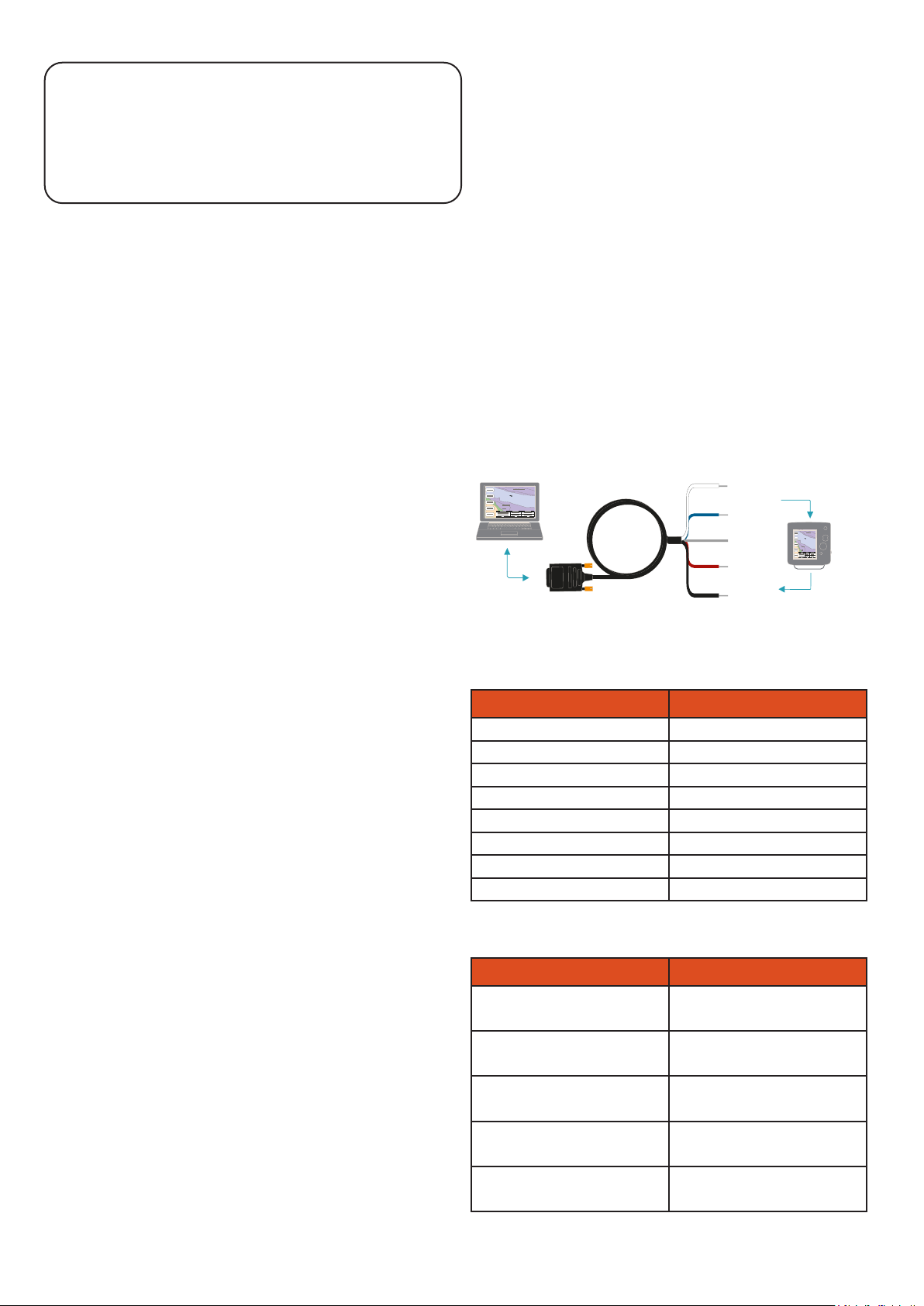
Connection Diagram
RS232 PC Ground
RS232 PC Tx
Cable Shield
NMEA Listener A/+
NMEA Listener B/-
*White Wire
*Blue Wire
*Bare Wire
*Red Wire
*Black Wire
DB9 Pin Out Table
DB9 Pin Number Function
Pin 1 No Connection
Pin 2 PC Rx / OPTO-4 Tx
Pin 3 PC Tx / OPTO-4 Rx
Pin 4 PC DTR / OPTO-4 Power
Pin 5 GND
Pin 6 No Connection
Pin 7 PC RTS / OPTO-4 Power
Pin 8 No Connection
NMEA 0183 Wiring Diagram
OPTO-4 Wire Colour Function (connects to)
Red OPTO-4 Listener Rx A/+
(Talker Tx A/+ or Data)
Black OPTO-4 Listener Rx B/-
(Talker Tx B/- or Ground)
Bare Shield
White OPTO-4 Talker Tx A/+
(Listener Rx A/+ or Data)
Blue OPTO-4 Talker Tx B/-
(Listener Rx B/-)


