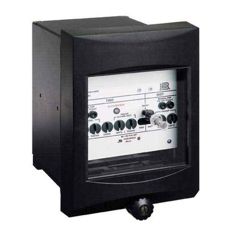
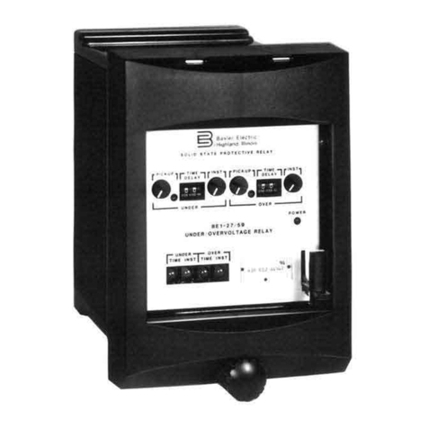
Basler BE-51/27C User manual

!"#$%&'$!(")*+"&+,
-(%
$!*.)(/.%'&%%."$)%.,+0
1!$2)/(,$+3.)'("$%(,
*(4.,)5.67869:;'
<=>?@ABC@DEF G)6H;:)II)GGJ
%KL@M@DEF "DEK

i
W A R N I N G !
To avoid personal injury or equipment damage, only
qualified personnel should perform the procedures
presented in this manual.
!"#$%&'(#!%"
This Instruction Manual provides information concerning the operation and
installation of BE1-51/27C Time Overcurrent (with voltage control) Relays.
To accomplish this, the following is provided.
!Specifications
!Functional characteristics
!Installation
!Operational Tests
!Setting Examples
Service Manual, publication 9 1372 00 620, is available on special order
as an aid in troubleshooting and repair.
REV
ECA

ii
CONFIDENTIAL INFORMATION
OF BASLER ELECTRIC COMPANY, HIGHLAND, IL. IT IS LOANED FOR
CONFIDENTIAL USE, SUBJECT TO RETURN ON REQUEST, AND WITH THE
MUTUAL UNDERSTANDING THAT IT WILL NOT BE USED IN ANY MANNER
DETRIMENTAL TO THE INTEREST OF BASLER ELECTRIC COMPANY.
First Printing: September 1993
Printed in USA
It is not the intention of this manual to cover all details and variations
in equipment, nor does this manual provide data for every possible
contingency regarding installation or operation. The availability and
design of all features and options are subject to modification without
notice. Should further information be required, contact Basler
Electric Company, Highland, Illinois.
BASLER ELECTRIC, BOX 269 HIGHLAND, IL 62249 USA
PHONE 618-654-2341 FAX 618-654-2351

iii
(%"#)"#*
Section 1 GENERAL INFORMATION 1-1
Description ............................................. 1-1
Standard Features ....................................... 1-2
Time Overcurrent ..................................... 1-2
Non-Integrating Timing ................................. 1-3
Integrating Timing ..................................... 1-3
Built-in Test .......................................... 1-3
Options ................................................ 1-3
Timing ............................................. 1-3
Sensing Input Type .................................... 1-3
Sensing Input Range .................................. 1-4
Power Supply ........................................ 1-4
Targets ............................................. 1-4
Outputs ............................................. 1-4
Instantaneous Outputs ................................. 1-5
Packaging ........................................... 1-5
Model and Style Number Description ......................... 1-5
Style Number Identification Chart ............................ 1-6
Specifications ........................................... 1-6
Time Overcurrent Characteristic Curves ....................... 1-9
Section 2 CONTROLS AND INDICATORS 2-1
Section 3 FUNCTIONAL DESCRIPTION 3-1
General ................................................ 3-1
Block Diagram Analysis .................................... 3-1
Power Supply ........................................ 3-1
Current Sensing ...................................... 3-1
Voltage Sensing ...................................... 3-3
Multiplexor .......................................... 3-3
Analog-To-Digital Converter and Level Detector ............. 3-3
Time Trip Comparator and Scaler ......................... 3-3
Microprocessor ....................................... 3-3
Voltage Inhibit ........................................ 3-4
Instantaneous Overcurrent .............................. 3-4
Timed and Instantaneous Outputs ........................ 3-4
Auxiliary Outputs ...................................... 3-4
Push-to-Energize Pushbuttons ........................... 3-4
Power Supply Status Output ............................. 3-4
Target Indicator Circuits ................................ 3-4
Internally Operated Targets ............................. 3-5
Current Operated Targets ............................... 3-5
Section 4 INSTALLATION 4-1
General ................................................ 4-1
Relay Operating Precautions ............................... 4-1

iv
!"#$%#$&'('!)*+,*-./
Section 4 INSTALLATION - Continued
Dielectric Test ........................................... 4-1
Mounting ............................................... 4-1
Connections ............................................ 4-1
Power Supply Type S Input Selection ......................... 4-6
Setting The Relay ........................................ 4-13
General ............................................. 4-13
Setting Example ...................................... 4-13
Coordination With Feeder 51 Relay For Fault 1 .............. 4-15
Checking Coordination With 67 Relay For Fault 2 ............ 4-15
Checking Coordination With 67 Relay For Fault 3 ............ 4-16
Neutral Element Backup Settings ......................... 4-17
Section 5 TESTS AND ADJUSTMENTS 5-1
General ................................................ 5-1
Required Test Equipment .................................. 5-1
Operational Test ......................................... 5-1
Preliminary Instructions ................................. 5-1
Time Overcurrent Pickup Test ........................... 5-5
Timed Output Test .................................... 5-7
Instantaneous Overcurrent Pickup Test .................... 5-9
Voltage Control Test ................................... 5-11
Adjustment of Controls For Relay Operation .................... 5-11
Tap and Tap (Neutral) Selector Setting .................... 5-12
Time Overcurrent Curve Selection (Timing Type Z1, Z2, and Z3) 5-13
Time Delay Selection .................................. 5-14
Neutral Time Delay Selection ............................ 5-14
VOLTS INHIBIT ADJ or VOLTAGE INHIBIT ADJ Setting ....... 5-15
Inst 1 Control Setting .................................. 5-15
Inst 2 Control Setting .................................. 5-16
Section 6 MAINTENANCE 6-1
General ................................................ 6-1
In-House Repair ......................................... 6-1
Storage ................................................ 6-1
Test Plug ............................................... 6-2

1-1
!"#$%&'()
GENERAL INFORMATION
DESCRIPTION
BE1-51/27C Time Overcurrent Relays are microprocessor-based devices that monitor the magnitude of line
current to provide accurate time-overcurrent protection with undervoltage control (when the voltage drops
below the set point, the timing circuit is enabled). Instantaneous overcurrent element(s) and the neutral time
overcurrent element, when supplied, operate independently of the undervoltage function. Each relay is
available with one, three, or four time overcurrent elements.
Basler BE1-51/27C relays provide backup protection for generators or transformers. Voltage control
provides discrimination between load and fault conditions by allowing the time overcurrent pickup to be set
below the maximum load (or swing) current. For sustained fault conditions, the synchronous reactance,
Xd(unsat), is typically larger than for normal load, Xd(sat). As a result, if the regulator is not in service, the three-
phase fault current will be less than the normal maximum load current. The relay pickup should be set below
rated maximum load current (e.g., 50 percent of rated) to ensure dependable backup. The BE1-51/27C
relay may also be used to provide primary phase fault protection for small generators or backup protection
for transformers.
When the BE1-51/27C is used to protect for faults on either side of a delta-wye power transformer, phase
overcurrent units should be supplied on all three phases (either three single-phase relays or one three-phase
relay). For this application, each phase time overcurrent element should be controlled by the phase-to-
ground voltage on its phase, rather than by the phase-phase voltage.
Because the time overcurrent pickup of the phase element(s) does not vary with voltage level (the element
is either enabled or not, depending upon voltage level), conventional time coordination techniques apply.
A neutral (ground) overcurrent element can be applied and connected residually to a set of three current
transformers on solidly grounded applications or on impedance grounded systems that provide ground fault
current approximating the generator rated current level. The neutral element can also be connected to a
10:1 ampere, zero-sequence window current transformer to provide protection on systems producing a
minimum of about 20 amperes primary current. Still another alternative would be connecting this device to
a current transformer in the neutral of a generator or power transformer.
Instantaneous elements can be used for transformer back-up applications when connected on the source
side of the power transformer. Because the pickup of these elements can be set above the relay current
flowing in the low-side fault, coordination can be achieved. Instantaneous overcurrent elements would not
ordinarily be used for a generator back-up function, because they would not operate correctly for faults
external to the generator zone.
Under normal operating conditions, the phase time overcurrent pickup will be less than the maximum load
or non-fault current. As long as the rated voltage is applied to the relay, no operation will occur. However,
if a fuse opens on the voltage transformer and interrupts the signal, the relay will see this as a fault condition
(i.e., current level above pickup and voltage level below minimum set point) and operate accordingly. The
Basler Electric BE1-60 Voltage Balance relay can prevent such a misoperation where two sources of signal
voltage are available. This relay compares the output of two signal sources, to detect an anomaly in one
of these sources and block the operation of those devices connected to that signal source. Therefore, for
generator applications, the Basler BE1-60 Voltage Balance relay should be used in conjunction with the
BE1-51/27C to prevent misoperations due to loss of the voltage source.
BE1-51/27C General Information
1-2
STANDARD FEATURES
Time Overcurrent
Time overcurrent elements pick up over a range of 0.1 to 0.8 amperes, 0.3 to 2.4 amperes, 0.5 to 4.0
amperes, 1.5 to 12.0 amperes, 0.1 to 2.4 amperes, or 0.5 to 12.0 amperes and provide an adjustable time
delay that is proportional to the overcurrent. Time delay is initiated when the sensed current exceeds the
pickup point. When the current drops below the pickup point, the timing circuit is reset immediately. At
reset, the output contacts, if operated, are restored to normal.
Adjustment of the overcurrent pickup point is provided by controls on the relay front panel. Time delay is a
function of the characteristic curve that has been selected. Time delay is settable from 00 to 99 on the front
panel Time DIAL thumbwheel switch. Curve type is either selected as an option or, in some models, is
switch selectable.
Sixty-nine characteristic curves and three timing options are available. They are:
Characteristic curves:
!Seven inverse time
!Nine I2T
!Seven inverse time with extended timing range
!Nine I2T with extended timing range
!Five British Standard 142 (E curves)
!Seven integrating inverse time
!Nine integrating I2T
!Seven integrating inverse time with extended timing range
!Nine integrating I2T with extended timing range
Timing option Z1 (switch selectable - 16 position) B & C curves:
!Seven inverse time
!Nine I2T
Timing option Z1 with option 2-D or 2-E, (switch selectable - 16 position) B and C curves:
!Seven inverse time with extended timing range
!Nine I2T with extended timing range
Timing option Z2 (switch selectable - 16 position) B and E (British Standard 142) curves:
!Seven inverse time
!One I2T
!Five British Standard (BS) 142 (E curves)
Timing option Z2 with option 2-D or 2-E, (switch selectable - 16 position) B and E (BS142) curves:
!Seven inverse time with extended timing range
!One I2T with extended timing range
!Five British Standard 142 (E curves)
Timing option Z3 (switch selectable - 16 position) integrating B & C curves:
!Seven integrating inverse time
!Nine integrating I2T

BE1-51/27C General Information
1-3
Timing option Z3 with option 2-D or 2-E, (switch selectable - 16 position) integrating extended B &
C curves:
!Seven integrating inverse time with extended timing range
!Nine integrating I2T with extended timing range
Characteristic curves are shown by the graphs in Figures 1-2 through 1-70. Note that each graph (i.e.
function) consists of a set of representative curves. Each curve (as well as any between-curve interpolation)
is selectable by the front panel TIME DIAL using a two-digit designation from 00 to 99. Because of space
limitations, each graph shows only 14 of the 100 possible selections.
Non-Integrating Timing
Timing options Z1 and Z2 and the characteristic curves available with those options use non-integrating
timing. Non-integrating timing is accomplished by timing at a gate that is not solely dependent on the
magnitude of the applied multiple of pickup current. The time-out value is calculated based on the type of
time curve characteristic selected, time dial setting, and the magnitude of the applied multiple of pickup
current. The time-out value is continuously updated during the timing cycle. When pickup is exceeded, a
timer is initiated. When the timer elapsed time exceeds the calculated time-out value, a time trip output
signal is generated.
This type of non-integrating time delay characteristic exhibits a dynamic characteristic that is immediately
responsive to changes of the applied multiple of pickup current.
Integrating Timing
Timing option Z3 and the characteristic curves available for that option uses integrating timing. Integrating
timing is accomplished by summing time increments that are based on the magnitude of the applied multiple
of pickup current, the time curve characteristic selected, and the time dial value. These time increments are
summed until a predetermined value is exceeded, then a time trip output signal is generated.
This type of integrating time delay characteristic simulates the operating characteristics of an
electromechanical overcurrent relay.
Built-In Test
A built-in test (BIT) switch mounted on the Logic Board provides diagnostic troubleshooting and calibration
in conjunction with the procedures provided in Service Manual, publication 9 1372 00 620.
OPTIONS
Timing
An extended timing option multiplies by approximately 5.7, the standard time delays. The resulting curves
are shown following the standard curves—e.g., Figure 1-2 is timing type B1 and Figure 1-3 is the timing type
B1 with extended timing range.
When timing option Z1, Z2, or Z3 is specified, a printed circuit board mounted selector switch allows a choice
of up to sixteen different time overcurrent functions. Timing option Z1 or Z3 may be further specified as stan-
dard or extended time, depending upon option 2 selection.
Sensing Input Type
When single-phase, two-phase-and-neutral, three-phase, or three-phase-and-neutral sensing has been

BE1-51/27C General Information
1-4
specified, the front panel TAP selector and the front panel TAP CAL control set the pickup point for all
phases. An independent front panel TAP (NEUTRAL) selector and front panel CAL (NEUTRAL) control
set the neutral pickup point. Also, for three-phase-and-neutral sensing units, one of the seven sensing input
range combinations must be specified.
Relay circuits inhibit the phase-element time overcurrent operation for a specific phase if the monitored ac
voltage exceeds a preselected level. The voltage level is established by a front panel VOLTS ADJ control
and all phases are inhibited at the same voltage level.
Neutral overcurrent elements are not inhibited
. When
the voltage inhibit level is exceeded, front panel INHIBIT LED is lit for the affected phase, and the front panel
TIMING LED for that particular phase extinguishes.
Sensing Input Range
For three-phase-and-neutral sensing units, input ranges are:
!0.5 to 4.0 amperes (phase and neutral)
!1.5 to 12 amperes (phase) and 0.5 to 4.0 amperes (neutral)
!0.5 to 4 amperes (phase) and 1.5 to 12 amperes (neutral)
!1.5 to 12 amperes (phase and neutral)
!0.1 to 0.8 amperes (phase and neutral)
!0.3 to 2.4 amperes (phase) and 0.1 to 0.8 amperes (neutral)
!0.3 to 2.4 amperes (phase and neutral)
For all other units, two ranges are available. They are 0.5 to 12 amperes and 0.1 to 2.4 amperes.
Power Supply
Five power supply options are available. They are:
!48 Vdc
!125 Vdc and 100/125 Vac
!24 Vdc
!48 Vdc or 125 Vdc and 100/125 Vac (jumper selectable)
!250 Vdc and 230 Vac
Targets
Single-phase relays have two function targets that indicate when the time delay or instantaneous
elements(s) have operated. On multiple phase relays, additional targets indicate which phase or neutral
elements(s) operated.
Function targets may be specified as either internally operated or current operated by a minimum of 0.2
amperes through the output trip circuit. When current operated, the output circuit must be limited to 30
amperes for 0.2 seconds, 7 amperes for 2 minutes, and 3 amperes continuously. Element targets are
internally operated.
Outputs
Optional normally opened, normally closed, or SPDT auxiliary output contacts may be selected. Contacts
actuate when the output relay is energized. Internally operated front panel mounted targets, and front panel
targets operated by the dc current in the output circuit are available for the time overcurrent and
instantaneous overcurrent functions. Optional front panel mounted PUSH-TO-ENERGIZE-OUTPUT
pushbuttons allow direct actuation of each output relay for external circuit testing.

BE1-51/27C General Information
1-5
Instantaneous Outputs
One or two instantaneous overcurrent outputs are optionally available. Each is adjustable up to 40 times
the time overcurrent pickup point. When the sensed current exceeds the instantaneous overcurrent pickup
point, an output relay is energized. An independent front panel control (INST 1 or INST 2) adjusts the pickup
point for each optional output. If more than one phase is applied to the relay, the instantaneous pickup point
will be the same for all phases. If neutral current is sensed, a front panel INST 1 (NEUTRAL) provides
adjustment of the neutral pickup point. Instantaneous overcurrent elements are not voltage controlled.
Packaging
Each relay is mounted in a drawout cradle and enclosed in a standard utility style case with either semi-flush
or projection mounting (depending upon case style selected). Circuit components are accessed by removing
the individual printed circuit boards from the relay cradle. Use an extender card (Basler Electric part number:
9 1655 00 100) to test and troubleshoot the relay. An available test plug (Basler Electric part number: 10095
or G.E. part number 12XLA12A1) allows the relay to be tested in place without disturbing external control
circuit wiring.
MODEL AND STYLE NUMBER DESCRIPTION
BE1-51/27C Time Overcurrent Relays electrical characteristics and operational features are defined by a
combination of letters and numbers that make up its style number. The model number, together with the
style number, describe the options included in a specific device, and appear on the front panel, drawout
cradle, and inside the case assembly. Upon receipt of a relay, be sure to check the style number against
the requisition and the packing list to ensure that they agree.
Style number identification chart (Figure 1-1) defines the electrical characteristics and operational features
included in BE1-51/27C relays. For example, if the style number were T3E Z1P B1C1F, the device would
have the following:
(T) -3-Phase-and-neutralsensing,60Hz.
(3) -Sensinginputrangeof1.5to12.0Aforphase,0.5to4.0Aforneutral.
(E) -N.O.outputs.
(Z1) -SwitchselectableBandCtimeovercurrentcharacteristiccurves.
(P) -Operatingpowerderivedfrom125Vdcor100/120Vac.
(B) -Currentoperatedtargets.
(1) -Oneinstantaneouselement.
(C) -Push-to-energizeoutputs.
(1) -N.O.auxiliarytimedoutputrelay.
(F) -Semi-flushmounting.

BE1-51/27C General Information
1-6
Figure 1-1. Style Number Identification Chart
SPECIFICATIONS
BE1-51/27C Time Overcurrent Relays electrical and physical specifications are as follows:
!"#$%&'()'*+,*&(-*./$+ Rated for 160 Vac continuous at 40 to 70 Hz (nominal frequency 50 or 60
Hz), with a maximum burden of 1 VA.
!"#$%&'()'*+,*&()'#'0$,"* Continuously adjustable over the range of 40 to 120 Vac.
1%*&'
Voltage Sensing Accuracy ±2% of pickup setting.
Sensing Input Burden Less than 0.1 ohms per phase or neutral.

BE1-51/27C General Information
1-7
I
!(50
X tap value or
500
A
,
whichever is less
)
T
Sensing Input Rating The maximum 1 second current rating is 50X (times)
maximum tap current selected, or 500 A, whichever is less. Maximum
continuous current is 20 A. For ratings other than those specified by the
time curves, rating is a calculated as follows:
Where: I = Maximum Current, and T = Current Flow in Seconds
Time Overcurrent Pickup Continuously adjustable over the current sensing input ranges specified
Selection Range in the Style Chart (Figure 1-1).
Time Overcurrent Measuring ±2% of the pickup setting.
Accuracy
Time Overcurrent Dropout Better than 95% of pickup level.
Ratio
Instantaneous Overcurrent Continuously adjustable over the range of 1 to 40 times the time
Pickup Range overcurrent pickup setting.
Instantaneous Overcurrent ±2% of pickup setting.
Measuring Accuracy
Instantaneous Overcurrent Better than 98% of pickup level.
Dropout Ratio
Time Delay Accuracy ±5% of the characteristic curve (Figures 1-2 through 1-70) for any com-
bination of the front panel TIME DIAL setting and the front panel TAP/TAP
CAL overcurrent pickup setting.
Repeatability is within ±2% of setting at 25"C.
Output Circuits Output contacts are rated as follows:
Resistive:
120/240 Vac Make 30 A for 0.2 seconds, carry 7 A continuously, and break 7 A.
250 Vdc Make and carry 30 A for 0.2 seconds, carry 7 A continuously, and break
0.3 A.
500 Vdc Make and carry 15 A for 0.2 seconds, carry 7 A continuously, and break
0.1 A.
Inductive:
120/240 Vac, Make and carry 30 A for 0.2 seconds, carry 7 A continuously, and break
125/250 Vdc 0.3 A. (L/R = 0.04).
Target Indicators Function targets may be specified as either internally operated, or current
operated by a minimum of 0.2 A through the output trip circuit. When cur-
rent operated, the output circuit must be limited to 30 A for 0.2 seconds, 7
A for 2 minutes, and 3 A continuously.

BE1-51/27C General Information
1-8
Power Supply Input power may be obtained from a variety of ac or dc external power
sources. Refer to Table 1-1 for available power supply options
Table 1-1. Power Supply Specifications
Type
Nominal
Input
Voltage
Input
Voltage
Range
Burden
at
Nominal
O48Vdc24to60Vdc6.6W
P125Vdc
120 Vdc
62 to 150 Vdc
90 to 132 Vdc
6.7 W
12.8 W
R24Vdc12to32Vdc7.2W
S * 48 Vdc
125 Vdc
24 to 60 Vdc
62 to 150 Vdc
5.0 W
5.3 W
T250Vdc
230 Vac
140 to 280 Vdc
190 to 270 Vac
7.8 W
19.8 VA
NOTES:
All references are at 50/60 Hz.
*Type S Power Supply is field selectable for 48 or 125 Vdc. Selection
must be implemented at time of installation. This Power Supply option
is factory set for 125 Vdc.
Isolation 1500 Vac at 60 hertz for one minute in accordance with IEC 255-5 and
ANSI/IEEE C37.90-1989 (Dielectric Test).
Radio Frequency Field Tested using a five watt, hand-held transceiver operating at
Interference (RFI) random frequencies centered around 144 MHz and 440 MHz, with the
antenna located six inches from the relay in both horizontal and vertical
planes.
Surge Withstand Capability Qualified to ANSI/IEEE C37.90.1-1989
Standard Surge Withstand Capabil-
ity (SWC) Tests for Protective Relays and Relay Systems.
UL Recognized UL Recognized per Standard 508, UL File No. E97033. Note: Relay is not
UL Recognized for output contact voltages greater than 250 volts and input
power supply voltages greater than 150 volts.
Operating Temperature -40"C (-40"F) to +70"C (+158"F).
Storage Temperature -65"C (-85"F) to +100"C (+212"F).
Shock In standard tests, the relay has withstood 15 g in each of three mutually
perpendicular planes without structural damage or degradation of perfor-
mance.

BE1-51/27C General Information
1-9
Vibration: In standard tests, the relay has withstood 2 g in each of three mutually per-
pendicular planes, swept over the range of 10 to 500 Hz for a total of six
sweeps, 15 minutes each sweep, without structural damage or degradation
of performance.
Weight
Single-Phase:
13.0 lbs. (5.9 kg)
Three-Phase:
14.0 lbs. (6.4 kg)
Three-Phase-and-Neutral:
14.4 lbs. (7.2 kg)
Case Size S1.
TIME OVERCURRENT CHARACTERISTIC CURVES
Graphs on the following pages illustrate sample characteristic curves for all of the time overcurrent functions
individually as options, or selectable by switch (if the Z1, Z2, or Z3 timing option is specified). Z1 option can
select any of the timing types designated as B1 through B8, and C1 through C8. Z2 option can select any
of the timing types designated as B1 through B8, and the British Standard timing types: E2, E4, E5, E6, and
E7. Z3 option can select the integrating algorithm for any of the timing types designated as B1 through B8,
and C1 through C8.
Note that there are two versions of each timing type: standard and extended timing. Both types are located
on the same page. The exception to this is the British Standard curves which do not have an extended
timing version. For any given relay, either the standard or the extended range version will apply, never both.
A drawing number is provided with each characteristic curve chart. Use this number to order the full-size
(11" X 17") characteristic curve chart on transparent paper (vellum). Publication 9 1372 00 897 contains 36
full size characteristic curve charts (timing options Z1 and Z2). To order any of these characteristic curve
charts, contact Customer Service Department of the Power Systems Group, Basler Electric.

2-1
!"#$%&'()
!"#$%"&'()#*(+#*+!)$"%'
GENERAL
Table 2-1 lists and briefly describes the operator controls and indicators of the BE1-51/27C Time
Overcurrent Relay with voltage control. Reference the call-out letters to Figure 2-1.
Table 2-1. Controls and Indicators
Letter Control or Indicator Function or Indicator
ATAP NEUTRAL Selector Provides selection of the neutral overcurrent pickup
point in conjunction with the front panel NEUTRAL
CAL control.
BPHASE - TAP Selector Provides the selection of the overcurrent pickup point
in conjunction with the front panel TAP CAL control.
CCAL NEUTRAL Control (On
Relays with Phase-and-
Neutral Sensing Only)
A single turn potentiometer provides adjustment of the
neutral overcurrent pickup point between the selected
tap setting and the next lower tap setting.
Not
Shown
TAP RANGE Plate High/Low Plate position indicates the terminal connections (high
or low) used to select the current sensing input range.
Refer to Table 2-2 for sensing input ranges.
DTIME DIAL NEUTRAL (If
present)
Determines the time delay between sensing of the
overcurrent condition and the closing of the output
relay. Refer to Section 1 and Table 2-3 for curve
selection information.
ETIMING NEUTRAL (If pres-
ent)
LED illuminates when the neutral pre-set overcurrent
pickup point is reached and exceeded.
FTimeCurrentCharacteristic
Curve Selector (Z1, Z2, and
Z3 Timing Options Only)
Provides selection of the time current characteristic
curves. Refer to Section 1 and Table 2-3 for curve
selection information. Cutaway view shows switch
behind the front panel.
GPOWER Indicator LED illuminates to indicate that the relay power
supply is functioning.
HTargetResetLever Manuallyresetsalltargets(bothelementandfunction
type).
IFUNCTION Targets TIME
INST1, INST2*
Front panel FUNCTION targets trip when the
corresponding output relay is energized by an
overcurrent condition.
JELEMENT Targets Front panel ELEMENT targets trip when an output
relay is energized by an overcurrent condition.

BE1-51/27C Controls and Indicators
2-2
Figure 2-1. Location of Controls and Indicators

BE1-51/27C Controls and Indicators
2-3
Table 2-1. Controls and Indicators - Continued
Letter Control or Indicator Function or Indicator
KPUSH-TO-ENERGIZE OUT-
PUT Pushbutton
Actuation of this function is by a thin non-conducting rod
(
do not use a screwdriver
) through a hole in the front
panel. This allows the output relays to be manually
energized for testing of the external trip circuit(s).
ELEMENT targets, where supplied, are not operated by
this control.
LTIMING Indicator LEDs illuminate when the preset overcurrent pickup point
is reached and exceeded.
MTIME DIAL Selector Determines the time delay between sensing of the
overcurrent condition and the closing of the output relay.
Refer to Section 1 and Table 2-3 for curve selection
information.
NTAP CAL Control A single turn potentiometer provides adjustment of the
phase overcurrent pickup point between the selected tap
setting and the next lower tap setting.
OINST 1 Control (Options 1-1
and 1-2 Only) **
A four turn potentiometer provides adjustment of the front
panel INST 1 trip setting over the range of 1 to 40 times
the selected phase time overcurrent pickup (TAP) value.
PVOLTAGE INHIBIT A, B, C*
ADJ
A four turn potentiometer provides continuous adjustment
over a range of 40 to 120 Vac of the sensed input front
panel VOLTAGE INHIBIT level.
QVOLTAGE INHIBIT A, B, C*
Indicator(s)
LEDs illuminate when the sensed input voltage level
exceeds the front panel pre-set VOLTAGE INHIBIT level.
RINST 1 NEUTRAL Control
(Options 1-1 and 1-2 Only)**
A four turn potentiometer provides adjustment of the front
panel INST 1 NEUTRAL trip setting over the range of 1 to
40 times the selected neutral time overcurrent pickup
(TAP) value.
Not
Shown
INST 2 Control (Option 1-2
Only) **
A four turn potentiometer provides adjustment of the front
panel INST 2 trip setting of the range of 1 to 40 times the
selected phase time overcurrent pickup (TAP) value.
Not
Shown
N/T (Normal/Test) Switch S1 This switch is mounted internally on the logic board.
Switch S1 provides stored built-in-test (BIT) programs
used during troubleshooting, repair, and calibration. This
switch is not used during normal relay setting or
operational testing.
LEGEND
*Thenumberofphasesandneutralsensedbytherelayisdefinedbythesensinginputtype(See
the Style Identification Chart, Figure 1-1).
** This Instantaneous overcurrent sensing circuit detects levels that are multiples of the level
selected for the time overcurrent sensing circuit. Any change of the tap selector or calibration
(CAL) controls will cause a directly proportional change of the instantaneous overcurrent Levels.

BE1-51/27C Controls and Indicators
2-4
Table 2-2. Sensing Input Ranges
TAP Range
Plate or
Pickup
TAP Selector Current Sensing Terminals
AB CD E F GH I J !A!B!CN
Range 1, Single-Phase †
HIGH 2.25 3.00 4.50 5.25 6.75 7.50 9.00 9.75 11.2
5
12.0
0
8,7 ----- ----- -----
LOW 0.75 1.00 1.50 1.75 2.25 2.50 3.00 3.25 3.75 4.00 9,7 ----- ----- -----
Range 1, Three-Phase †
HIGH 2.25 3.00 4.50 5.25 6.75 7.50 9.00 9.75 11.2
5
12.0
0
8,7 14,15 17,18 -----
LOW 0.75 1.00 1.50 1.75 2.25 2.50 3.00 3.25 3.75 4.00 9,7 13,15 16,18 -----
Range 1, Two-Phase-and-Neutral †
HIGH 2.25 3.00 4.50 5.25 6.75 7.50 9.00 9.75 11.2
5
12.0
0
8,7 ----- 14,15 17,18
LOW 0.75 1.00 1.50 1.75 2.25 2.50 3.00 3.25 3.75 4.00 9,7 ----- 13,15 16,18
Range 2, Three-Phase-and-Neutral
Phase or
Neutral 0.75 1.00 1.50 1.75 2.25 2.50 3.00 3.25 3.75 4.00 8,9 13,14 15,16 17,18
Range 3, Three-Phase-and-Neutral
Phase 2.25 3.00 4.50 5.25 6.75 7.50 9.00 9.75 11.2
5
12.0
0
8,9 13,14 15,16 -----
Neutral 0.75 1.00 1.50 1.75 2.25 2.50 3.00 3.25 3.75 4.00 ----- ----- ----- 17,18
Range 4, Three-Phase-and-Neutral
Phase 0.75 1.00 1.50 1.75 2.25 2.50 3.00 3.25 3.75 4.00 8,9 13,14 15,16 -----
Neutral 2.25 3.00 4.50 5.25 6.75 7.50 9.00 9.75 11.2
5
12.0
0
----- ----- ----- 17,18
Range 5, Three-Phase-and-Neutral
Phase
or
Neutral
2.25 3.00 4.50 5.25 6.75 7.50 9.00 9.75 11.2
5
12.0
0
8,9 13,14 15,16 17,18
Range 6, Three-Phase-and-Neutral
Phase
or
Neutral
0.15 0.20 0.30 0.35 0.45 0.50 0.60 0.65 0.75 0.80 8,9 13,14 15,16 17,18
Range 7, Three-Phase-and-Neutral
Phase 0.45 0.60 0.90 1.05 1.35 1.50 1.80 1.95 2.25 2.40 8,9 13,14 15,16 -----
Neutral 0.15 0.20 0.30 0.35 0.45 0.50 0.60 0.65 0.75 0.80 ----- ----- ----- 17,18
Range 8, Three-Phase-and-Neutral
Phase
or
Neutral
0.45 0.60 0.90 1.05 1.35 1.50 1.80 1.95 2.25 2.40 8,9 13,14 15,16 17,18
Range 9 (All Other Sensing Types)
Phase
or
Neutral
0.10 0.15 0.20 0.30 0.40 0.60 0.80 1.20 1.60 2.40 8,9 13,14 15,16 17,18
NOTE: †Forrelayswithsensinginputrange1,connectthesystemwiringtothecurrent
sensing terminals for the desired range (HIGH or LOW).

BE1-51/27C Controls and Indicators
2-5
Table 2-3. Timing Curve Selection Table
Timing Type
Selector
Position
Selector
Position
Standard
Curves
Z1, Z2
Fig. No.
Extended
Curves
Z1, Z2
Fig. No.
Standard
Curves
Z3
Fig. No.
Extended
Curves
Z3
Fig. No.
B1 - Short Inverse 3 3 1-2 1-3 1-39 1-40
B2 - Long Inverse 1 1 1-4 1-5 1-41 1-42
B3 - Definite Time 5 5 1-6 1-7 1-43 1-44
B4 - Moderately
Inverse
221-81-91-451-46
B5 - Inverse 4 4 1-10 1-11 1-47 1-48
B6 - Very Inverse 6 6 1-12 1-13 1-49 1-50
B7 - Extremely Inverse 7 7 1-14 1-15 1-51 1-52
B8 - I2T001-161-171-531-54
C1 - I2T with Limit #1 8 --- 1-18 1-19 1-55 1-56
C2 - I2T with Limit #2 9 --- 1-20 1-21 1-57 1-58
C3 - I2T with Limit #3 A --- 1-22 1-23 1-59 1-60
C4 - I2T with Limit #4 B --- 1-24 1-25 1-61 1-62
C5 - I2T with Limit #5 C --- 1-26 1-27 1-63 1-64
C6 - I2T with Limit #6 D --- 1-28 1-29 1-65 1-66
C7 - I2T with Limit #7 E --- 1-30 1-31 1-67 1-68
C8 - I2T with Limit #8 F --- 1-32 1-33 1-69 1-70
E2 - Long Inverse --- 8 1-34 --- --- ---
E4 - Inverse (1.3 Sec) --- 9 1-35 --- --- ---
E5 - Inverse (3.0 Sec) --- A 1-36 --- --- ---
E6 - Very Inverse --- B 1-37 --- --- ---
E7 - Extremely Inverse --- C,D,E,F 1-38 --- --- ---
NOTES:
†Timing Option Z1 and Z3.
‡Timing Option Z2 only.
Table 2-4. Target Installation Configurations
Sensing
Input
Type
Number of
Instantaneous Elements
Targets Installed
(Types A and B)
None One Two
Element Function
ABCD TIME INST1 INST2
L
XX
X XX
X XXX
P
XXXX
XXXXXX
T
XXXXX
XXXXXXX
A
XXXXXX
XXXX X X
D
XXXXXXX
XXXXXX X
J
XXXXX
XXXXXX

BE1-51/27C Controls and Indicators
2-6
Table of contents
Other Basler Relay manuals

Basler
Basler BE1-59N User manual

Basler
Basler BE1-67N User manual

Basler
Basler BE1-11g User manual

Basler
Basler BE1-59NC User manual

Basler
Basler BE1-49 User manual

Basler
Basler BE1-50B User manual

Basler
Basler BE1-50/51B-218 User manual

Basler
Basler BE1-51/27R User manual

Basler
Basler BE1-27 User manual

Basler
Basler BE1-59NC User manual

Basler
Basler BE1-51M User manual

Basler
Basler BE1-67 User manual

Basler
Basler BE1-50/51B-232 User manual

Basler
Basler BE1-32R User manual

Basler
Basler BE1-79A User manual

Basler
Basler BE1-40Q User manual

Basler
Basler BE1-32R User manual

Basler
Basler BE1-81O/U User manual

Basler
Basler BE1-51/27R User manual

Basler
Basler BE1-27 User manual