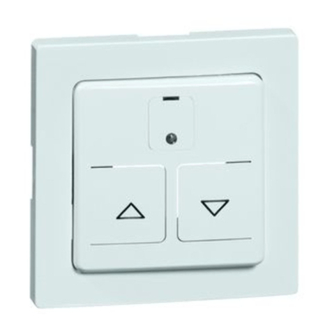
Acuity Controls rPODBA Series User manual

Acuity Brands | One Lithonia Way Conyers, GA 30012 Phone: 800.535.2465 www.acuitybrands.com/nLight © 2019-2021 Acuity Brands Lighting, Inc. All rights reserved. 04/29/2021 1 of 2
912-00087-002
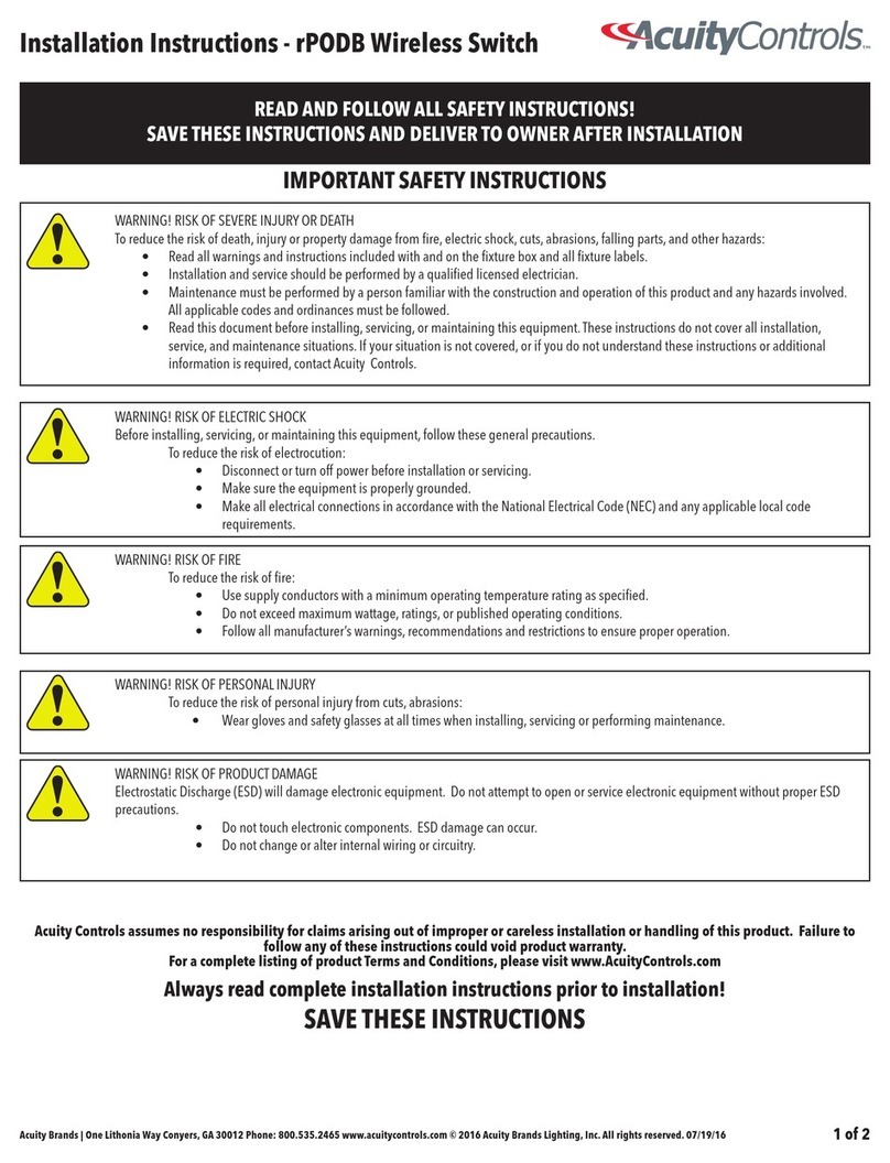
READ AND FOLLOW ALL SAFETY INSTRUCTIONS!
SAVE THESE INSTRUCTIONS AND DELIVER TO OWNER AFTER INSTALLATION
Installation Instructions - rPODBA Wireless Switch
IMPORTANT SAFETY INSTRUCTIONS
Always read complete installation instructions prior to installation!
SAVE THESE INSTRUCTIONS
WARNING! RISK OF SEVERE INJURY OR DEATH
To reduce the risk of death, injury or property damage from fire, electric shock, cuts, abrasions, falling parts, and other hazards:
• Read all warnings and instructions included with and on the fixture box and all fixture labels.
• Installation and service should be performed by a qualified licensed electrician.
• Maintenance must be performed by a person familiar with the construction and operation of this product and any hazards involved.
All applicable codes and ordinances must be followed.
• Read this document before installing, servicing, or maintaining this equipment.These instructions do not cover all installation,
service, and maintenance situations. If your situation is not covered, or if you do not understand these instructions or additional
information is required, contact Acuity Controls.
WARNING! RISK OF ELECTRIC SHOCK
Before installing, servicing, or maintaining this equipment, follow these general precautions.
To reduce the risk of electrocution:
• Disconnect or turn off power before installation or servicing.
• Make sure the equipment is properly grounded.
• Make all electrical connections in accordance with the National Electrical Code (NEC) and any applicable local code
requirements.
WARNING! RISK OF FIRE
To reduce the risk of fire:
• Use supply conductors with a minimum operating temperature rating as specified.
• Do not exceed maximum wattage, ratings, or published operating conditions.
• Follow all manufacturer’s warnings, recommendations and restrictions to ensure proper operation.
WARNING! RISK OF PERSONAL INJURY
To reduce the risk of personal injury from cuts, abrasions:
• Wear gloves and safety glasses at all times when installing, servicing or performing maintenance.
WARNING! RISK OF PRODUCT DAMAGE
Electrostatic Discharge (ESD) will damage electronic equipment. Do not attempt to open or service electronic equipment without proper ESD
precautions.
• Do not touch electronic components. ESD damage can occur.
• Do not change or alter internal wiring or circuitry.
!
!
!
!
!
Acuity Controls assumes no responsibility for claims arising out of improper or careless installation or handling of this product. Failure to
follow any of these instructions could void product warranty.
For a complete listing of product Terms and Conditions, please visit www.AcuityControls.com
NOTE: This equipment has been tested and found to comply with the limits for a Class B digital device, pursuant to part 15 of the FCC Rules. These limits are designed to provide reasonable protection against harmful interference in a
residential installation. This equipment generates, uses and can radiate radio frequency energy and, if not installed and used in accordance with the instructions, may cause harmful interference to radio communications. However, there is no
guarantee that interference will not occur in a particular installation. If this equipment does cause harmful interference to radio or television reception, which can be determined by turning the equipment off and on, the user is encouraged
to try to correct the interference by one or more of the following measures:
1. Reorient or relocate the receiving antenna.
2. Increase the separation between the equipment and receiver.
3. Connect the equipment into an outlet on a circuit different from that to which the receiver is connected.
4. Consult the dealer or an experienced radio/TV technician for help.
This device complies with Part 15 of the FCC Rules. Operation is subject to the following two conditions: (1) This device may not cause harmful interference, and (2) this device must accept any interference
received, including interference that may cause undesired operation.
La operación de este equipo está sujeta a las siguientes dos condiciones: (1) es posible que este equipo o dispositivo no cause interferencia perjudicial y (2) este equipo o dispositivo debe aceptar cualquier
interferencia, incluyendo la que pueda causar su operación no deseada.
Contains FCC ID: 2ADCB-RMODIT or 2ADCB-RMODIT3
Contains IC: 6715C-RMODIT or 6715C-RMODIT3
IFT #: RCPACRM18-1879 or RCPNLNL20-2057
Acuity Brands Lighting Inc. RMODIT or RMODIT3

Acuity Brands | One Lithonia Way Conyers, GA 30012 Phone: 800.535.2465 www.acuitybrands.com/nLight © 2019-2021 Acuity Brands Lighting, Inc. All rights reserved. 04/29/2021 2 of 2
912-00087-002
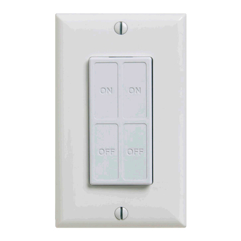
The rPODBA is a wireless switch that can be interconnected with the nLight® AIR network of wireless
sensors and switches.
rPODBA Basic Overview
Mounting Instructions/Important Notes
INSTALLATION:
Installation of the rPODBA wall switch is simple, straight forward, and quick! Designed as truly “wire-free” with embedded wireless and battery power, installation requires zero wiring. Follow the simple
steps below to perform the mechanical installation of the rPODBA Wall Switch.
OUT-OF-THE-BOX DECORA WALL PLATE:
OUT-OF-THE-BOX DECORA WALL PLATE:
When installing the unit with standard off-the-shelf decora wall plates, the following steps should be followed.
• Remove the wall plate from the device by pulling the sides out to expand the wall plate and release it from the mounting flanges.
• Connect the unit to the gang box
o The unit will connect to the gang box by screws, one at the top and one at the bottom
o To ensure correct wall plate installation, drive the screws until the mounting flanges contact the wall surface. If the screws are overdriven, the mounting flanges will
disengage, preventing wall plate installation. If this happens, reattach the mounting flange(s) and install to correct position. (The flanges may be reattached by
inserting the two tabs in the side of the unit and pushing the part inward to engage the three snaps.)
• Reattach the wall plate
o Expand the wall plate horizontally
o Place the wall plate onto the unit
o Contract the horizontally expanded wall plate onto the unit such that the side flange features seat inside the wall plate
• No wiring needed
• Remove the Acuity wall plate from the device by pulling the sides out to expand the wall plate and releasing it from the mounting flanges.
• Unhook and remove the side flanges from the device
• Connect the unit to the gang box
o The unit will connect to the gang box by screws, one at the top and one at the bottom
• Attach the wall plate
Installation Instructions - rPODBA Wireless Switch
BATTERY REPLACEMENT:
• Remove wall plate.
• Carefully pry the retainer clip away from the module while pulling the rPODBA from the retainer housing.
o Using a flat head screwdriver, carefully pry the retainer clip away from the module. Use the tip of the screwdriver to pry
against the tab on the module to help remove the rPODBA module from the retainer clip. Otherwise, simply unscrew the
retainer and module together from the gang box, then separate the module from the retainer.
• Remove the battery cover with a short slide of the door, then lift battery cover off.
o Note the arrow on the battery cover for direction to slide cover, also the ridges on the side for finger grips.
• Remove old batteries and replace with new ones.
• Reinstall battery cover by aligning the battery cover line with the line on the on the module, then slide shut.
• Reinstall the rPODBA Module into the retainer until secured
• Reinstall wall plate
• Done!
DEVICE PROGRAMMING:
• Add rPODBA to the appropriate nLight Air group and control zone(s) using the Clairity Pro mobile app. Upon successfully saving, the switch will automatical-
ly control the lights in the space.
For preset scene capable switches only (i.e. “2S” and “4S” devices):
• After assigning to the nLight Air group, preset scenes buttons will automatically operate under the following default settings:
Holding the button for greater than 10 seconds will bring the
switch into a wake-up mode (identified by all LEDs lit solid), and
updated preset scene will not save.
• The preset scene levels can be changed by first adjusting the light level of the nLight Air devices in the group with either the unit’s raise/lower buttons (i.e. rPODBA 2S DX, rPODBA 4S DX), via
additional on/off/raise/lower rPODBA in the group, or through SensorView if the nLight Air group is networked.All devices in the nLight Air group (i.e. nLight Air enabled fixtures, power packs) can
be set to the same or different levels, and ALL devices in the group must be included in the preset scene (i.e. devices must be set to off, or a level between 1 – 100%, and cannot be excluded from the
preset scene).
• Once lights are at a desired level, hold the appropriate preset scene button for 5 seconds. Once the button begins flashing rapidly, release to save the new preset scene. All lights will dim down and
back up to identify that the preset scene level has saved successfully.
rPODBA 4S (DX):
• Preset Scene button 1 is set to 100%
• Preset Scene button 2 is set to 66%
• Preset Scene button 3 is set to 33%
• Preset Scene button 4 is set to OFF
rPODBA 2S (DX):
• Preset Scene button 1 is set to 100%
• Preset Scene button 2 is set to 66%
!
CAUTION - To Reduce Risk of Fire. Use only Energizer L92 lithium batteries or any size AAA batteries of Type Zinc-Carbon,Alkaline, or Nickel-Cadmium
CAUTION - The cell used in this device may present a fire or chemical burn hazard if mistreated. Do not disassemble, heat above 100°C (212°F) or incinerate.
Dispose of used cell promptly. Keep away from children.
Alignment Line
Retainer Clip
NOTE
This manual suits for next models
2
Table of contents
Other Acuity Controls Switch manuals
