aculab GroomerII User manual

Aculab GroomerII
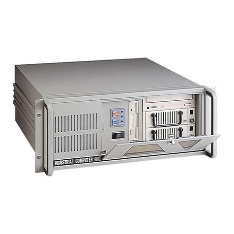
2U carrier grade chassis
Installation guide
MAN1020 Revision 1.2.1

PROPRIETARY INFORMATION
The information contained in this document is the property of Aculab plc and may be the
subject of patents pending or granted, and must not be copied or disclosed without prior
written permission. It should not be used for commercial purposes without prior agreement in
writing.
All trademarks recognised and acknowledged.
Aculab plc endeavours to ensure that the information in this document is correct and fairly
stated but does not accept liability for any error or omission.
The development of Aculab’s products and services is continuous and published information
may not be up to date. It is important to check the current position with Aculab plc.
Copyright © Aculab plc. 2004-2012 all rights reserved.
Document Revision
Rev Date By Detail
1.0.d1 Mar 09 cjb First draft
1.0.d2 Apr 09 cjb DC power added
1.0.d3 Jun 09 cjb Safety information updated, balun information added
1.0.d4 Jul 09 cjb Manual number added, mounting instructions updated
1.0.rc1 Jul 09 cjb Review updates & corrections
1.0.rc2 Aug 09 cjb RAID software information and MAN1015 reference added
1.0.rc3 Oct 09 cjb Review updates
1.0 Oct 09 cjb First release.
1.1 Jan 11 nw Removal, Replacement and Installation of an Aculab
Prosody X card.
1.2 Aug 12 inc Remote management and SNMP reporting sections
added.
1.2.1 Dec 12 ebj Declaration of Conformity added.

Carrier grade groomerII – installation guide
CONTENTS
1Getting started........................................................................................................................ 6
1.1 Unpacking and assembly.................................................................................... 6
1.1.1 Chassis packaging................................................................................... 6
1.1.2 System location........................................................................................ 6
1.1.3 Rack mounting 19 inch equipment........................................................... 6
1.1.4 Airflow and cooling................................................................................... 6
1.1.5 Power connections................................................................................... 7
1.1.6 Earth connection...................................................................................... 7
1.1.7 Connecting AC power.............................................................................. 7
1.1.8 Connecting DC power.............................................................................. 8
1.1.9 Grounding a DC powered system............................................................ 8
1.1.10 Electrostatic discharge precautions......................................................... 8
1.2 2U chassis physical details................................................................................. 9
1.3 Powering the system on ................................................................................... 11
1.4 Powering the system off ................................................................................... 11
1.5 E1/T1 trunk connections................................................................................... 11
1.6 Ethernet connections........................................................................................ 12
1.7 Cabling ............................................................................................................. 12
1.7.1 120 Ohm E1 or 100 Ohm T1 trunk connections ....................................13
1.7.2 75 Ohm E1 trunk connection .................................................................14
1.7.3 10/100 Ethernet VoIP Traffic connections .............................................15
1.7.4 1000BaseT Ethernet IP signalling connection....................................... 16
1.7.5 Cable lengths......................................................................................... 16
1.7.6 RJ45 Connector orientation................................................................... 17
1.8 Ethernet equipment legacy compatibility.......................................................... 17
1.9 System initialisation.......................................................................................... 17
1.10Cabling checks when system is operational..................................................... 17
1.11Checking E1/T1 trunk connection.....................................................................18
1.12Remote management....................................................................................... 18
1.13SNMP reporting................................................................................................ 18
1.13.1 Power supplies....................................................................................... 18
1.13.2 Chassis temperatures............................................................................ 18
1.13.3 System fans ........................................................................................... 18
2Hardware maintenance ........................................................................................................ 20
2.1 Servicing........................................................................................................... 20
2.2 Power module replacement.............................................................................. 20
2.2.1 Removing a power module .................................................................... 21
2.2.2 Replacing a power module ....................................................................21
2.3 Cooling fan replacement................................................................................... 21
2.4 HDD replacement............................................................................................. 22
2.5 Battery replacement.......................................................................................... 22
2.6 Moving an installed GroomerII system .............................................................22
2.7 Common set-up problems ................................................................................ 23
2.7.1 System TDM clock not configured ......................................................... 23
2.7.2 ISDN network/user conflict..................................................................... 23
2.7.3 CAS network conflict.............................................................................. 23
2.7.4 Ethernet IP address conflict................................................................... 23
2.7.5 Ethernet IP address out of range........................................................... 23
2.8 Basic fault finding .............................................................................................24
Appendix A: Warranty and support.......................................................................................... 25
3 of 44

Carrier Grade GroomerII – Installation Guide
A.1 Warranty ...........................................................................................................25
A.2 Returns procedure............................................................................................25
A.3 Spare parts and accessories ............................................................................25
A.4 Contact information...........................................................................................25
A.5 Aculab technical support...................................................................................25
A.6 GroomerII system configuration........................................................................26
Appendix B: Safety information................................................................................................27
B.1 AC Power requirements....................................................................................27
B.2 AC Power cords................................................................................................27
B.3 DC Power requirements....................................................................................28
B.4 Circuit definition ................................................................................................28
B.5 Grounding the system.......................................................................................28
B.6 Serviceable parts..............................................................................................29
B.7 Lithium battery ..................................................................................................29
B.8 Regulatory marking...........................................................................................29
B.9 USA/Canada federal communication commission warnings ............................30
Appendix C: Sicherheitsvorkehrungen....................................................................................31
C.1 Wechselspannungsanforderungen (AC)...........................................................31
C.2 Wechselspannung Anschluss..........................................................................31
C.3 Gleichspannungsanforderungen DC.................................................................32
C.4 Definition des Stromkreises..............................................................................32
C.5 GroomerII - Erdung...........................................................................................33
C.6 Wartungsteile....................................................................................................33
C.7 Lithium Batterien...............................................................................................33
C.8 Regulierungszeichen ........................................................................................33
C.9 Warnungen der Federal Communication Commission der USA und Kanada..34
Appendix D: Earthing requirements for Scandinavia .............................................................35
Appendix E: Technical specifications......................................................................................36
Appendix F: Cabinet mounting options...................................................................................37
Appendix G: Removal, Replacement and Installation of an Aculab Prosody X Card ..........38
G.1 Disassembling the Chassis...............................................................................39
G.2 Removing the PCI Riser Card Assembly..........................................................40
G.3 Removing a Prosody X Card ............................................................................41
G.4 Installing a Prosody X Card ..............................................................................41
G.5 Refitting the PCI Riser Card Assembly.............................................................42
G.6 Reassembling the Chassis ...............................................................................43
3Declaration of Conformance................................................................................................44
Table of figures
Figure 1-1 2U chassis front layout................................................................................................9
Figure 1-2 2U chassis rear layout (dual AC power unit)...................................................... 10
Figure 1-3 Connector numbering................................................................................................11
Figure 1-4 75 Ohm E1 Balun........................................................................................................14
Figure 1-5 RJ45 pin numbering................................................................................................... 17
Figure 1-6 Fan locations................................................................................................................19
Figure G-1 Chassis Disassembly................................................................................................39
4 of 44

Carrier grade groomerII – installation guide
Figure G-2 Removal of the PCI Riser Card Assembly..........................................................40
Figure G-3 Prosody X Card Removal and Installation..........................................................41
Figure G-4 Refitting the PCI Riser Card Assembly................................................................42
Figure G-5 Chassis Reassembly.................................................................................................43
5 of 44

Carrier Grade GroomerII – Installation Guide
1Getting started
1.1 Unpacking and assembly
1.1.1 Chassis packaging
The shipping box contains the following accessories :
•Two IEC 60320 type C13 power cords or two DC power cables
•10/100 Ethernet adapter cables
•E1/T1 splitter cables
•Serial port adapter
The packaging is made from material which can be recycled.
1.1.2 System location
The chassis must be installed in a restricted access location in accordance with IEC 60950-1:
2005 Clause 1.7.14.
1.1.3 Rack mounting 19 inch equipment
WARNING
The chassis weighs up to 20kg. The weight should be taken into consideration
when equipment cabinets and mounting hardware are purchased and installed.
Consult your company health & safety procedures and policies for guidance on
lifting and handling.
Care must be taken to prevent a hazardous condition due to uneven mechanical
loading.
The unit is designed to be mounted on side rails or a shelf inside a 19 inch cabinet.
The rack mount brackets at the front of the unit are designed to hold the rail or shelf
supported unit in place after installation.
If a sliding mounting is used, adequate strain relief should be provided to all cables to
prevent damage when the unit is moved.
1.1.4 Airflow and cooling
CAUTION
The chassis uses forced air-cooling internally. It is imperative that GroomerII
systems are operated with all covers fitted and that none of the ventilation
holes/slots on the front, or rear of the chassis are obstructed.
When rack mounted in a closed or multi-unit cabinet, the operating environment of
the cabinet environment may be greater than the room ambient. In this case
consideration should be given to maintaining an operating environment that does not
exceed 40 °C.
All airflow is front to rear.
6 of 44

Carrier grade groomerII – installation guide
1.1.5 Power connections
The Carrier Grade GroomerII is supplied as either an AC or a DC powered system.
The system will auto adjust to the supplied voltage in AC and DC installations (115 or
230 VAC and -48VDC, see appendix D). Both power cords must be connected to
maintain the standard power module redundancy. The unit will show single PSU
operation via an indicator at the front. The internal power supply is rated at a
maximum of 600W, however the unit is designed to consume no more than 300W
during normal operation (see Appendix E).
Consideration should be given to the connection of the equipment to the supply circuit
and the effect that overloading of the circuits might have on overcurrent protection
and supply wiring. Appropriate consideration of equipment nameplate ratings should
be used when addressing this concern.
1.1.6 Earth connection
Reliable earthing of rack mounted equipment must be maintained. Particular attention
should be given to supply connections other than direct connections to the branch
circuit, such as mains distribution strips that are typically located inside equipment
cabinets.
NOTE
Read the safety information in Appendix B: before installing any
equipment.
1.1.7 Connecting AC power
Each AC power module has a 3 pin socket as shown below (C).
Standard IEC 60320 type C13 power cords provide the AC power and earth
connections. Both modules must be connected to provide power module redundancy.
7 of 44

Carrier Grade GroomerII – Installation Guide
1.1.8 Connecting DC power
Each DC power module has a 2 pin socket as shown below (D).
The mating plug is polarised, and secured by two screws to prevent accidental
disconnection.
Each DC power cable has two terminals to wire to the DC supply. The positive
connection is carried on the red wire and the negative on the black wire. The earth
connection is made via the green/yellow wire.
CAUTION
Observe the correct polarity for DC power connections.
Both modules must be connected to provide power module redundancy.
1.1.9 Grounding a DC powered system
The DC chassis provides two #10-32 threaded studs for chassis enclosure grounding.
Each DC power cord includes a green/yellow earth wire, which should be connected
prior to switching the unit on.
1.1.10 Electrostatic discharge precautions
During installation and maintenance, handle all connectors by their plastic casing or
connector shield. Do not touch metal parts within any socket as you plug connectors
in.
Before plugging in any interface cables, ground yourself to dissipate any static charge
you may be carrying. To do this, ensure the power cords are correctly installed then
briefly touch the exposed metal on the system casing.
These precautions will minimise the chance of any ESD damage to the product.
8 of 44

Carrier grade groomerII – installation guide
1.2 2U chassis physical details
The chassis is designed to fit into 19 inch rack mounting cabinets commonly found in
telecoms switch room and data centre environments.
Width Depth Height Weight
With rack mounts 435mm 508mm 87.6mm Approx 20kg
Without rack
mounts 430mm 508mm 87.6mm Approx 18kg
Figure 1-1 2U chassis front layout
The front of the chassis presents a panel with the following:
•System power/standby switch. Activated by momentary press
•A - System status indicators
•B - One serial port (RJ45)
•C - One USB connector (type A)
NOTE
The RJ45 connector on the front panel is not an Ethernet port.
The system status panel has the following indicators :
9 of 44

Carrier Grade GroomerII – Installation Guide
•B Reset switch
•C –
•D ID switch
•E Critical fault (amber)
•F Major alarm (amber)
•G Minor alarm (amber)
•H Power fault (amber)
•I ID indicator (white)
•J System/signalling IP activity (green)
•K Main power (green)
•L HDD activity (green) or fault (amber)
Card 0
Card 1
Card 2
Figure 1-2 2U chassis rear layout (dual AC power unit)
The rear of the chassis provides access to the following units and interfaces:
•AC or DC power modules with extraction handles (E)
•Gigabit Ethernet connector for IP signalling (two available, K & J above)
•Up to twelve E1/T1 trunk connectors depending on system capacity
•Up to three connectors for VoIP traffic, each containing two fast Ethernet
interfaces
•Two type A USB connectors (H))
•One RJ45 serial port (L)
•Two grounding studs (C)
•PSU health indication – one dual colour LED per power module
•Remote access ethernet port (F)
10 of 44

Carrier grade groomerII – installation guide
0432
1
Figure 1-3 Connector numbering
The VoIP port is on the left of each row of five RJ45 connectors.
NOTE
The rating label for the power supply is visible on the top cover of the
chassis.
1.3 Powering the system on
Connect power cords to the system according to the following procedure:
•Check that the electrical outlet is grounded and it is within the permitted range
shown on the rating label.
•Plug both power cords into the AC or DC power inlet sockets on the rear of the
chassis.
•Connect the other ends of the power cords into suitable electrical outlets.
•Connect E1/T1 or Ethernet network cables as required. The type of cables and
connectors used depend upon the interface mix contained with the system.
•The system may now be powered up by momentarily pressing the power button
on the front panel.
1.4 Powering the system off
An active system can be placed into a low power standby state by momentarily
pressing the power button on the front panel. This will trigger a controlled shutdown of
the operating system software.
In the standby state, the unit can be reactivated by momentarily pressing the power
button on the front panel.
To completely remove all power from the unit, isolate both power inlets from the
mains supply.
It is recommended to maintain a 15 second gap between each power off and power
on cycle.
1.5 E1/T1 trunk connections
Each connector carries connections for two trunks, which must be split into separate
RJ45 connectors prior to attaching to network equipment. Please consult the
GroomerII User Guide for information on identifying trunks.
11 of 44

Carrier Grade GroomerII – Installation Guide
1.6 Ethernet connections
Please consult the GroomerII User Guide for information on configuring IP addresses.
The VoIP Traffic interfaces are designed to connect to full duplex Ethernet switch
equipment, which can sustain the required data throughput with little or no packet
loss. There are two VoIP Traffic interfaces as this can offer additional redundancy, if
required, in a correctly configured network. When both interfaces are connected and
have valid layer 1 connections, the system will default to one interface to carry VoIP
traffic rather than performing load sharing.
Design of a redundant Ethernet network is beyond the scope of this document,
however at a minimum, each VoIP Traffic interface would connect to a separate
Ethernet switch.
1.7 Cabling
GroomerII is connected to other network equipment via CAT 5, 5e, 6 or 6e cables.
There are two types of interface and they have different pin assignments.
The pin-out of the RJ45/48 connectors for both E1/T1 and Ethernet connections are
detailed below. For E1/T1 and 10/100 Ethernet connections :
Receive pairs on the system should be connected to transmit pairs on the network
equipment, and vice versa.
Cross-over cables will be required in instances where two connector sockets with the
same signal pinouts are connected together.
NOTE
E1/T1 crossover cables are wired differently to 10/100 Ethernet crossover
cables.
For Gigabit Ethernet connections, there are four pairs of signals, each transmitting
data in both directions. Cross-over cables are not normally required for Gigabit
Ethernet connections due to auto-sensing procedures built in to the interface
electronics.
NOTE
Shielded cables are recommended in all instances.
Ample strain relief should be fitted when installing all cables, both signal and power.
Any damage caused by inadequate strain relief to cards or power connectors will not
be covered by your warranty.
Both E1/T1 and Ethernet cables may be connected and disconnected while the unit is
active.
Bear in mind that disconnecting an active E1/T1 trunk will cause an alarm condition
both within the GroomerII unit and at the corresponding network end of the cable.
You may wish to check with the network operator if there is a requirement for
advance notification of E1/T1 trunk installation and maintenance.
12 of 44

Carrier grade groomerII – installation guide
1.7.1 120 Ohm E1 or 100 Ohm T1 trunk connections
The system will be provisioned with up to three telecoms interface cards, each of
which has four E1/T1 connectors. In order to provide 8 trunks per card, each
connector carries the wiring for two trunks, and an external splitter cable is required to
break these out to individual E1/T1 RJ45 sockets.
NOTE
The E1/T1 splitter is wired differently to the Ethernet splitter detailed in
1.7.3
Port
RJ45
socket
(TDM)
Aculab card
Port
RJ45
socket
(IP)
Aculab card facelate
AB
Port
B
Port
A
The 8-contact RJ45 Plug on the cable between each individual E1/T1 trunk and the
100 or 120 Ohm network trunk must be wired as follows:
Pin Signal Direction
1 Rx+ input
2 Rx- input
4 Tx+ output
5 Tx- output
Cat 5 screened cabling is recommended for 120 and 100 Ohm trunk connections.
13 of 44

Carrier Grade GroomerII – Installation Guide
1.7.2 75 Ohm E1 trunk connection
NOTE
Each E1 trunk in a GroomerII chassis has configurable impedance.
Some legacy E1 PSTN networks require 75 Ohm trunk connection. The default
impedance for E1 trunks in the GroomerII is 120 Ohm. It is important to confirm with
the network operator which impedance the PSTN is using during the installation
process, as a mismatch can lead to signal degradation and erratic equipment
behaviour that is difficult to diagnose later.
The following signalling services may be expected to be configured for 75 Ohm in
legacy switching equipment which provide the following protocols:
•DASS2
•DPNSS
•SS7/ISUP
•All E1 CAS protocols
Each 75 Ohm trunk is normally connected via a pair of coaxial cables with BNC
connectors. A Balun is available to convert between RJ45 and co-axial cabling. The
Balun also converts between 120 and 75 Ohm interfaces, so the system does not
need to be configured for 75 Ohm operation when this type of converter is used.
Figure 1-4 75 Ohm E1 Balun
14 of 44

Carrier grade groomerII – installation guide
1.7.3 10/100 Ethernet VoIP Traffic connections
This connector is wired to provide two 10/100 LAN interfaces for VoIP traffic.
Pin Signal Direction
1 TxA+ output
2 TxA- output
3 RxA+ input
6 RxA- input
4 TxB+ output
5 TxB- output
7 RxB+ input
8 RxB- input
An adapter cable is supplied to provide access to two separate RJ45 cables.
Connect the adapter cable to the VoIP Traffic ethernet port as shown:
RJ45 Signal RJ45 port 0 RJ45 port 1
1 TxA+ 1
2 TxA- 2
3 RxA+ 3
4 TxB+ 1
5 TxB- 2
6 RxA- 6
7 RxB+ 3
8 RxB- 6
15 of 44

Carrier Grade GroomerII – Installation Guide
NOTE
When connecting the VoIP traffic port to a 10/100BaseT network, the
Ethernet cable adapter should be used. It must always be used when
connecting to a gigabit Ethernet switch.
1.7.4 1000BaseT Ethernet IP signalling connection
There will be a single IP signalling connection per system, and this connector carries
an eight wire Ethernet connection, which does not require an external splitter.
The 8-contact RJ45 Plug on the cable between the chassis and a 1000Base-T
network must be wired as follows:
Pin Signal Direction
1 BI_DA+ bidirect
2 BI_DA- bidirect
3 BI_DB+ bidirect
4 BI_DC+ bidirect
5 BI_DC- bidirect
6 BI_DB- bidirect
7 BI_DD+ bidirect
8 BI_DD- bidirect
Cat 5E, 6 or 6E cabling is recommended for 1000Base-T Ethernet connections, as
this will provide superior noise immunity over longer cable lengths, compared to Cat 5
cabling.
NOTE
When connecting the IP signalling port to a 10/100BaseT network, the
interface will automatically adapt to the lower data rate.
NOTE
Cross-over cables are not typically required for 100BaseT connections.
1.7.5 Cable lengths
Cat 5 cabling is designed for an overall span length of 100m. It is recommended that
the length of either a single point to point cable, or the cumulative length of multiple
cables which may be connected via a patch panel does not exceed 100m. For span
lengths approaching the 100m recommended limit it is important to specify and install
high quality cables.
For E1 trunks converted to BNC cabling, it is recommended that overall span length
is limited to 100m maximum and that 75 Ohm cabling and connectors are used.
Span lengths in excess of 100m may continue to operate. In this case the installer
should check that there is adequate margin on signal levels to maintain expected
service levels.
16 of 44

Carrier grade groomerII – installation guide
1.7.6 RJ45 Connector orientation
RJ45 (US RJ48) Plug
Front View
8 7 6 5 4 3 2 1
Figure 1-5 RJ45 pin numbering
1.8 Ethernet equipment legacy compatibility
The system IP signalling Ethernet interface is designed to operate at Gigabit Ethernet
data rates. If connected to network equipment that is not Gigabit capable, the
interface will attempt to negotiate the highest data rate available.
The GroomerII VoIP traffic interfaces are designed to operate at Fast Ethernet
(100Base-T) data rates. If connected to network equipment that is not Fast Ethernet
capable, the interface will attempt to negotiate a 10Base-T link speed. In most cases
this will impose an artificially low channel count on VoIP connections that will limit the
Groomer system capacity.
CAUTION
The VoIP Traffic interfaces should not be connected directly to legacy “hub” (half
duplex) network equipment.
Modern Ethernet switching equipment operates in a full duplex data mode. It is not
recommended to route VoIP traffic via a network path containing a half duplex ‘hub’
as this will reduce system performance.
1.9 System initialisation
The system start-up process will run automatically at power on, and will start the
Groomer application.
1.10 Cabling checks when system is operational
You can check the continuity of the cabling by looking at the connection state of each
interface via the GroomerII Status Monitor. The Status Monitor will start automatically
when the system is initialised. Full details of Status Monitor views are included in the
GroomerII User Guide.
An E1/T1 trunk with No Signal detected (NOS) means either open circuit on the
receive path or the paths are crossed i.e. RX connected to RX and TX to TX.
An E1/T1 trunk with Remote Alarm Indication Detected (RAI) normally means the
receive path is good but the transmit path may be open circuit.
17 of 44

Carrier Grade GroomerII – Installation Guide
1.11 Checking E1/T1 trunk connection
When all the trunks are connected you may check that the Alarms page of the
GroomerII Status Monitor shows No Alarms Detected on all attached trunks. If a trunk is
showing Alarm Indication Signal (AIS), check the network equipment (switch)
connected to that trunk. All connected trunks must show No Alarms Detected before
you attempt to pass callsthough the system.
1.12 Remote management
The system is fitted with a remote management card that allows Aculab support staff
to access the system should you require their assistance. The card is accessed via
the Ethernet port (F) in figure 1-2.
Follow the instructions in the Intel® Remote Management Module 2 User Guide that
accompanied your system to configure the network and login settings for your card.
CAUTION
Aculab strongly recommends that you change the factory default
Administrator password prior to connecting to an open LAN.
Full instructions for configuring and using the RMM2 module will be found in the
Intel® Remote Management Module 2 User Guide, a copy of which is available on
the GroomerII Installation and Utilities CD accompanying the system.
1.13 SNMP reporting
Later versions of GroomerII application software support SNMP reporting of a number
of system components. The software identifies the components using a generic
numbering system, and the following sections identify the physical location of the
components monitored. Refer to the GroomerII user guide (MAN1015) for details of
the SNMP reports produced.
1.13.1 Power supplies
The power supplies are reported as PSU 1 and PSU 2. When viewed from the rear of
the chassis, PSU 1 is on the right, and PSU 2 is on the left.
1.13.2 Chassis temperatures
Chassis temperatures are reported as T1 and T2. Temperature sensor T1 is located
on the baseboard, whilst sensor T2 is located on the front panel.
1.13.3 System fans
System fans are reported as Fan 1 through Fan 6. The following diagram identifies
the location of each fan.
18 of 44

Carrier grade groomerII – installation guide
Figure 1-6 Fan locations
19 of 44

Carrier Grade GroomerII – Installation Guide
2Hardware maintenance
2.1 Servicing
There are no user serviceable parts inside the GroomerII chassis. The unit may
optionally be powered off for inspection periodically and to remove any dust that
accumulates internally. This should only be performed by qualified technical
personnel.
2.2 Power module replacement
The carrier grade GroomerII is specified to operate with dual redundant power
supplies to provide a high MTBF. In the event of single power module failure, a PSU
fail indicator is lit on the front of the unit. Power module status is available at the rear
of the chassis as follows:
Power supply status LED indication
No input power off
No input power to
module, or fan fail, or
other critical fault
Continuous
amber
Power on with warning
conditions such as slow
fan or high temperature
1Hz blink amber
Standby or forced
shutdown state 1Hz blink green
Power OK, operating
within specification Continuous green
A power module may be removed and replaced with a spare while the unit is
operating. The remaining power module becomes a single point of system failure
while operated in this non-redundant configuration. It is recommended to complete
power module replacements within a two minute period to preserve optimal
environmental conditions within the server. The system should not be operated for
extended periods with one of the PSUs removed for replacement, unless a blanking
plate is fitted to the empty module position.
CAUTION
Observe electrostatic discharge precautions when handling power
modules. Do not touch the gold plated connector while replacing a module.
20 of 44
Table of contents
Other aculab Chassis manuals
