Controls SPEEDLOADER 34-V1082 User manual

MANUALE DI ISTRUZIONI
INSTRUCTION
34-V1082–V1084
SPEEDLOADER
Digital Automatic Universal Tester


Manuale di Istruzioni Instruction Manual
34-V1082-84 | Rev. 1 | EN | 28.02.2023 | wwww.controls-group.com
Page i
Index
1.INTRODUCTION 1
1.1Icons appearing in the manual .............................................................................................................2
1.2Manual revision history..........................................................................................................................2
1.3Symbols used ..........................................................................................................................................2
1.4Intended use and improper use ...........................................................................................................3
1.5Safety information ..................................................................................................................................4
1.6Environmental risks and disposal.........................................................................................................8
1.7Identification plate..................................................................................................................................9
1.8CE declaration .........................................................................................................................................9
2.DESCRIPTION 10
2.1Commands and controls......................................................................................................................11
2.1.1Control unit............................................................................................................ 12
2.2Technical specifications .......................................................................................................................13
3.INSTALLATION 14
3.1Shipment................................................................................................................................................15
3.2Unpacking and inspection ...................................................................................................................16
3.2.1How to remove the equipment from the shipping crate ................................ 17
3.3Positioning of the unit and space requirements ..............................................................................18
3.4Electrical requirements ........................................................................................................................19
3.5Connections...........................................................................................................................................20
4.USE OF THE EQUIPMENT 21
4.1Preliminary operations.........................................................................................................................22
4.2Setup for Marshall test.........................................................................................................................23
4.3Setup for digital CBR test .....................................................................................................................27
4.4Setup for indirect tensile test ..............................................................................................................30
4.5Turning ON and using the equipment ...............................................................................................34
4.6Commands and controls of the control unit .....................................................................................35
4.7Operator’s interface description.........................................................................................................36
4.7.1TEST EXECUTION menu.......................................................................................... 36
4.7.1.1TEST PARAMETERS menu ....................................................................................... 37
4.7.1.2START TEST menu................................................................................................... 44
4.7.2OPTIONS menu ...................................................................................................... 46
4.7.2.1CHANGE LANGUAGE menu .................................................................................... 46
4.7.2.2SETTINGS menu...................................................................................................... 47
4.7.3RS232 serial port................................................................................................... 51

Manuale di Istruzioni Instruction Manual
34-V1082-84 | Rev. 1 | EN | 28.02.2023 | wwww.controls-group.com
Page ii
4.7.4MANUAL COMMANDS menu ................................................................................. 52
4.7.5CALIBRATION menu ............................................................................................... 53
4.8Carry out a test .....................................................................................................................................54
4.8.1Setting the TEST PARAMETERS .............................................................................. 55
4.8.2Testing a sample................................................................................................... 56
4.9Stopping the cycle via the Emergency button...................................................................................60
4.10Switching off the unit ...........................................................................................................................60
5.MAINTENANCE 61
5.1Operator’s preventive maintenance...................................................................................................62
5.2Authorized service engineer maintenance actions ..........................................................................62
5.2.1Greasing of the ram screw .................................................................................. 63
5.2.2Manual movement of the crosshead................................................................. 65
5.2.3Calibration verification......................................................................................... 66
5.2.4Calibration ............................................................................................................. 67
6.DIAGNOSTICS 70
6.1System (Hidden) menus.......................................................................................................................71
6.1.1Hidden menu (Factory Menu)............................................................................. 71
This instruction manual is an integral part of the machine and should be read before using the machine and
be safely kept for future reference.
CONTROLS reserves all rights of this manual, no part or whole can be copied without the written
permission of CONTROLS.
The proper use of this machine must be strictly adhered to, any other use must be considered as incorrect.
The manufacturer cannot be held responsible for damage caused by incorrect use of the machine.
The machine must not be tampered with for any reason. In case of tampering, the manufacturer declines
any responsibility of functioning and safety of the machine.
This Manual is published by CONTROLS.
CONTROLS reserves the right to update its manuals without notification in order to correct possible typing
errors, mistakes, updating of information and/or updating of programs and/or accessories.
Such changes will be inserted in the latest edition of the current manual.
This present version of the manual. Printed in Italy

Manuale di Istruzioni Instruction Manual
34-V1082-84 | Rev. 1 | EN | 28.02.2023 | wwww.controls-group.com Page 1
1. INTRODUCTION
NOTE:
The present manual is updated for the product it is sold with in order to grant an adequate
reference in operating and maintaining the equipment.
The manual may not reflect changes to the product not impacting service operations.
The SPEEDLOADER tester is a machine used for road testing lab. The CBR and Marshall tests, Indirect
Tensile tests, Quick Triaxial tests, Unconfined and Uniaxial soil tests, and all tests that can be performed
under displacement control are all possible with the 50 kN capacity and the fully variable test speed of
0.2 to 51 mm/min. To meet the needs of either the field or the central laboratory, the machine can be
fitted with analogical or digital load/displacement measurement systems as well as dedicated
accessories.
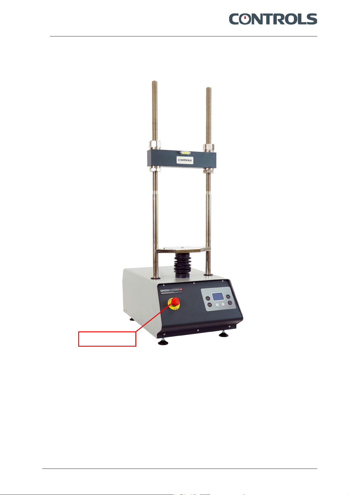
The rigid two-column structure of the SPEEDLOADER tester includes an upper cross beam that can be
adjusted in height. The load jack, DC motor, and controls are integrated into a base cabinet with a
unique design. The machine's processor, with a memory up to 300 tests, gathers and processes test
data.
The user can control the test speed with the new Automatic Variable Speed 50 kN Load Frame, which is
easily adjustable and displayed on the digital display. Furthermore, the test stroke can be predefined at
the start of the test with an automatic stop, preventing overloading of the device and the test subject
and ensuring operator safety. This significant element also allows the operator to calibrate the machine's
speed using micrometric adjustments. The lower platen's motion direction is also showcased on the
display. Two operating leds—one for machine switched on and the other for travel direction—and an
emergency button also are installed on the front panel.
Main features:
The firmware provide the digital speed control and a number of important test functions as follows:
Closed loop speed control
CBR and MARSHALL test speed can be selected by default.
Other testing speeds (Custom) between 0.2 and 51 mm/min, can be easily set.
Selection of maximum platen displacement.
The automatic stop of the machine avoids machine and specimen overloading, thus assuring
operator safety.
Rapid approach function, to reduce the testing time.
Rapid platen return to speed up the platen base return at the end of the test.
Speed calibration function by firmware. The test speed is originally factory calibrated using a
polynomial interpolation. A test point is provided to verify the speed with a standard tachometer.
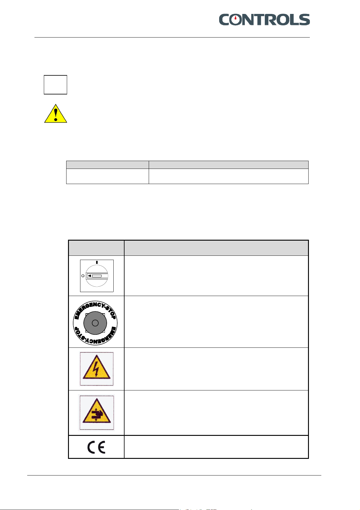
Emergency stop button as required by the CE prescriptions.
The following models are available:
34-V1082
SPEEDLOADER compression testing machine with digital control panel, motorized ram, two-
column structure and adjustable crossbeam.
220-240V/50-60Hz/1Ph
34-V1084
SPEEDLOADER compression testing machine with digital control panel, motorized ram, two-
column structure and adjustable crossbeam.
110V/60Hz/1Ph
Please read this manual thoroughly before you start using the equipment

Manuale di Istruzioni Instruction Manual
34-V1082-84 | Rev. 1 | EN | 28.02.2023 | wwww.controls-group.com
Page 2
1.1 Icons appearing in the manual
This icon indicates a NOTE; please read thoroughly the items marked by this picture.
This icon indicates a WARNING message; the items marked by this icon refer to the safety
aspects of the operator and/or of the service engineer.
1.2 Manual revision history
Revision/Date Change description
Rev. 1
28/02/2023
Manual release
1.3 Symbols used
In this manual and on the equipment itself, apart from the symbols indicated on the control
panel, the following icons are also used:
Symbol Description
Mains switch:
O = device not connected to the mains line
I = device connected to the mains line
Emergency button
Dangerous voltage
Hand injury
Conformity to the CE Directive

Manuale di Istruzioni Instruction Manual
34-V1082-84 | Rev. 1 | EN | 28.02.2023 | wwww.controls-group.com
Page 3
1.4 Intended use and improper use
The equipment SPEEDLOADER can only be used for the execution of the tests CBR, Marshall,
Quick Triaxial, Unconfined, Splitting Tensile, and any other static test to be carried out under
speed control (admitted speed range 0,2 – 51mm/min) and with a maximum capacity of 50kN,
using the relevant accessories supplied by CONTROLS, according to the following International
Standards:
ASTM D1559
ASTM D5581
AASHTO T245
EN 12697-12
EN 12697-23
EN 12697-34
AASHTO T193
NF P98-251-1/4
ASTM D6927
ASTM D1883
BS 1377:4
BS 598:107
EN 13286-47
UNI 10009
NF P94-078
DIN 1996
CNR 30
CNR 34
The unit is designed to be operated by one operator that has to install the necessary
accessories, load-unload the sample and start the test.
During normal operation the working area of the equipment is its front part where the
operator’s controls are located.
The operator is responsible for switching on the device, carrying out the operations for which
the device was designed and manufactured, switching off the device at the end of the test or in
the case of an emergency.
The operator must be trained on the correct use of the device and the relative safety aspects
of its use.
The device should be used following the procedures described in this manual.
Never use the device for reasons other than those for which it was designed and
manufactured. Any other use of the device is to be considered improper, not foreseen and
hence dangerous.
CONTROLS will not be responsible for improper use of the instrument.

Manuale di Istruzioni Instruction Manual
34-V1082-84 | Rev. 1 | EN | 28.02.2023 | wwww.controls-group.com
Page 4
1.5 Safety information
WARNING:
Please read this chapter thoroughly.
CONTROLS designs and builds its devices complying with the related safety requirements;
furthermore it supplies all information necessary for correct use and the warnings related to
use of the equipment.
CONTROLS will not to be held responsible for:
use of the equipment different than the intended use,
damages to the unit, to the operator, caused both by installation and maintenance
procedures different than those described in this manual supplied with the unit, and by
wrong operations,
mechanical and/or electrical modifications performed during and after the installation,
different than those described in this manual
The unit is not designed to be used in an explosive atmosphere.
Installation and any technical intervention must only be performed by qualified technicians
authorized by CONTROLS.
Only authorised personnel can remove the covers and/or have access to the components
under voltage.
During normal use, if the operator detects irregularities or damages, he/she should
immediately inform the authorized technical personnel.
Maintenance and service activities can only be performed by skilled authorized technical
personnel that have been properly trained on the residual risks of the equipment.
It is responsibility of the purchaser to make sure that the operators have been properly
instructed concerning the safety issues and the residual risks related to the equipment.

Manuale di Istruzioni Instruction Manual
34-V1082-84 | Rev. 1 | EN | 28.02.2023 | wwww.controls-group.com
Page 5
The machine is equipped with the following devices to limit the residual risks in using it:
Emergency button that allows stopping the motor when dangerous conditions are
encountered.
Fig. 1-1
Access panels to internal devices fixed with screws.
Emergency button

Manuale di Istruzioni Instruction Manual
34-V1082-84 | Rev. 1 | EN | 28.02.2023 | wwww.controls-group.com
Page 6
The following table lists those parts of the equipment that may present some residual risks for
the safety of the personnel if the instructions provided in this manual are not duly followed
Personnel Area with residual risks
Operator Area near the sample and relevant accessories; keep hands away to avoid
crushing.
Technical personnel Above listed areas
Areas around compartments closed by removable panels
Areas around compartments that contain electrical parts
For continued fire protection, replace fuses with same type and rating. Also, in
case of failure, components may only be replaced by using original spare parts.
It is in the responsibility of the purchaser to ensure that fire prevention policies
are properly implemented according to the CE provisions.
Personnel responsible
of transportation and
moving of the
equipment
Raising and moving of the equipment from the wooden crate must be
performed by people properly trained and equipped with suitable personal
protection devices (e.g. gloves, helmet, etc.). Failure to follow the instructions
above may endanger the personnel involved.
Here follows a list of all WARNINGs present in the manual;
please see relevant chapters for full details on each related safety issue.
WARNING:
When operating with the covers open/removed and the unit is attached to the mains line, care
must be taken as high voltage is present in some parts of the unit (e.g. electrical panel). Only
authorized and qualified service technicians are allowed to open /remove covers.
WARNING:
All safety devices must be functional at all times. Damaged protective covers or devices must
be replaced immediately. When safety components are replaced, the protective devices are to
be properly attached and tested. Any manipulation of the safety devices endangers the
operating personnel.
WARNING:
Raising and moving of the equipment must be performed by people properly trained and
equipped with suitable personal protection devices (e.g. gloves, helmet, etc.). Failure to follow
the instructions above may endanger the personnel involved.
WARNING:
The wooden crate is high; be careful in balancing while raising it.
WARNING:
If the instructions to remove the equipment from the shipping box are not carefully followed,
damages to the equipment cabinet may result. This will void the warranty terms of the
equipment.
WARNING:
Do not stand under suspended loads

Manuale di Istruzioni Instruction Manual
34-V1082-84 | Rev. 1 | EN | 28.02.2023 | wwww.controls-group.com
Page 7
WARNING:
Considering the weight of the equipment and the footprint (see chapter 2.2), check the
maximum allowed floor load before installation.
WARNING:
If the equipment is brought from a cold environment into a heated room, condensation on
and in the unit can constitute a danger and lead to malfunctioning of the unit when started.
Wait to connect and operate the unit until it is at room temperature.
WARNING:
The general grounding must comply with the rules in force; a wrong quality of the grounding
could be dangerous for the operator’s safety and cause bad function of the electrical devices.
WARNING:
Covers/doors can only be removed/opened by maintenance people, by using relevant
tools/keys. These tools and keys are for use by maintenance personnel only. Never leave the
tools and keys attached to the unit as this may endanger operator safety.
After performing maintenance/repair, make sure that all covers/doors are properly closed and
locked.
WARNING:
The functions of the HIDDEN MENU are reserved to CONTROLS authorized technical
personnel. Do not access these functions unless specifically instructed/authorized by
CONTROLS. CONTROLS will not be held responsible for damage caused to good
or persons due to unauthorized use of these functions.
WARNING:
The TRAVEL LIMIT is not a safety function. Do not rely on it for the safety of the operator
and/or to prevent damages to the accessories used during the tests.
WARNING:
Failing to perform the recommended maintenance actions or maintenance performed by
unauthorized people can void the warranty.
CONTROLS will not be responsible for maintenance and service actions performed by
unauthorized people.
WARNING:
Before opening/removing the covers, disconnect the mains supply to the device and wait at
least 5 minutes.
WARNING:
For continued fire protection, replace fuses with same type and rating. Also, in case of failure,
components may only be replaced by using original spare parts. It is in the responsibility of the
purchaser to ensure that fire prevention policies are properly implemented according to the
CE provisions.

Manuale di Istruzioni Instruction Manual
34-V1082-84 | Rev. 1 | EN | 28.02.2023 | wwww.controls-group.com
Page 8
WARNING:
Avoid pouring water, even accidentally, or other liquids into the device, as this could cause
short circuits. Before cleaning the device, disconnect it from the mains line.
WARNING:
Refer to qualified service organization authorized by CONTROLS to carry out the maintenance
actions described in the chapter “Authorized service engineer maintenance action”. CONTROLS
has not to be held responsible for damages to the equipment and/or injuries to personnel in
case the above is not strictly followed.
WARNING:
The upper movement of the platen is not monitored and limited by a limit switch. It is
therefore responsibility of the operator to make sure the platen position will not exceed the
allowed upper limit. CONTROLS will not be considered responsible for damages to the
equipment resulting for improper use.
WARNING:
The RESET functions of the HIDDEN MENU is reserved to CONTROLS authorized technical
personnel. Do not access this function unless specifically instructed/authorized by CONTROLS.
CONTROLS will not be held responsible for damage caused to good
or persons due to unauthorized use of these functions.
WARNING:
For continued fire protection, replace fuses with same type and rating. Also, in case of failure,
components may only be replaced by using original spare parts.
1.6 Environmental risks and disposal
INFORMATION TO THE OWNER OF THE EQUIPMENT
The above symbol, when attached to the equipment or to the relevant packaging, indicates
that the product must be disposed of separately from other rubbish at the end of its useful
life.
Therefore, at the end of its useful life, the owner should dispose of the product in a suitable
collection point for electrical and electronic products provided by the local authorities.
The correct disposal of this product and the subsequent treatment encourages the
manufacture of products using re-cycled materials and limits the environmental impact of the
product caused by improper disposal.
Improper disposal of the product is subject to penalties as foreseen by the local regulations.

Manuale di Istruzioni Instruction Manual
34-V1082-84 | Rev. 1 | EN | 28.02.2023 | wwww.controls-group.com
Page 9
1.7 Identification plate
The identification plate is located on the rear panel of the equipment, near the socket of the power cable.
1.8 CE declaration
This page shows a copy of the CE declaration. The original is supplied with the equipment as a
separate document.
.

Manuale di Istruzioni Instruction Manual
34-V1082-84 | Rev. 1 | EN | 28.02.2023 | wwww.controls-group.com
Page 10
2. DESCRIPTION
Refer to the following figures for main components identification.
Fig. 2-1
Ref. Description
1 Upper and lower locknuts to adjust the height of the crossbeam
2 Upper crossbeam
3 Accessories attachment point
4 Lower crossbeam
5 Keyboard with Display
6 Spirit Level
1
1
3
2
1
1
5
4
6

Manuale di Istruzioni Instruction Manual
34-V1082-84 | Rev. 1 | EN | 28.02.2023 | wwww.controls-group.com
Page 11
2.1 Commands and controls
This chapter describes the commands and controls of the equipment.
Fig. 2-2
Fig. 2-3
Ref. Description
1 Mains switch (on rear panel)
2 Keyboard with Display
3 Emergency button
1
2
3

Manuale di Istruzioni Instruction Manual
34-V1082-84 | Rev. 1 | EN | 28.02.2023 | wwww.controls-group.com
Page 12
2.1.1 Control unit
Fig. 2-4
Rif. Description
1 SET button - used to go to PREVIOUS screen or digit
2 ENTER button – used to go to NEXT screen or digit
3 START button – used to start the current test
4 ESC/STOP button – used to stop the current test or exit test screen
5 UP button – used to raise the selected number or digit by 1
6 DOWN button - used to lower the selected number or digit by 1
7 DISPLAY
3
1
5 6
4
2
7

Manuale di Istruzioni Instruction Manual
34-V1082-84 | Rev. 1 | EN | 28.02.2023 | wwww.controls-group.com
Page 13
2.2 Technical specifications
Main characteristics
Product SPEEDLOADER
Digital Automatic Universal Tester for Displacement
Controlled Tests
Manufacturer CONTROLS Liscate (MI) Italy
Product code 230VAC/50-60Hz/1 Ph version
Product code 110VAC/60Hz/1 Ph version
34-V1082
34-V1084
Max. capacity 50 kN
Test speed Adjustable from 0.2 mm/min to 51 mm/min
Horizontal daylight 270 mm
Vertical daylight 730 mm
Max. piston travel 100 mm
Single-phase line voltage 110 VAC/220VAC/230 VAC +6%, -10%
Frequency 50/60 Hz
Power DC motor 750 W
Method of power entry Power cable with plug
Net weight (machine only, without accessories,
approx.)
89 Kg
Overall dimensions (W x D x H) 425 x 670 x 1265 mm
Environmental conditions
Operating temperature + 10 + 40°C
Operating humidity ≤50%RH @ 40°C

Manuale di Istruzioni Instruction Manual
34-V1082-84 | Rev. 1 | EN | 28.02.2023 | wwww.controls-group.com
Page 14
3. INSTALLATION
The instructions indicated in this chapter enable you to perform a correct installation and
interfacing in order to grant a regular operation of the equipment.
Included are initial inspection procedure, power requirements and instructions for installing
the unit.
The information in this chapter is intended for authorized service-trained personnel.
CONTROLS can supply the assistance and the necessary technical advice for pre-installation,
all the pre-installation phases are at the purchaser’s charge and must be performed complying
with the indications given below.
WARNING:
When operating with the covers open/removed and the unit is attached to the mains line, care
must be taken as high voltage is present in some parts of the unit (e.g. electrical panel). Only
authorized and qualified service technicians are allowed to open /remove covers.
WARNING:
All safety devices must be functional at all times. Damaged protective covers or devices must
be replaced immediately. When safety components are replaced, the protective devices are to
be properly attached and tested. Any manipulation of the safety devices endangers the
operating personnel.

Manuale di Istruzioni Instruction Manual
34-V1082-84 | Rev. 1 | EN | 28.02.2023 | wwww.controls-group.com
Page 15
3.1 Shipment
The equipment is normally shipped in a wooden crate having the following dimensions and
gross weight depending on the model:
Model Gross
weight
Overall dimensions
(W x D x H)
Minimum
fork lift
length
V1082 – V1084 209 Kg 680 x 780 x 1400 mm 1200 mm
Use a proper fork lift with minimum fork length as above indicated to raise and move the
wooden crate (see figure below).
Fig. 3-1
WARNING:
Raising and moving of the equipment must be performed by people properly trained and
equipped with suitable personal protection devices (e.g. gloves, helmet, etc.). Failure to follow
the instructions above may endanger the personnel involved.
WARNING:
The wooden crate is high; be careful in balancing while raising it.

Manuale di Istruzioni Instruction Manual
34-V1082-84 | Rev. 1 | EN | 28.02.2023 | wwww.controls-group.com
Page 16
3.2 Unpacking and inspection
The unit was carefully checked both mechanically and electrically before shipment; it should
be inspected for any damage that may have occurred in transit.
NOTE:
If the shipping container or packaging material is damaged, it should be kept until the unit has
been mechanically and electrically checked.
If there is mechanical damage and/or the contents are incomplete (see the shipping list),
please notify the local CONTROLS representative.
If the shipping container is damaged or shows sign of stress, notify the carrier as well as the
CONTROLS representative. Save the shipping material for carrier’s inspection. Also take some
pictures.
Here follows the procedure for the unpacking of the equipment.
This manual suits for next models
1
Table of contents
Other Controls Test Equipment manuals