ADC SL20 Gen II User manual

SL20 Gen II
Parts Manual
Phase 7
American Dryer Corporation
88 Currant Road
Fall River, MA 02720-4781
Telephone: (508) 678-9000 / Fax: (508) 678-9447
E-mail: techsupport@amdry.com
www.amdry.com
ADC Part No. 450599-2

We have tried to make this manual as complete as possible and hope you will find it useful. ADC reserves the right to
make changes from time to time, without notice or obligation, in prices, specifications, colors, and material, and to
change or discontinue models.
Important
For your convenience, log the following information:
DATE OF PURCHASE ____________________________________________________ MODEL NO. ______________
RESELLER’S NAME _________________________________________________________________________________
Serial Number(s)_____________________________________________________________________________________
____________________________________________________________________________________________________
____________________________________________________________________________________________________
Replacement parts can be obtained from your reseller or theADC factory. When ordering replacement parts from the
factory,you canFAXyour ordertoADCat (508)678-9447ortelephone your order directly totheADCPartsDepartment
at (508) 678-9000. Please specify the dryer model number and serial number in addition to the description and part
number, so that your order is processed accurately and promptly.
The illustrations on the following pages may not depict your particular dryer exactly. The illustrations are a composite
of the various dryer models. Be sure to check the descriptions of the parts thoroughly before ordering.
Retain This Manual In ASafe Place For Future Reference
American Dryer Corporation products embody advanced concepts in engineering, design, and safety. If this product
is properly maintained, it will provide many years of safe, efficient, and trouble free operation.
ONLY qualified technicians should service this equipment.
OBSERVE ALL SAFETY PRECAUTIONS displayedon the equipment or specified in the installation manual included
with the dryer.
The following “FOR YOUR SAFETY” caution must be posted near the dryer in a prominent location.
FORYOURSAFETY
Do not store or use gasoline or
other flammable vapors and
liquidsinthevicinityofthisor
anyotherappliance.
POURVOTRESÉCURITÉ
Ne pas entreposer ni utiliser d’essence
nid’autresvapeursouliquides
inflammables à proximité de cet appareil
oudetoutautreappareil.
SL20 PH7
“IMPORTANT NOTE TO PURCHASER”
Information must be obtained from your local gas supplier on the
instructions to be followed if the user smells gas. These
instructionsmustbepostedinaprominentlocation near the dryer.

Table of Contents
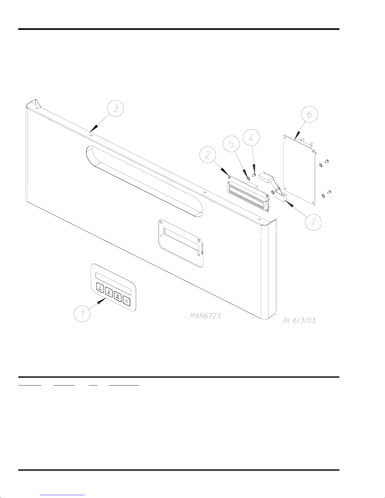
Phase7.3 Non-CoinTopPanelAssembly forTopControl Models...............................................................................4
Phase7.5 Non-CoinTopPanelAssembly forTopControl Models...............................................................................5
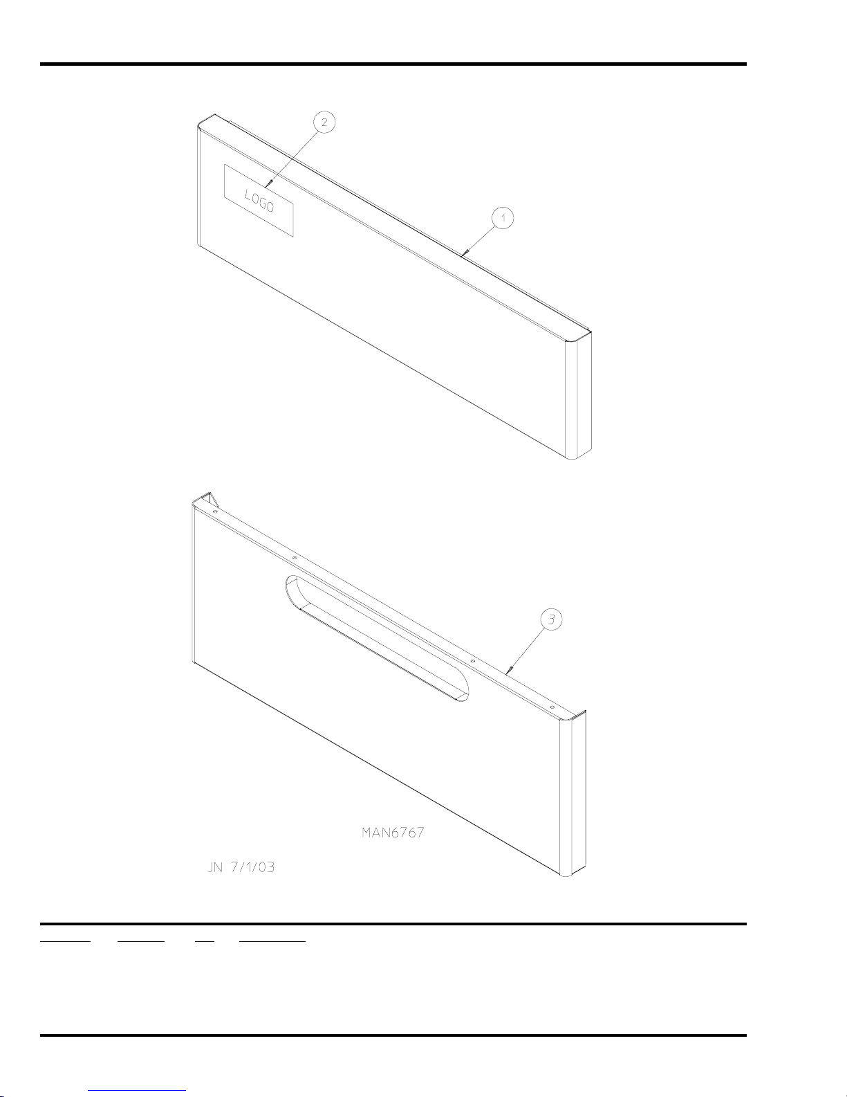
Front PanelAssemblies ..............................................................................................................................................6
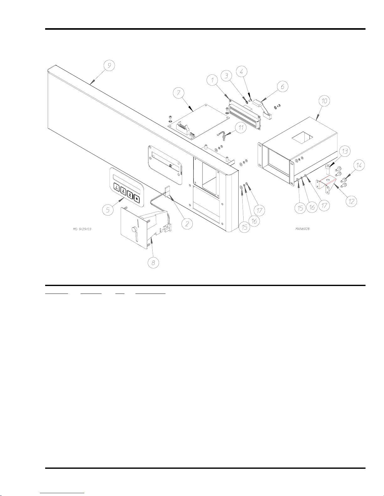
Phase 7.5 Non-Coin Bottom PanelAssembly for Bottom Control Models ...................................................................7
Phase 7.3 Non-Coin Bottom PanelAssembly for Bottom Control Models ...................................................................8
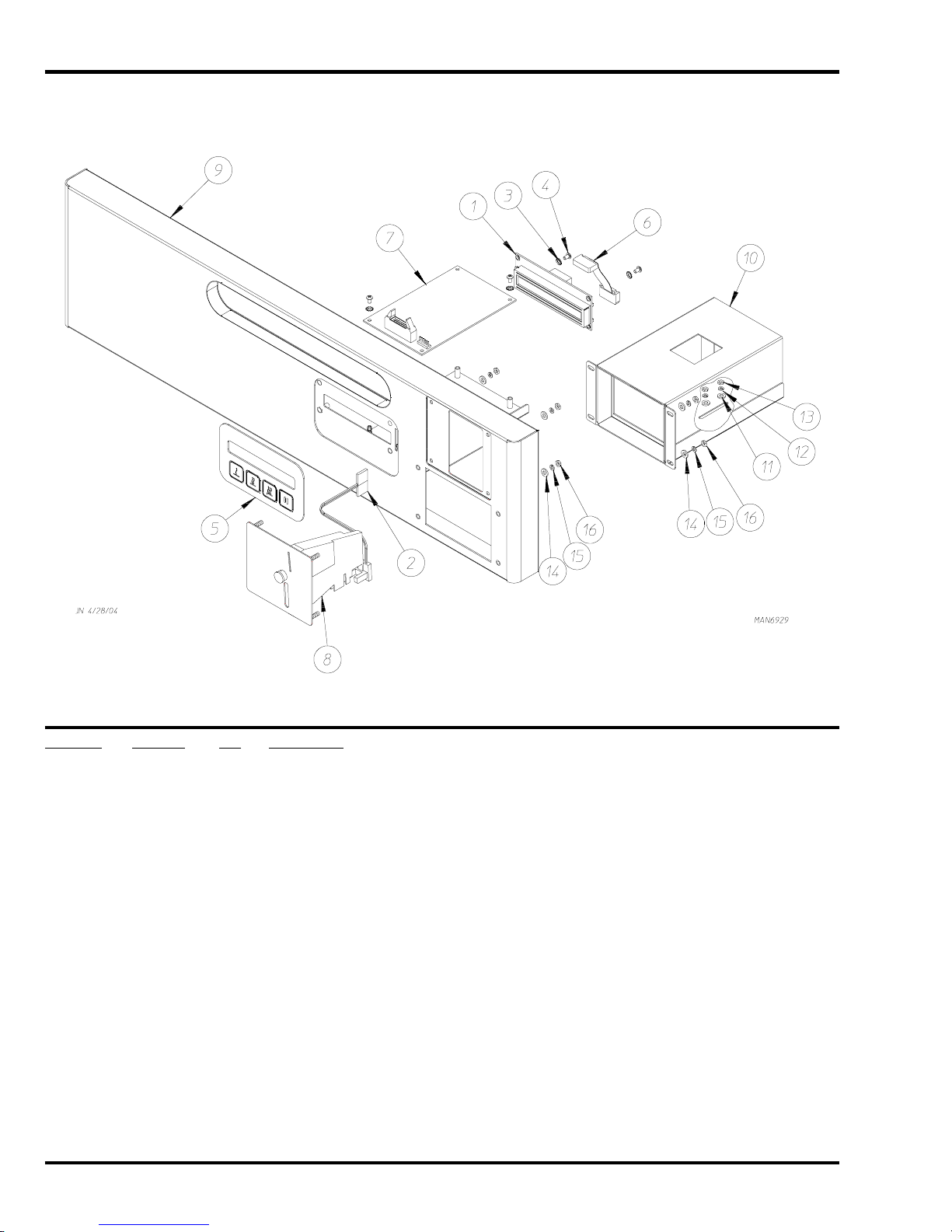
Phase 7.3 Coin Top PanelAssembly for Top Control Models ......................................................................................9
Phase 7.3 Coin Bottom PanelAssembly for Bottom Control Models ........................................................................10
MainDoorAssemblies .............................................................................................................................................. 11
Middle Front PanelAssembly ...................................................................................................................................12
Lint DrawerAssembly for Models Mfd. as of July 29, 2005 .......................................................................................13
Lint DrawerAssembly for Models Mfd. prior to July 29, 2005 ....................................................................................14
TumblerAssembly for Models Mfd. as of May 2004 ..................................................................................................15
TumblerAssembly for Models Mfd. prior to May 2004...............................................................................................16
RearSupport PanelAssembly ..................................................................................................................................17
FrontTumbler WheelAssemblies .............................................................................................................................18
RearTumblerWheelAssemblies ..............................................................................................................................19
Fire Suppression System PipingAssembly ..............................................................................................................20
TemperatureSensorAssemblies...............................................................................................................................21
MotorDriveAssembly ...............................................................................................................................................22
Direct SparkIgnition BurnerAssembly ......................................................................................................................24
Lint Box / Blower MotorAssembly ............................................................................................................................26
Electric OvenAssembly ............................................................................................................................................28
BlowerAssembly ......................................................................................................................................................29
BlowerMotorAssembly ............................................................................................................................................30
Front Electrical PanelAssembly...............................................................................................................................31
Sail Switch Assembly ...............................................................................................................................................32
Base / Top / Sides / Back Guard Assemblies ...........................................................................................................33
Pedestal Box Option.................................................................................................................................................34
AdditionalPartsAvailable .........................................................................................................................................35

4 American Dryer Corporation 450599-2
Phase 7.3 Non-Coin Top Panel Assembly
ForTopControlModels
Illus. No. Part No. Qty.Description
1 112579 1 Phase 7 Keypad
2 137250 1 Phase 7 Ribbon Cable
3 137270 1 Large Character Display
4 150005 4 #6-32 x 1/4” Phillips Round Head Machine Screw
5 153010 4 #6 Star Washer
6 887012 1 Phase 7.3.2 Board with a Fire Suppression System
(for models mfd. as of January 22, 2004)
887009 1 Phase 7.3.2 Board with a Fire Suppression System
(for models mfd. prior to January 22, 2004)
7 818482 1 Black Control Panel
8 ––––––* 1 Logo ONLY
9 818206 1 Magnetic Switch
* Contact reseller for logo.

450599-2 www.amdry.com 5
Phase 7.5 Non-Coin Top Panel Assembly
ForTop Control Models
Illus. No. Part No. Qty.Description
1 112580 1 Phase 7.5 Non-Coin Keypad
2 153010 3 #6 Star Washer
3 150005 3 #6-32 x 1/4” Phillips Round Head Machine Screw
4 887020 1 Phase 7.5 Non-Coin Board with a Fire Suppression System
5 818463 1 Non-Coin Top Control Panel
6 818206 1 Magnetic Switch

6 American Dryer Corporation 450599-2
Front Panel Assemblies
Illus. No. Part No. Qty.Description
1 818478 1 Top Control Panel for Bottom Controls
2 ––––––* – Logo ONLY
3 818466 1 Front Bottom Panel Assembly for Top Controls
* Contact reseller for logo.

450599-2 www.amdry.com 7
Phase 7.5 Non-Coin Bottom Panel Assembly
ForBottomControlModels
Illus. No. Part No. Qty.Description
1 112580 1 Phase 7.5 Non-Coin Keypad
2 887020 1 Phase 7.5 Non-Coin Board with a Fire Suppression System
3 153010 3 #6 Star Washer
4 150005 3 #6-32 x 1/4” Phillips Round Head Machine Screw
5 818465 1 Phase 7.5 Non-Coin Bottom Control Panel

8 American Dryer Corporation 450599-2
Phase 7.3 Non-Coin Bottom Panel Assembly
ForBottomControlModels
Illus. No. Part No. Qty.Description
1 112579 1 Phase 7.3 Keypad
2 137270 1 Large Character Display
3 818436 1 Non-Coin Bottom Control Panel
4 150005 4 #6-32 x 1/4” Phillips Round Head Machine Screw
5 153010 4 #6 Star Washer
6 887012 1 Phase 7.3.2 Board with a Fire Suppression System
(for models mfd. as of January 22, 2004)
887009 1 Phase 7.3.2 Board with a Fire Suppression System
(for models mfd. prior to January 22, 2004)
7 137250 1 Ribbon Cable

450599-2 www.amdry.com 9
Phase 7.3 Coin Top Panel Assembly
ForTop Control Models
Illus. No. Part No. Qty.Description
1 137270 1 Large Character Display
2 883774 1 Optic Switch
3 153010 4 #6 Star Washer
4 150005 4 #6-32 x 1/4” Phillips Round Head Machine Screw
5 112579 1 Phase 7.3 Coin Keypad
6 137250 1 Phase 7.3 Ribbon Cable
7 887011 1 Phase 7.3.2 Board without a Fire Suppression System
(for models mfd. as of January 22, 2004)
887012 1 Phase 7.3.2 Board with a Fire Suppression System
(for models mfd. as of January 22, 2004)
887009 1 Phase 7.3.2 Board with a Fire Suppression System
(for models mfd. prior to January 22, 2004)
8 884029 1 25¢ US Optic Coin Acceptor
9 818467 1 Black Control Panel
10 818132 1 Coin Vault for Top Control
11 818206 1 Magnetic Switch
12 818500 1 Coin Vault Bracket
13 150511 1 1/4-20 x 1” Tap Bolt
14 150300 4 #10-16 x 1/2” Hex Washer TEK Screw
15 153000 8 #8 Flat Washer
16 153012 8 #8 Star Washer
17 152015 8 #8-32 Hex Nut

10 American Dryer Corporation 450599-2
Phase 7.3 Coin Bottom Panel Assembly
ForBottomControlModels
Illus. No. Part No. Qty.Description
1 137270 1 Large Character Display
2 883774 1 Optic Switch
3 153010 4 #6 Star Washer
4 150005 4 #6-32 x 1/4” Phillips Round Head Machine Screw
5 112579 1 Phase 7.3 Coin Keypad
6 137250 1 Phase 7.3 Ribbon Cable
7 887011 1 Phase 7.3.2 Board without a Fire Suppression System
(for models mfd. as of January 22, 2004)
887012 1 Phase 7.3.2 Board with a Fire Suppression System
(for models mfd. as of January 22, 2004)
887009 1 Phase 7.3.2 Board with a Fire Suppression System
(for models mfd. prior to January 22, 2004)
8 884029 1 25¢ US Optic Coin Acceptor
9 818424 1 Black Control Panel
10 818422 1 Coin Vault for Bottom Control
11 153049 2 13/64” x 7/8” Flat Washer
12 153024 2 #10 Lock Washer
13 152015 2 #8 Hex Nut
14 153049 2 13/64” x 7/8” Flat Washer
15 153012 8 #8 Star Washer
16 152015 8 #8-32 Hex Nut

450599-2 www.amdry.com 11
Main Door Assemblies
Illus. No. Part No. Qty.Description
1 883824 1 Door Pan with Glass
2 818832 1 Door Assembly Complete (right hinge) Stainless Steel
(for models mfd. as of October 25, 2004)
(includes illus. nos. 1 through 13)
818830 1 Door Assembly Complete (right hinge) White
(for models mfd. as of October 25, 2004)
(includes illus. nos. 1 through 13)
818833 1 Door Assembly Complete (left hinge) Stainless Steel
(for models mfd. as of October 25, 2004)
(includes illus. nos. 1 through 13)
818831 1 Door Assembly Complete (left hinge) White
(for models mfd. as of October 25, 2004)
(includes illus. nos. 1 through 13)
818562 1 Door Assembly Complete (right hinge) Stainless Steel
(for models mfd. prior to October 25, 2004)
(includes illus. nos. 1 through 13)
818689 1 Door Assembly Complete (right hinge) White
(for models mfd. prior to October 25, 2004)
(includes illus. nos. 1 through 13)
818561 1 Door Assembly Complete (left hinge) Stainless Steel
(for models mfd. prior to October 25, 2004)
(includes illus. nos. 1 through 13)
3 102348 1 Inner Door Gasket
(for models mfd. prior to October 25, 2004)
4 151016 4 #8-32 Acorn Nut
5 150322 8 #6 x 1/2” Self-Drilling Screw
6 102314 1 Outer Door Gasket
401010 1 Adhesive for Door Gasket (5 oz. tube) … Not Illustrated
7 153000 4 #8 Flat Washer
8 153012 4 #8 Star Washer
9 150327 2 #6 x 1/2” Phillips Flat Head Screw
10 887175 1 Silver Door Handle
819838 1 White Door Handle
11 103067 2 Door Hinge
(for models mfd. as of November 20, 2003)
884134 2 Door Hinge
(for models mfd. prior to November 20, 2003)
12 150328 2 1/4-20 x 1” Stainless Steel Phillips Head Screw
13 170608 1 Magnet

12 American Dryer Corporation 450599-2
Middle Front Panel Assembly
Illus. No. Part No. Qty.Description
1 102004 4 Door Magnet
2 152224 4 #10-32 x 1/2” Flat Head Spanner Machine Screw
3 103067 2 Door Hinge
(for models mfd. as of November 20, 2003)
884134 2 Door Hinge
(for models mfd. prior to November 20, 2003)
4 150321 4 #10-32 x 1/2” Phillips Head Machine Screw
5 818184 1 Front Left Wheel Assembly
(refer to Front Tumbler Wheel Assemblies on page 18)
6 818183 1 Front Right Wheel Assembly
(refer to Front Tumbler Wheel Assemblies on page 18)
7* 818609 2 Front Felt Pad with Mounting Rivets
8 318234 1 Rotational Sensor Bracket
9 818206 1 Rotational Sensor
10 150300 2 #10-16 x 1/2” Hex Washer TEK Screw
* Complete kit of front and rear pads with instructions (P/N 884172).

450599-2 www.amdry.com 13
Illus. No. Part No. Qty.Description
1 183129 2 #10-32 x 1/2” TORX®Head Machine Screw
2 170168 1 Brush
3 818801 1 Lint Drawer
819345* 1 Lint Drawer Assembly Complete
(includes illus. nos. 1 through 7)
4 819344* 1 Cold Rolled Steel Lint Drawer Handle
5 819287 2 Lint Drawer Handle Fastening Plate Assembly
6 185226 1 Black Lint Screen Handle Molded
7 150334 2 #8-16 x 9/32” Phillips Pan Head Screw
* Specify color when ordering.
Lint DrawerAssembly
For Models Mfd. as of July 29, 2005

14 American Dryer Corporation 450599-2
Lint DrawerAssembly
For Models Mfd. prior to July 29, 2005
Illus. No. Part No. Qty.Description
1 883751 1 Stainless Steel Lint Drawer Handle
(includes illus. nos. 1 through 5 and 8)
883859 1 Black Cold Rolled Steel Lint Drawer Handle
(includes illus. nos. 1 through 5 and 8)
818166 1 Lint Drawer Complete with Stainless Steel Handle
(includes illus. nos. 1 through 8)
818471 1 Lint Drawer Complete with Cold Rolled Steel Handle
(includes illus. nos. 1 through 8)
2 151010 2 #10-32 Hex Acorn Locknut
3 153024 2 #10 Lock Washer
4 318541 2 Offset Washer
5 117605 2 Gasket (sold by the foot)
6 883752 1 Lint Drawer Assembly
(includes illus. nos. 6 and 7)
7 116054 1 Lint Drawer Felt
8 102347 1 Lint Drawer Handle Pad

450599-2 www.amdry.com 15
Tumbler Assembly
For Models Mfd. as of May 2004
Illus. No. Part No. Qty.Description
1 115906 2 Tumbler Felt
401010 1 Adhesive for Felt Collar (5 oz. tube) … Not Illustrated
2 102004 1 Rotational Sensor Magnet
3 884363 1 Tumbler Assembly Complete
4 154217 1 1/8” x 1/2” Pop Rivet
5 150123 3 1/4-20 x 1/4” Socket Button Head Cap Screw
6 318784 1 Tumbler Shaft
7 153048 2 Friction Pad
8 185426 1 Dual Screw Backup Washer
9 153072 2 Lock Washer
10 150445 2 1/4-20 x 3/4” Socket Head Cap Screw

16 American Dryer Corporation 450599-2
Tumbler Assembly
For Models Mfd. prior to May 2004
Illus. No. Part No. Qty.Description
1 884359 1 Tumbler Assembly
(includes illus. nos. 1 through 6)
2 318242 3 5” Tapered Rib
3 150313 12 #10-16 x 1/2” TORX PLUS®BTN, Type 1
4 154217 1 1/8” x 1/2” Pop Rivet
5 102102 1 Rotational Sensor Magnet
6 115906 2 Tumbler Felt
401010 1 Adhesive for Felt Collar (5 oz. tube) … Not Illustrated

450599-2 www.amdry.com 17
Rear Support Panel Assembly
Illus. No. Part No. Qty.Description
1* 818608 2 Rear Felt Pad with Shims and Pop Rivets
2 318695 1 Junction Box
(for models mfd. as of August 21, 2003)
318628 1 Junction Box
(for models mfd. prior to August 21, 2003)
3 318629 1 Electric Cover
4 150300 16 #10-16 x 1/2” Hex Washer TEK Screw
5 318691 1 Cover Plate (for dryers without a fire suppression system)
6 153073 15 #8-32 KEPS Nut
7 150301 2 #8-18 x 7/16” Phillips Pan Head TEK Screw
8 818487 1 Fire Suppression System Assembly
(refer to Fire Suppression System Piping Assembly on page 20)
9 818570 1 Sail Switch Assembly
(for models mfd. as of January 23, 2004)
(refer to Sail Switch Assembly on page 32)
818114 1 Sail Switch Assembly
(for models mfd. prior to January 23, 2004)
(refer to Sail Switch Assembly on page 32)
10 818489 1 Heat Duct Assembly
11 818109 1 Rear Right Wheel Assembly
(refer to Rear Tumbler Wheel Assemblies on page 19)
12 818110 1 Rear Left Wheel Assembly
(refer to Rear Tumbler Wheel Assemblies on page 19)
13 818228 1 Fire Suppression System Temperature Sensor
(refer to Temperature Sensor Assemblies on page 21)
14 120716 1 2-Position Terminal Block (gas models Only)
120728 1 4-Position Terminal Block (electric models Only)
15 151001 2 #8-32 Pal Nut
16 121010 2 Ground Lug
* Complete kit of front and rear pads with instructions (P/N 884172).

18 American Dryer Corporation 450599-2
Front Tumbler Wheel Assemblies
Illus. No. Part No. Qty.Description
1 150510 3 1/4-20 x 3/4” Hex Head Machine Bolt
2 154264 1 M10 x 25mm Shoulder Screw
3 153007 3 1/4” Lock Washer
4 153002 1 5/16” Lock Washer
5 154013 1 M8 Hex Nut
6 154284 1 Tumbler Wheel Spacer
7 818183 1 Front Right Wheel Assembly Complete
(includes illus. nos. 1 through 9)
318532 1 Front Right Roller Wheel Bracket
818184 1 Front Left Wheel Assembly Complete
(includes illus. nos. 1 through 9)
318531 1 Front Left Roller Wheel Bracket
8 153018 3 1/4” Flat Washer
9 180050 1 Tumbler Wheel

450599-2 www.amdry.com 19
Rear Tumbler Wheel Assemblies
Illus. No. Part No. Qty.Description
1 150510 3 1/4-20 x 3/4” Hex Head Machine Bolt
2 154264 1 M10 x 25mm Shoulder Screw
3 153007 3 1/4” Lock Washer
4 153002 1 5/16” Lock Washer
5 154013 1 M8 Hex Nut
6 154284 1 Tumbler Wheel Spacer
7 818110 1 Rear Left Wheel Assembly Complete
(includes illus. nos. 1 through 10)
318232 1 Rear Left Wheel Bracket
818109 1 Rear Right Wheel Assembly Complete
(includes illus. nos. 1 through 10)
318233 1 Rear Right Wheel Bracket
8 153596 3 1/4-20 Clinch Nut
9 153018 3 1/4” Flat Washer
10 180050 1 Tumbler Wheel

20 American Dryer Corporation 450599-2
Fire Suppression System Piping Assembly
Illus. No. Part No. Qty.Description
1 143581 1 3/8” N.P.T. Spray Nozzle
2 143303 1 3/8” N.P.T. Brass Locknut
3 136987 1 Pressure Switch
4 143025 1 3/4”-11.5 NH x 3/8” N.P.T. Hose Adaptor
5 143155 2 3/8” Brass Street Elbow
6 165114 1 Solenoid Valve 24V 50/60 Hz
7 143315 1 3/8” M.P.T. x 1/8” Brass Bushing
8 143251 1 3/8” M.P.T. Brass Plug
9 143220 2 3/8” F.P.T. Brass Tee
10 143241 2 3/8” Close Brass Nipple
11 318422 1 Bracket
12 318662 1 Mounting Bracket
— 818487 1 Fire Suppression System Assembly
(includes illus. nos. 1 through 12)
Other manuals for SL20 Gen II
1
This manual suits for next models
1
Table of contents
Other ADC Dryer manuals
Popular Dryer manuals by other brands

Bosch
Bosch WTA74100ZA Installation and operating instructions

Frigidaire
Frigidaire FFQG5000QW Features

Kuppersbusch
Kuppersbusch TD 1458.0W-CN user manual

Kenmore
Kenmore Elite Oasis 110.6703 Series Use & care guide

Alliance Laundry Systems
Alliance Laundry Systems JE2870 Service manual

American Dryer Corp.
American Dryer Corp. ML-55 Phase 7 parts manual