ADC AD-758DV User manual

AD-758DV Installation Manual
(Gas/PH5/Dual Timer/DSI/1,000 cfm/Electric/Steam)
WARNING: For your safety the
information in this manual must be
followed to minimize the risk of fire or
explosion and to prevent property
damage,personalinjuryordeath.
—Do not store or use gasoline or other
flammablevaporsandliquidsinthevicinity
ofthisor anyother appliance.
—WHATTODOIFYOUSMELLGAS:
•Donottry tolightany appliance.
•Donottouch anyelectrical switch.
•Donotuseany phoneinyourbuilding.
•Cleartheroom, buildingor areaof all
occupants.
•Immediatelycallyour gassupplierfrom a
neighbor’sphone. Followthe gas
supplier’sinstructions.
•Ifyoucannot reachyourgas supplier,call
thefiredepartment.
—Installationandservicemustbeperformed
by a qualified installer, service agency or
thegassupplier.
AVERTISSEMENT:Assurez-vousdebien
suivrelesinstructionsdonnéesdanscette
noticepour réduire au minimumlerisque
d’incendie ou d’explosion ou pour éviter
toutdommagematériel,touteblessureou
lamort.
—Nepas entreposerni utiliserd’essence ni
d’autresvapeursouliquidesinflammables
àproximitédecetappareiloudetoutautre
appareil.
—QUEFAIRESIVOUSSENTEZUNE
ODEURDEGAZ:
•Nepastenterd’allumerd’appareils.
•Netouchezà aucuninterrupteur. Ne pas
vousservirdes téléphonesse trouvant
danslebâtiment.
•Évacuezla pièce,le bâtimentou lazone.
•Appelezimmédiatementvotre
fournisseurdegaz depuisun voisin.
Suivezlesinstructions dufournisseur.
•Sivousne pouvezrejoindre le
fournisseurde gaz,appelez leservice
desincendies.
—L’installation et l’entretien doivent être
assuréspar un installateur ou un service
d’entretienqualifiéouparlefournisseurde
gaz.
ADC Part No. 113390-5
American Dryer Corporation
88CurrantRoad
FallRiver MA 02720-4781 USA
Telephone:+1 (508)678-9000 / Fax: +1 (508) 678-9447
e-mail:techsupport@amdry.com
www.adclaundry.com

Retain This Manual In A Safe Place For Future Reference
American Dryer Corporation products embody advanced concepts in engineering, design, and safety. If this product is
properly maintained, it will provide many years of safe, efficient, and trouble-free operation.
ONLY qualified technicians should service this equipment.
OBSERVE ALL SAFETY PRECAUTIONS displayed on the equipment or specified in the installation manual included with
the dryer.
The following “FOR YOUR SAFETY” caution must be posted near the dryer in a prominent location.
“IMPORTANTNOTE TOPURCHASER”
Informationmust beobtained fromyourlocal gas supplier on
the instructions to be followed if the user smells gas. These
instructionsmustbepostedinaprominentlocationnearthedryer.
FORYOURSAFETY
Donot store or use gasoline or
otherflammablevaporsand
liquidsinthevicinityofthisor
anyother appliance.
POURVOTRE SÉCURITÉ
Nepas entreposer ni utiliserd’essence
nid’autresvapeurs ouliquides
inflammables àproximitédecet
appareilou de tout autreappareil.
We have tried to make this manual as complete as possible and hope you will find it useful. ADC reserves the right to make
changes from time to time, without notice or obligation, in prices, specifications, colors, and material, and to change or
discontinue models. The illustrations included in this manual may not depict your particular dryer exactly.
Important
For your convenience, log the following information:
DATE OF PURCHASE _______________________________________________ MODEL NO. __________________________
RESELLER’SNAME _______________________________________________________________________________________
Serial Number(s) ________________________________________________________________________________________
________________________________________________________________________________________
________________________________________________________________________________________
Replacement parts can be obtained from your reseller or the ADC factory. When ordering replacement parts from the factory,
you can FAX your order to ADC at (508) 678-9447 or telephone your order directly to theADC Parts Department at (508)
678-9000. Please specify the dryer modelnumberand serialnumberin additionto the descriptionand partnumber, sothat
your order is processed accurately and promptly.
These instructions are only valid if the following country code is on the appliance… If this code is not present on the
appliance, it is necessary to refer to the technical instructions which will provide the necessary information concerning the
modification of the appliance to the condition of use for the country.
In accordance with EN ISO 3166-1, the names of countries shall be represented by the following codes:
GB United Kingdom
IE Ireland
AD-758DV

IMPORTANT
YOUMUSTDISCONNECTANDLOCKOUTTHEELECTRICSUPPLYANDTHEGAS
SUPPLY OR THE STEAM SUPPLY BEFORE ANY COVERS OR GUARDS ARE
REMOVED FROM THE MACHINE TO ALLOW ACCESS FOR CLEANING,
ADJUSTING, INSTALLATION, OR TESTING OF ANY EQUIPMENT PER OSHA
(OccupationalSafety and HealthAdministration) STANDARDS.
WARNING
CHILDRENSHOULDNOTBEALLOWEDTOPLAYONORNEARTHEDRYER(S).
CHILDRENSHOULDBESUPERVISEDIFNEARDRYERSINOPERATION.
CAUTION
DRYERSSHOULDNEVERBELEFTUNATTENDEDWHILEINOPERATION.
“Caution: Label all wires prior to
disconnection when servicing controls. Wiring
errors can cause improper operation.”
«Attention: Au moment de l’entretien des
commandes,étiquetez tous les filsavant de
les débrancher. Des erreurs de câblage
peuvent entraîner un fonctionnement ina-
déquatet dangereux.»
Proposition65
Useof this productcouldexpose you to substancesfrom fuel combustion
thatcontainchemicalsknowntotheStateof Californiato causecancer,
birthdefectsand otherreproductiveharm.
IntheStateofMassachusetts,thefollowinginstallationinstructionsapply:
■Installationsand repairsmust beperformed bya qualifiedor licensedcontractor,
plumber,orgasfitterqualifiedorlicensedbytheStateofMassachusetts.
■Ifusingaballvalve,itshallbeaT-handletype.
■Aflexiblegasconnector,whenused,must notexceed3feet.
!WARNING

IMPORTANT
PLEASEOBSERVEALLSAFETYPRECAUTIONSdisplayedontheequipmentand/or
specified in the installation manual included with the dryer.
Dryers mustnotbeinstalled or stored in an area where it willbeexposed towater orweather.
The wiring diagram for the dryer is located in the front electrical control box area.
FORYOURSAFETY
DONOTDRYMOPHEADSINTHEDRYER.
DONOTUSEDRYERINTHEPRESENCEOFDRYCLEANINGFUMES.
WARNING
UNDERNOCIRCUMSTANCESshould thedryerdoorswitches, lintdrawerswitch,
or heat safety circuit ever be disabled.
Do not modify this appliance.
The dryer mustneverbeoperated with anyof thebackguards, outertops, or service
panelsremoved. PERSONALINJURYORFIRE COULDRESULT.
DRYERMUSTNEVER BE OPERATEDWITHOUTTHELINTFILTER/SCREEN
INPLACE,EVENIFANEXTERNALLINTCOLLECTIONSYSTEMISUSED.
If the hi-limit switch trips, a service call is required to investigate the reason and
resolve the issue.

Table of Contents
SECTIONI
IMPORTANTINFORMATION ........................................................................................................ 3
A. ReceivingandHandling ............................................................................................................... 3
B. SafetyPrecautions ...................................................................................................................... 4
SECTIONII
SPECIFICATIONS/COMPONENTIDENTIFICATION............................................................... 6
A. Specifications ............................................................................................................................. 6
B. ComponentIdentification ............................................................................................................ 8
SECTIONIII
INSTALLATIONPROCEDURES ................................................................................................... 10
A. LocationRequirements ............................................................................................................. 10
B. Unpacking/SettingUp ............................................................................................................. 11
C. DryerEnclosureRequirements .................................................................................................. 12
D. FreshAirSupplyRequirements ................................................................................................. 13
E. ExhaustRequirements ............................................................................................................... 14
F. ElectricalInformation ................................................................................................................ 19
G. GasInformation ........................................................................................................................ 27
H. SteamInformation .................................................................................................................... 31
I. PreparationFor Operation / Start-Up ....................................................................................... 36
J. PreoperationalTest ................................................................................................................... 37
K. PreoperationalInstructions ........................................................................................................ 39
L. ShutDownInstructions ............................................................................................................. 39
SECTIONIV
SERVICE/PARTSINFORMATION.............................................................................................. 40
A. Service ..................................................................................................................................... 40
B. Parts ........................................................................................................................................ 40
SECTIONV
WARRANTYINFORMATION ....................................................................................................... 41
A. ReturningWarranty Cards......................................................................................................... 41
B. Warranty .................................................................................................................................. 41
C. ReturningWarranty Parts .......................................................................................................... 41

SECTIONVI
ROUTINEMAINTENANCE........................................................................................................... 43
A. Cleaning ................................................................................................................................... 43
B. Adjustments ............................................................................................................................. 44
C. Lubrication ............................................................................................................................... 44
D. LintDrawerRemoval................................................................................................................ 45
SECTIONVII
TROUBLESHOOTING .................................................................................................................... 46
MicroprocessorController (Computer) Models .............................................................................. 46
DualTimerModels ......................................................................................................................... 52
SECTIONVIII
DATALABELINFORMATION ...................................................................................................... 56
A. DataLabel ............................................................................................................................... 56
SECTIONIX
REVERSINGTIMERSPIN/DWELLADJUSTMENTS ............................................................. 57
SECTIONX
PROCEDUREFOR FUNCTIONALCHECK OFREPLACEMENT COMPONENTS .............. 58

113390-5www.adclaundry.com 3
SECTIONI
IMPORTANTINFORMATION
A. RECEIVINGAND HANDLING
The dryer is shipped in a protective stretch wrap cover with protective cardboard corners and top cover (or
optional box) as a means of preventing damage in transit. Upon delivery, the dryer and/or packaging, and
wooden skid should be visually inspected for shipping damage. If any damage whatsoever is noticed, inspect
further before delivering carrier leaves.
Dryers damaged in shipment:
1. ALL dryers should be inspected upon receipt and before they are signed for.
2. If there is suspected damage or actual damage, the trucker’s receipt should be so noted.
3. If the dryer is damaged beyond repair, it should be refused. Those dryers, which were not damaged in a
damaged shipment, should be accepted, but the number received and the number refused must be noted
on the receipt.
4. If you determine that the dryer was damaged after the trucker has left your location, you should call the
delivering carrier’s freight terminal immediately and file a claim. The freight company considers this
concealed damage. This type of freight claim is very difficult to get paid and becomes extremely difficult
when more than a day or two passes after the freight was delivered. It is your responsibility to file freight
claims. Dryer/parts damaged in transit cannot be claimed under warranty.
5. Freight claims are the responsibility of the consignee, and ALL claims must be filed at the receiving end.
ADC assumes no responsibility for freight claims or damages.
6. If you need assistance in handling the situation, please contact the ADC Traffic Manager at (508)
678-9000.
IMPORTANT: The dryermustbetransported andhandled inan uprightpositionatALLtimes.

4American Dryer Corp. 113390-5
B. SAFETY PRECAUTIONS
WARNING: Foryoursafety,theinformation inthismanualmustbefollowed tominimizethe riskof
fireor explosion orto prevent propertydamage, personal injury,or lossof life.
WARNING: Thedryer must never beoperatedwith any of the back guards, outer tops, or
servicepanelsremoved. PERSONAL INJURY ORFIRE COULD RESULT.
1. DO NOT store or use gasoline or other flammable vapors and liquids in the vicinity of this or any other
appliance.
2. DO NOTspray aerosols in the vicinity of this appliance while it is in operation.
3. Purchaser/user should consult the local gas supplier for proper instructions to be followed in the event the
user smells gas. The instructions should be posted in a prominent location.
4. WHAT TO DO IF YOU SMELL GAS...
a. DO NOT try to light any appliance.
b. DO NOT touch any electrical switch.
c. DO NOT use any phone in your building.
d. Clear the room, building, or area ofALLoccupants.
e. Immediately call your gas supplier from a neighbor’s phone. Follow the gas supplier’s instructions.
f. If you cannot reach your gas supplier, call the fire department.
5. Installation and service must be performed by a qualified installer, service agency, or gas supplier.
6. Dryer(s) must be exhausted to the outdoors.
7. Although ADC produces a very versatile dryer, there are some articles that, due to fabric composition or
cleaning method, should not be dried in it.
WARNING: Dryonlywater washed fabrics. DO NOT dry articles spotted or washedin dry
cleaningsolvents,acombustible detergent,industrialchemicals,or “allpurpose”cleaner.
EXPLOSIONCOULD RESULT.
WARNING: DONOT dry rags orarticles coated or contaminatedwith gasoline, kerosene, oil,paint,
or wax. EXPLOSIONCOULDRESULT.
WARNING: DONOTdrymop heads. Contamination bywax or flammablesolvents will createa
firehazard.

113390-5www.adclaundry.com 5
WARNING: DO NOT use heatfordrying articles thatcontainplastic, foam, spongerubber, or
similarlytexturedrubbermaterials. Drying inaheated tumblermaydamage plasticsor
rubberand may be afirehazard.
8. A programshould beestablished forthe inspection and cleaning of lint in the burner area,exhaust ductwork,
and area around the back of the dryer. The frequency of inspection and cleaning can best be determined
from experience at each location.
WARNING: Thecollectionof lintin theburner areaandexhaust ductworkcan createa potentialfire
hazard.
9. For personal safety, the dryer must be electrically grounded in accordance with local codes and/or the
National Electrical Code ANSI/NFPA NO. 70-LATEST EDITION or in Canada, the Canadian Electrical
Codes Parts 1 & 2 CSA C22.1-1990 or LATEST EDITION.
NOTE: Failureto do so willVOID THEWARRANTY.
10.UNDER NO CIRCUMSTANCES should the dryer door switches, lint drawer switch, or heat safety
circuit ever be disabled.
WARNING: PERSONALINJURY OR FIRE COULD RESULT.
11. This dryer is not to be used in the presence of dry cleaning solvents or fumes.
12. Remove articles from the dryer as soon as the drying cycle has been completed.
WARNING: Articlesleft inthe dryerafterthedryingandcoolingcycleshavebeen completedcan
createa fire hazard.
13. READ AND FOLLOW ALL CAUTION AND DIRECTION LABELS ATTACHED TO THE
DRYER.
14. For safety, proper operation, and optimum performance, the dryer must not be operated with a load less
than sixty-six percent (66%), 50 lb (22.7 kg) of its rated capacity.
WARNING: YOUMUST DISCONTINUE ANDLOCKOUTTHEELECTRICSUPPLY
ANDTHEGAS SUPPLYOR STEAM SUPPLYBEFOREANYCOVERSOR
GUARDSAREREMOVEDFROMTHE DRYERTOALLOWACCESSFOR
CLEANING,ADJUSTING,INSTALLATION,ORTESTINGOFANY
EQUIPMENTPEROSHA(Occupational SafetyandHealthAdministration)
STANDARDS.
WARNING: Disconnectpowerbeforeresettingthehi-limit. Thehi-limit islocatedon thetopfront of
thelintbox. Press andrelease andthehi-limit willreset.

6American Dryer Corp. 113390-5
NOTE: ADCreservestheright tomake changesinspecifications atany timewithoutnotice or
obligation.
SECTIONII
SPECIFICATIONS / COMPONENTIDENTIFICATION
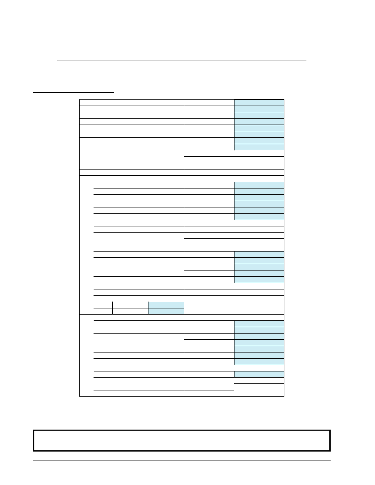
A. SPECIFICATIONS
MAXIMUM CAPACITY (DRY WEIGHT) 75 lb 34.02 kg
TUMBLER DIAMETER 36-1/4” 92.08 cm
TUMBLER DEPTH 36” 91.44 cm
TUMBLER VOLUME 21.50 cu ft 608.81 L
TUMBLER (DRIVE) MOTOR Non-Reversing / Reversing 1 hp / 1/2 hp*0.75 kW / 0.37 kW
BLOWER (FAN) MOTOR Non-Reversing / Reversing — / 1 hp*— / 0.75 kW
DOOR OPENING (DIAMETER) 31-3/8” 79.69 cm
DOOR SILL HEIGHT 28” 71.12 cm
WATER CONNECTION 3/4”-11.5 NH (North America)
3/4” B.S.P.T. (Outside North America)
DRYERS PER 20’/40’ CONTAINER 10 / 20
DRYERS PER 48’/53’ TRUCK 24 / 26
VOLTAGE AVAILABLE 120-575V 1,3ø 2,3,4w 50/60 Hz
APPROXIMATE NET WEIGHT 721 lb 327.04 kg
APPROXIMATE SHIPPING WEIGHT 773 lb 350.63 kg
AIRFLOW 60 Hz 1,000 cfm 28.32 cmm
50 Hz 833 cfm 23.60 cmm
HEAT INPUT 175,000 Btu/hr 44,099 kcal/hr
EXHAUST CONNECTION (DIAMETER) 8” 20.32 cm
COMPRESSED AIR CONNECTION N / A
COMPRESSED AIR VOLUME N / A
INLET PIPE CONNECTION 3/4” F.N.P.T.
3/4” B.S.P.T. (CE and Australia Only)
VOLTAGE AVAILABLE 208-575V 3ø 3,4w 50/60 Hz
APPROXIMATE NET WEIGHT 721 lb 327.04 kg
APPROXIMATE SHIPPING WEIGHT 773 lb 350.63 kg
AIRFLOW 60 Hz 1,000 cfm 28.32 cmm
50 Hz 833 cfm 23.60 cmm
EXHAUST CONNECTION (DIAMETER) 8” 20.32 cm
COMPRESSED AIR CONNECTION N / A
COMPRESSED AIR VOLUME N / A
OVEN SIZE
kW Btu/hr kcal/hr
30 102,400 25,800
VOLTAGE AVAILABLE 120-575V 1,3ø 2,3,4w 50/60 Hz
APPROXIMATE NET WEIGHT 816 lb 370.13 kg
APPROXIMATE SHIPPING WEIGHT 868 lb 393.72 kg
AIRFLOW 60 Hz 1,200 cfm 33.98 cmm
50 Hz 1,000 cfm 28.32 cmm
STEAM CONSUMPTION 275 lb/hr 124.7 kg/hr
OPERATING STEAM PRESSURE 125 psi max 8.62 bar
EXHAUST CONNECTION (DIAMETER) 8” 20.32 cm
COMPRESSED AIR CONNECTION 1/8” F.N.P.T.
COMPRESSED AIR VOLUME 0.75 cfh 0.02 cmh
BOILER HORSEPOWER (NORMAL LOAD) 7.2 Bhp
SUPPLY CONNECTIONS (2) 1-1/4” M.N.P.T.
RETURN CONNECTIONS (2) 1” M.N.P.T.
GAS
Shaded areas are stated in metric equivalents 2/19/09
*Reversing dryers use 3-phase (3ø) motors.
ELECTRICSTEAM

113390-5www.adclaundry.com 7
Specifications (Gas/Electric/Steam)
NOTE: ADCreservestheright tomake changesinspecifications atany timewithoutnotice or
obligation.

8American Dryer Corp. 113390-5
B. COMPONENT IDENTIFICATION
1. Dryer Front View
Illus. No. Description
1Controls
2Control (top access) Door Assembly
3Main Door Assembly
4Lint CompartmentArea (lint screen located behind lint door or left sidewall)
5Data Label and Installation Label (affixed to the upper left side panel area behind the
top control [access] door)

113390-5www.adclaundry.com 9
2. Dryer Rear View
Illus. No. Description
1Heating Unit
2Electric Service Relay Box
3Tumbler Bearing MountAssembly
4Idler Bearing MountAssembly
5Blower Motor Assembly (for reversing models only)
6Leveling Legs (rear)
7Basket (drive) MotorAssembly
8Dryer Exhaust

10 American Dryer Corp. 113390-5
SECTIONIII
INSTALLATION PROCEDURES
Installation should be performed by competent technicians in accordance with local and state codes. In the
absence of these codes, the installation must conform to applicableAmericanNational Standards:ANSI Z223.1-
LATEST EDITION (National Fuel Gas Code) orANSI/NFPA NO. 70-LATEST EDITION (National Electrical
Code) or in Canada, the installation mustconform to applicable Canadian Standards: CAN/CGA-B149.1-M91
(Natural Gas) or CAN/CGA-B149.2-M91 (Liquid Propane [L.P.] Gas) or LATEST EDITION (for General
Installationand Gas Plumbing) orCanadian Electrical Codes Parts1 & 2 CSAC22.1-1990 or LATEST EDITION
(for Electrical Connections).
A. LOCATION REQUIREMENTS
Before installing the dryer, be sure the location conforms to local codes and ordinances. In the absence of such
codesorordinancesthelocationmustconformwiththeNationalFuelGasCodeANSI.Z223.1LATEST EDITION,
orin Canada, the installation must conformto applicable Canadian Standards: CAN/CGA-B149.1-M91 (Natural
Gas) or CAN/CGA-B149.2-M91 (L.P. Gas) or LATEST EDITION (for General Installation and Gas Plumbing).
1. The dryer must be installed on a sound level floor capable of supporting its weight. Carpeting must be
removed from the floor area that the dryer is to rest on.
IMPORTANT: “Thedryermustbeinstalled onnoncombustiblefloors only.”
2. The dryer must not be installed or stored in an area where it will be exposed to water and/or weather.
3. The dryer is for use in noncombustible locations.
4. Provisions for adequate air supply must be provided as noted in this manual (refer to Fresh Air Supply
Requirements in Section D).
5. Clearance provisions must be made from combustible construction as noted in this manual (refer to Dryer
Enclosure Requirements in Section C).
6. Provisions must be made for adequate clearances for servicing and for operation as noted in this manual
(refer to Dryer Enclosure Requirements in Section C).
7. Dryer must be exhausted to the outdoors as noted in this manual (refer to Exhaust Requirements in
Section E).
8. Dryer must be located in an area where correct exhaust venting can be achieved as noted in this manual
(refer to Exhaust Requirements in Section E).
IMPORTANT: Dryershould be located where aminimumamount of exhaustduct will benecessary.
9. The dryer must be installed with a proper exhaust duct connection to the outside.
10. The dryer must be installed with provisions for adequate combustion and make-up air supply.

113390-5www.adclaundry.com 11
CAUTION: Thisdryer produces combustible lintand must be exhausted tothe outdoors. Every six
(6)months,inspectthe exhaustductingandremoveanylintbuild up.
B. UNPACKING / SETTING UP
Remove protective shipping material (i.e., plastic wrap and/or optional shipping box) from dryer.
IMPORTANT: Dryermustbetransported and handledin an uprightposition atALLtimes.
Thedryer can be movedto its final locationwhile still attached tothe skid or withthe skid removed. To unskid the
dryer, locate and remove the four (4) bolts securing the base of the dryer to the wooden skid. Two (2) are at the
rear base (remove the back panel for access), and two (2) are located in the bottom of the lint chamber. To
remove the two (2) bolts located in the lint chamber area, remove the lint door.
To increase bearing life and improve efficiency, the dryer should be tilted slightly to the rear.
The lint coops of ALLdryers aresupported during shipping by abracket. REMOVETHISBRACKETBEFORE
STARTING THE DRYER.
1. Leveling Dryer
The dryer is equipped with four (4) leveling legs, one (1) at each corner of the base. Two (2) are located at
the rear of the dryer base, and two (2) are located in the lint chamber (coop). To increase bearing life and
improve efficiency, the dryer should be tilted slightly to the rear.

12 American Dryer Corp. 113390-5
NOTE: Allowancesmust be made forthe opening ofthecontrol door.
Dryers may be positioned sidewall to sidewall. However, a 1/16” (1.5875 mm) minimum allowance must be
made for the opening and closing of the control door and the lint door. It is suggested that the dryer be positioned
about 2 feet (0.61 meters) away from the nearest obstruction for ease of installation, maintenance, and service
(to be measured from the back guard). Refer to the illustration above for details.
NOTE: Airconsiderations areimportantforproperandefficientoperation.
IMPORTANT: Eventhougha minimumof only12-inches(30.48 cm)isrequired,18-inches(45.72
cm)or more issuggested. The additional clearanceisadvantageous for easeof
installationandservice.
IMPORTANT: Whenfiresprinkler systemsare locatedabove thedryers,a minimumof 18-inches
(45.72cm) above thedryerconsole (module) isrequired. Dryers may be positioned
sidewalltosidewallhowever,a1/16” (1.5875mm)minimumallowanceisrequired
betweendryers(orwall)for easeof installationand maintenance. Allowancesmust
bemade for theopening and closingof the controldoor and thelint door.
C. DRYER ENCLOSURE REQUIREMENTS
Bulkheads and partitions should be made of noncombustible materials and must be located a minimum of
12-inches (30.48 cm), 18-inches (45.72 cm) or more is recommended for ease of installation, maintenance, and
service above the dryer’s outer top, except along the front of the dryer which may be partially closed in if desired.
The clearance between the bulkhead header and the dryer must be a minimum of 4-inches (10.16 cm) and must
not extend more than 4-inches (10.16 cm) to the rear of the front. The bulkhead facing must not be closed in
ALL the way to the top of the dryer. A 1-inch (2.54 cm) clearance is required.

113390-5www.adclaundry.com 13
D. FRESH AIR SUPPLYREQUIREMENTS
Thisappliancemay only be installed inaroom that meets the appropriate ventilationrequirementsspecified in the
nationalinstallationregulations.
When the dryer is operating, it draws in room air, heats it, passes this air through the tumbler, and exhausts it out
of the building. Therefore, the room air must be continually replenished from the outdoors. If the make-up air
is inadequate, drying time and drying efficiency will be adversely affected. Ignition problems and sail switch
“fluttering” problems may result, as well as premature motor failure from overheating.
Air supply (make-up air) must be given careful consideration to assure proper performance of each dryer. An
unrestricted source of air is necessary for each dryer. An airflow of 1,000 cfm (cubic feet per minute), (28.3
cmm [cubic meters per minute]) must be supplied to each dryer. As a general rule, an unrestricted air entrance
from the outdoors (atmosphere) of a minimum of 1-1/2 square feet (0.14 square meters) is required for each
dryer. The dryer must be installed with provisions for adequate combustion and make-up air supply.
To compensate for the use of registers or louvers used over the openings, this make-up airmust beincreased by
approximately thirty-three percent (33%). Make-up air openings should not be located in an area directly near
where exhaust vents exit the building.
It is not necessary to have a separate make-up air opening for each dryer. Common make-up air openings are
acceptable. However, they must be set up in such a manner that the make-up air is distributed equally to ALL
the dryers.
EXAMPLE: For a bank of four (4) dryers, two (2) unrestricted openings measuring 2 feet by 1-1/2 feet (0.61
meters by 0.46 meters), (6 square feet [0.56 square meters]) are acceptable.
Allowances must be made for remote or constricting passageways or where dryers are located at excessive
altitudes or predominantly low pressure areas.
IMPORTANT: Make-upair must be provided froma source freeof drycleaning solvent fumes.
Make-upairthatiscontaminated bydrycleaningsolventfumeswillresultin
irreparabledamage to themotors and otherdryer components.
NOTE: Componentfailuredue todrycleaning solventfumes willVOID THEWARRANTY.

14 American Dryer Corp. 113390-5
E. EXHAUST REQUIREMENTS
1. General Exhaust Ductwork Information
Exhaust ductworkshould be designed and installed by a qualified professional. Improperly sized ductwork
will create excessive back pressure which results in slow drying, increased use of energy, overheating of the
dryer,andshutdown of theburnerbytheairflow (sail) switches,burnerhi-limits,ortumbler hi-heat thermostats.
The dryer must be installed with a proper exhaust duct connection to the outside.
The design of the flue system shall be such that any condensate formed when operating the appliance from
cold shall either be retained and subsequently re-evaporated or discharged.
CAUTION: Thisdryer produces combustible lintand must be exhausted totheoutdoors.
CAUTION: DRYERMUST BEEXHAUSTEDTO THEOUTDOORS.
CAUTION: IMPROPERLY SIZEDORINSTALLEDEXHAUSTDUCTWORKCAN
CREATEAPOTENTIALFIREHAZARD.
IMPORTANT:Itisrecommended that exhaust orbooster fans not be used inthe exhaust ductwork
system.
The ductwork should be laid out in such a way that the ductwork travels as directly as possible to the
outdoors with as few turns as possible. Single or independent dryer venting is recommended.
HorizontalVenting:
When single dryer venting is used, the length of ductwork from the dryer to the outside exhaust outlet must
not exceed 25 feet (7.62 meters). The minimum diameter of this ductwork must be at least 8-inches
(20.32 cm). In the case of multiple (common) dryer venting, the distance from the last dryer to the outside
exhaust outlet must not exceed 15 feet (4.57 meters). The shape of the ductwork is not critical so long as
the minimum cross-sectional area is provided. It is suggested that the use of 90° turns be avoided; use 30°
and/or 45° angles instead. The radius of the elbows should preferably be 1-1/2 times the diameter of the
duct. Including tumbler/dryer elbow connections or elbows used for outside protection from the weather,no
more than two (2) elbows should be used in the exhaust duct run. If more than two (2) elbows are used,
the cross-sectional area of the ductwork must be increased. ALL ductwork should be smooth inside with
noprojections from sheet metal screws orother obstructions, which will collectlint. Whenadding ducts, the
duct to be added should overlap the duct to which it is to be connected. ALL ductwork joints must be taped
toprevent moisture and lint fromescaping into the building. Inspectiondoorsshouldbeinstalled at strategic
points in the exhaust ductwork for periodic inspection and cleaning of lint from the ductwork.
VerticalVenting:
When single dryer venting is used, the length of the ductwork from the dryer to the outside exhaust outlet
must not exceed 15 feet (4.57 meters). The minimum diameter of this ductwork must be at least
8-inches (20.32 cm). In the case of multiple (common) dryer venting, the distance from the last dryer to the
outside exhaust outlet must not exceed 15 feet (4.57 meters). The shape of the ductwork is not so critical
so long as the minimum cross-sectional area is provided. It is suggested that the use of 90° turns be avoided;
use 30° and/or 45° bends instead. The radius of the elbows should preferably be 1-1/2 times the diameter
of the duct. ALL ductwork should be smooth inside with no projections from sheet metal screws or other
obstructions, which will collect lint. When adding ducts, the duct to be added should overlap the duct to
which it is to be connected. ALL ductwork joints must be taped to prevent moisture and lint from escaping
into the building. Inspection doors should be installed at strategic points in the exhaust ductwork for
periodic inspection and cleaning of lint from the ductwork.

113390-5www.adclaundry.com 15
IMPORTANT: Exhaustback pressure measured bya manometer in the exhaustduct must benoless
than 0 and must not exceed 0.7 inches (1.74 mb) of water column (W.C.).
NOTE: Whentheexhaust ductworkpasses througha wall,ceiling,or roofmade ofcombustible
materials, the openingmustbe2-inches(5.08cm) largerthan the duct(all the wayaround).
Theductmustbecenteredwithinthis opening.
a. Outside Ductwork Protection
1) To protect the outside end of the horizontal ductwork from the weather, a 90° elbow bent downward
should be installed where the exhaust exits the building. If the ductwork travels vertically up
through the roof, it should be protected from the weather by using a 180° turn to point the opening
downward. In either case, allow at least twice the diameter of the duct between the duct opening
and the nearest obstruction.
IMPORTANT: DONOTuse screens,louvers,or caps on the outsideopening of the exhaust
ductwork.
2. SingleDryer Venting
Where possible, it is suggested to provide a separate exhaust duct for each dryer. The exhaust duct should
be laid out in such a way that the ductwork travels as directly as possible to the outdoors with as few turns
as possible. It is suggested that the use of 90° turns in the ducting be avoided; use 30° and/or 45° angles
instead. The shape of the exhaust ductwork is not critical so long as the minimum cross section area is
provided.
IMPORTANT: Exhaust backpressure measuredby amanometer inthe exhaustduct mustbenoless
than 0and mustnot exceed 0.7 inches (1.74 mb) of water column.

16 American Dryer Corp. 113390-5
IMPORTANT: Forextended ductwork runs, the cross sectionarea of the ductwork canonlybe
increasedtoan extent. Whentheductwork approachesthemaximumlimitsnoted in
thismanual,aprofessionalheating,venting,and airconditioning(HVAC)firmshould
beconsultedforproper ventinginformation.
ALLductwork shouldbe smooth inside with no projections from sheet metal screws or other obstructions,
which will collect lint. When adding ducts, the duct to be added should overlap the duct to which it is to be
connected. ALL ductwork joints must be taped to prevent moisture and lint from escaping into the
building. Inspection doors should be installed at strategic points in the exhaust ductwork for periodic
inspection and cleaning of lint from the ductwork.
NOTE: Whentheexhaust ductworkpasses througha wall,ceiling,or roofmade ofcombustible
materials, the openingmustbe2-inches(5.08cm) largerthan the duct(all the wayaround).
Theductmustbecenteredwithinthis opening.
a. Outside Ductwork Protection
1) To protect the outside end of the horizontal ductwork from the weather, a 90° elbow bent downward
should be installed where the exhaust exits the building. If the ductwork travels vertically up
through the roof, it should be protected from the weather by using a 180° turn to point the opening
downward. In either case, allow at least twice the diameter of the duct between the duct opening
and the nearest obstruction.
IMPORTANT: DONOTuse screens,louvers,or caps on the outsideopening of the exhaust
ductwork.
Other manuals for AD-758DV
2
Table of contents
Other ADC Dryer manuals
Popular Dryer manuals by other brands

American Dryer Corp.
American Dryer Corp. Phase 6 Microprocessor Controls ML-190HS Service manual

Crosley
Crosley CEDS663SB0 use & care

NANO
NANO D2 user guide

Siemens
Siemens WT43HVP6DN User manual and installation instructions

Bosch
Bosch WTY88898SN Installation and operating instructions

Huebsch
Huebsch ZDE4BR Specifications