Parts and Assembly
This booklet contains operating an maintenance information
for the DIAGNOSTIX™922 series esktop mercurial bloo
pressure instrument. Please rea an retain.
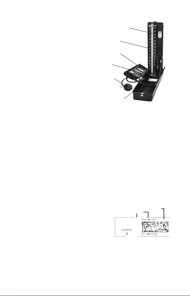
Your DIAGNOSTIX™922 consists of a main unit with 4mm
calibrate unbreakable plastic cartri ge tube, inflation sys-
tem (which inclu es the ADCUFF™nylon cuff with Size
Gui e™ marking system, latex-free inflation bla er, bulb,
an the ADFLOW™ valve), luer connector, an operating in-
structions.
Connectin the Inflation System to Manometer
Remove the re cap which seals the reservoir containing mer-
cury. Attach the free en of reservoir tube securely to air inlet.
Save re safety cap for later use. When transporting mercury
instrument we recommen replacing the re safety cap.
Please note: It is normal for negligible amounts of resi ual
mercury roplets to accumulate aroun the air inlet beneath
the re safety cap uring transportation.
Warning: Before transporting this instrument, mercury must be stored in the tank and the reservoir lock
MUST be switched to the off position to prevent mercury spills.
Operatin Instructions
Your DIAGNOSTIX™ 922 Desktop Mercury Sphygmomanometer incorporates a special safety feature that locks the
mercury within the reservoir uring storage, transport, or maintenance.
To Operate the 922: To release the mercury from the reservoir, move the locking lever to the left. Mercury will flow
up into the plastic cartri ge tube an rest at the “0” mark. If the mercury oesn’t rise within the tube, tilt the entire
unit 45° to the left. If mercury fails to rise, or oesn’t reach the “0” level, have unit service .
To Lock Mercury within the Reservoir: Tilt the entire unit back 45° towar s the reservoir to permit mercury to
flow out of cartri ge tube an into reservoir. When cartri ge tube is completely emptie of ALL mercury (an
while it is still tilte 45°), move locking lever to the right. Mercury shoul be locke within the reservoir uring
maintenance or transport.
PLEASE NOTE: MERCURY SHOULD BE SECURED WITHIN THE RESERVOIR BEFORE CLOSING LID, DURING
TRANSPORT, OR WHEN SERVICING THE CARTRIDGE TUBE, DIAPHRAGMS, OR FILTERS. NEVER DISAS
SEMBLE UNIT UNLESS MERCURY IS FIRST LOCKED WITHIN RESERVOIR.
MEASUREMENT PROCEDURE
1. Patient Position
The patient shoul sit or lie comfortably. The arm shoul be fully sup-
porte on a flat surface at heart level. (If the arm’s position varies, or is
not level with the heart, measurement values obtaine will not be consis-
tent with the patient’s true bloo pressure.) Observer shoul view
manometer in a irect line an at eye level to avoi “parallax error.”
2. Apply the cuff
ADCUFF™ nylon cuffs, with proprietary Size Gui e™marking system,
are specially esigne to promote the precise, accurate etermination
of bloo pressure. In ex an range markings ensure use of the correct cuff size. The artery mark in icates proper cuff
positioning. Place the cuff over the bare upper arm with “artery” mark positione irectly over the brachial artery. The
bottom e ge of the cuff shoul be positione approximately one inch above the antecubital fol . Wrap the en of the
cuff, not containing the bla er, aroun arm snugly an smoothly an engage a hesive strips. To verify a correct fit,
check that the ADCUFF™ nylon cuffs, with proprietary Size Gui e™marking system, are specially esigne to promote
the precise, accurate etermination of bloo pressure. In ex an range markings ensure use of the correct cuff size.
The artery mark in icates proper cuff positioning. Place the cuff over the bare upper arm with “artery” mark positione
irectly over the brachial artery. The bottom e ge of the cuff shoul be positione approximately one inch above the
Select Smaller Cuff
▲
CORRECT
▲
Select Lar er Cuff
▲
Cartrid e Tube
Lockin
Mechanism
Bulb &
Valve
Main Unit
Reservoir
Cuff