manuals.online logo
Brands
  1. Home
  2. •
  3. Brands
  4. •
  5. ADC
  6. •
  7. Network Hardware
  8. •
  9. ADC H2TU-C-202 User manual

ADC H2TU-C-202 User manual

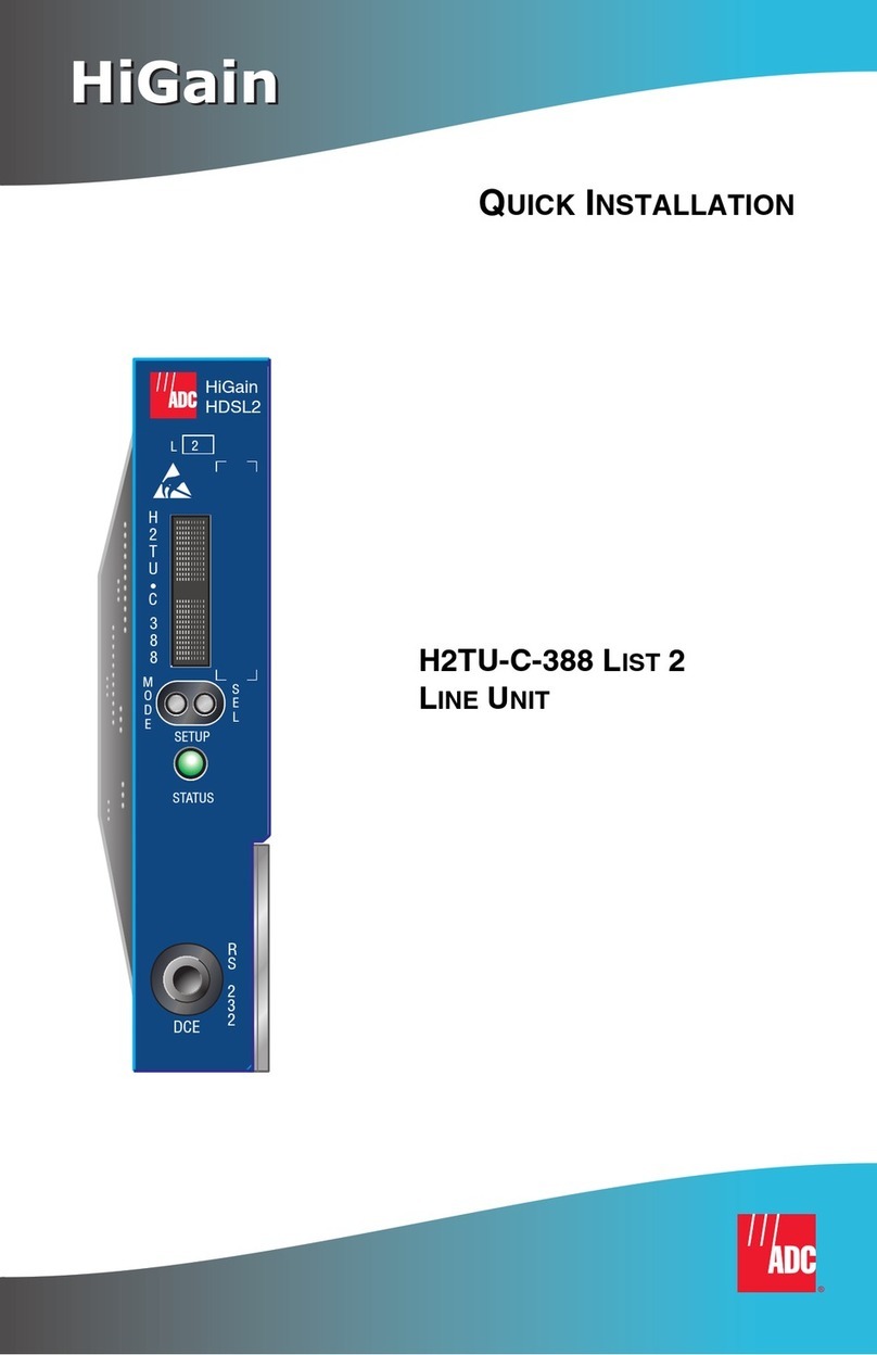
HiGain
HiGain
FCC Class A Compliance
This equipment has been tested and found to comply with the limits for a Class A digital device, pursuant
to Part 15 of the FCC Rules. These limits are designed to provide reasonable protection against harmful
interference when the equipment is operated in a commercial environment. This equipment generates,
uses, and can radiate radio frequency energy and, if not installed and used in accordance with the
instruction manual, may cause harmful interference to radio communications. Operation of this
equipment in a residential area is likely to cause harmful interference in which case the user will be
required to correct the interference at his own expense.
Limited Warranty
Product warranty is determined by your service agreement. Contact your sales representative or
Customer Service for details.
Modifications
Any changes or modifications made to this device that are not expressly approved by ADC DSL
Systems, Inc. voids the user's warranty.
All wiring external to the products should follow the provisions of the current edition of the National
Electrical Code.
Standards Compliance
This equipment has been tested and verified to comply with the applicable sections of the following
standards:
❑GR 63-CORE - Network Equipment-Building System (NEBS) Requirements
❑GR 1089-CORE - Electromagnetic Compatibility and Electrical Safety
❑Binational standard, UL-1950/CSA-C22.2 No. 950-95: Safety of Information Technology
Equipment
Trademark Information
ADC and Soneplex are registered trademarks of ADC Telecommunications, Inc. HiGain is a registered
trademark of PairGain Technologies, Inc. Other product names mentioned in this installation guide are
used for identification purposes only and may be trademarks or registered trademarks of their respective
companies.
Copyright Information
©Copyright 2001 ADC DSL Systems, Inc. All rights reserved. Information contained in this document
is company private to ADC DSL Systems, Inc., and shall not be modified, used, copied, reproduced or
disclosed in whole or in part without the written consent of ADC.
ADC DSL Systems, Inc.
14402 Franklin Avenue
Tustin, CA 92780-7013
Tel: 714.832.9922
Fax: 714.832.9924
Technical Assistance
800.638.0031
714.730.3222
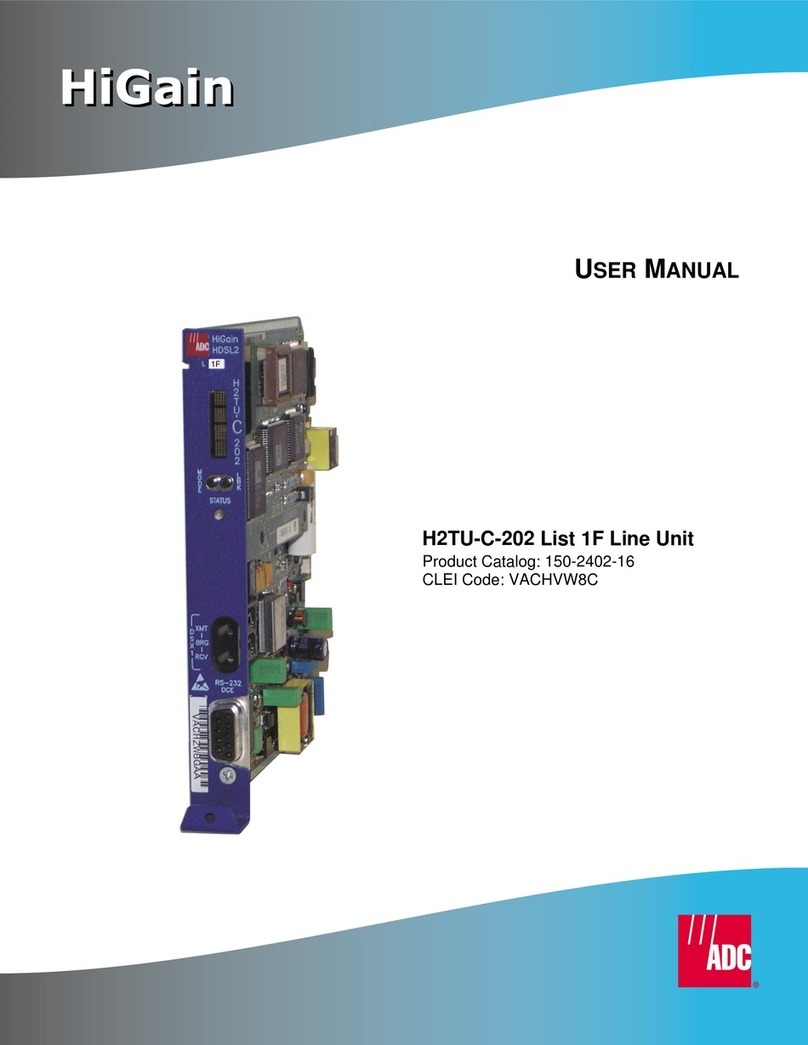
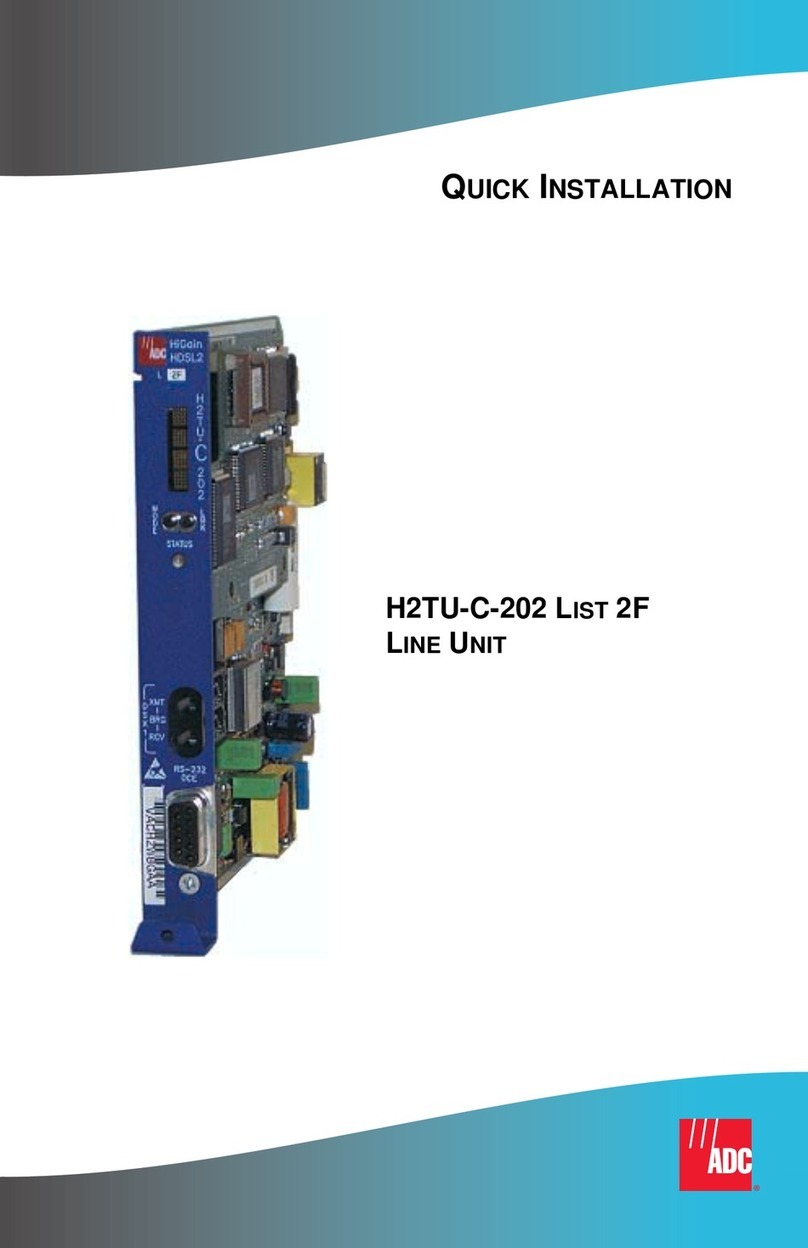
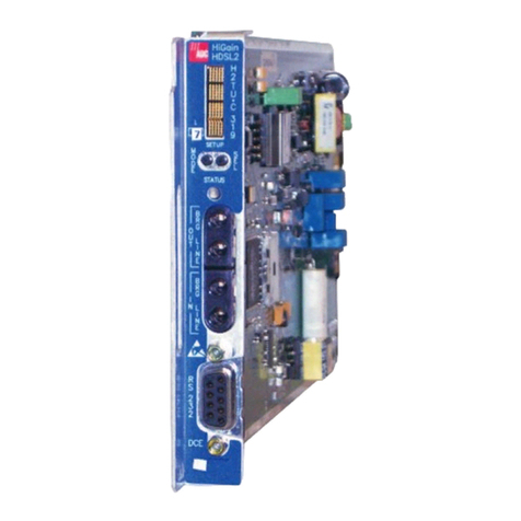
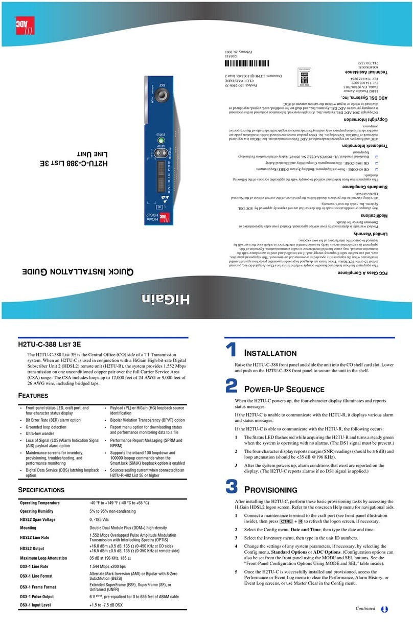
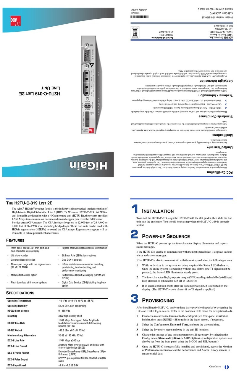
THE H2TU-C-202 LIST 3E
The ADC HiGain
®
product family is the industries first practical implementation of
High-bit-rate Digital SubscriberLine 2(HDSL2).When anH2TU-C-202 lineunit isused
in conjunction with a Higain remote unit (H2TU-R), the system provides 1.552 Mps
transmission on one unconditioned copper pair over the full Carrier Service Area (CSA)
range. The CSA includes loops up to 12,000 feet of 24 AWG or 9,000 feet of 26 AWG
wire, including bridged taps.
FEATURES
SPECIFICATIONS
•Front panel status LED, four-character status
display, and RS-232 port •User-friendly management unit software
interface
•Ultra-low wander •Bit Error Rate (BER) alarm options
•Supports the inband 100 loopdown and
100000 loopup commands when the
SmartJack Loopback (LPBK) option is enabled
•HiGain maintenance screens for inventory,
provisioning, troubleshooting, and
performance monitoring
•Payload (PL) or HiGain (HG) loopback source
identification •Loss of Signal (LOS)/Alarm Indicator Signal
(AIS) payload alarm option
•Grounded loop detection
•Bipolar Violation Transparency (BPVT) options •Report menu option for downloading status
and performance monitoring data to a file
Operating Temperature -40 °F to +149 °F (-40 °C to +65 °C)
Operating Humidity 5% to 95% (non-condensing)
HDSL Span Voltage -140 to ±112 Vdc
Mounting STS, 28-slot high-density shelf or equivalent
HDSL Line Code 784 kbps 2B1Q
HDSL Output +13.5 dBm ±0.5 dB at 135 Ω
Maximum Provisioning Loss 35 dB at 196 kHz, 135 Ω
DS1 Line Rate 1.544 Mbps ±200 bps
DS1 Line Format Alternate Mark Inversion (AMI), Bipolar with 8-Zero Substitution
(B8ZS) or Zero Byte Time Slot Interchange (ZBTSI)
DS1 Frame Format Extended SuperFrame (ESF), SuperFrame (SF), or Unframed (UNFR)
DSX-1 Pulse Output 6 V pk-pk, pre-equalized for 0 to 655 feet of ABAM cable
DSX-1 Input Level +1.5 to -7.5 dB DSX
INSTALLATION
To ensureproper installation ofthe H2TU-C-202,align the unit with the enclosure slot
guides and slide it in until it touches the backplane card-edge connector.
POWER-UP SEQUENCE
When the H2TU-C-202 powers up, the four status LEDs illuminate and report status
messages.
If the H2TU-C-202 is able to communicate with the H2TU-R, the following occurs:
1The LOOP Status LED flashes green while acquiring each device in the system,
and turns a steady green when the entire system is operating without any alarms.
(The DS1 signal must be present.)
2If any alarm conditions exist after the system powers up, these are reported on the
appropriate status LED (see the descriptions of the four status LEDs on the
front-panel illustration inside).
PROVISIONING
After installing the H2TU-C, perform these basic provisioning tasks by accessing the
HiGain HDSL2 logon screen. Refer to the onscreen Help menu for navigational aids.
1Connect a maintenance terminal to the craft port (see front-panel illustration
inside) then press + to refresh the logon screen, if necessary.
2Select the Config menu, Date and Time, then type the date and time.
3Select the Inventory menu, then type in the unit ID numbers.
4Change the settings of any system parameters, if necessary, by selecting the
Config menu, Standard Options or ADC Options.
5Once the H2TU-C-202 is successfully installed and provisioned, access the
Monitor, Performance or Event Log menus to clear the Performance, Alarm
History or Event Log screens, or use Master Clear in the Config menu.
Continued
CTRL R
Þ
L3E
HiGain
HDSL2
D
S
X
1H2TU-C-202 LIST 3E
LINE UNIT
´,#R¶2J¨
1203502
February 28, 2001
Product: 150-2402-35
CLEI: VACJ1KCE
Document: LTPH-QI-1058-02, Issue 2
LOOPBACK TESTING
Initiate loopback testing from the HiGain maintenance menus or use the MODE and SEL
pushbuttons. The inband codes shown below can be sent by a test set.
CONFIGURATION
The H2TU-C-202 List 3E has a configuration switch bank containing eight switches
(located on the printed circuit card). The switches are shown and described below in both
the switch number and switch button figure and the Switch Descriptions table.
For more detailed information about the HiGain HDSL2 screens, provisioning, and
loopback testing, refer to the H2TU-C-202 List 3E technical practice, document number
LTPH-TP-1005-xx. Contact Customer Service to obtain a copy of the practice.
Card handle
List number
Status LEDs
Report the following conditions:
DSX-1 test access jacks
Connect standard test equipment.
Craft port provisioning
To access all system maintenance, provisioning,
and performance screens, connect a standard
9-pin terminal cable between the serial port on a PC
and the H2TU-C craft port.
BRG Provides non-intrusive bridging jack
access to (IN) and from (OUT) the
HDSL2 span at the DSX-1 interface.
Allows monitoring of the T1 payloads.
MaintenanceTerminal Modem Settings
9600 baud
8 data bits
No parity
1 stop bit
Hardware flow control:OFF
Terminal emulation software:VT100
IN
l
BRG
l
OUT
H
2
T
U
*
C
2
0
2
H
D
S
L
2
RS-232
DCE
(CLEI code label
on outside of handle)
L
ALM
LOOP
LBK
DSX
D
S
X
1
ALM LED:
LOOP LED:
LBK LED:
-Solid red when a fuse alarm is present.
-Flashes red once per second while a
local alarm is present.
-Flashes red five times per second while a remote
alarm is present.
-Off when no alarm is present.
-Solid green while all HDSL2 spans are up.
-Flashes green once per second during
a loop acquisition on the span.
-Flashes green five times per second when a
margin or loop attenuation threshold is exceeded.
-Solid yellow when the system is in loopback, NLOC,
or CREM mode.
-Flashes yellow five times per second when the
system is armed.
-Off when the system is not armed and not in
loopback mode.
DSX LED:
-Solid green when DSX-1 signal is present and no
alarm is present.
-Flashes green once per second for BPV, FERR,
UAS, or CRC DSX-1 error.
-Flashes green five times per second when network
side framing or line code provisioning does
not match the DSX-1 signal being received.
-Off when the DSX-1 signal is not present.
3E
Configuration Switch Bank (located on the board) Card-Edge Connector
DSX-1 EQL Equalization
(switches 1-4)
AMI/B8ZS Line code
(switch 5)
LBTO Loopback timeout
(switch 6)
Ft1 Fractional T1
(switch 7)
LCL/SPAN Local/Span Powering
(switch 8)
27
25
23
21
19
17
15
13
11
9
7
3
5
1
DS1 Ring1
DS1 Tip1
Managementbus
Factory use only
Factory use only
HDSL2 Ring
Circuit ground
(-)
(+)
DS1 Ring
DSX-1In
DS1 Tip
HDSL2 Tip
Chassis ground*
Fusealarm
28
26
24
22
20
18
16
14
12
10
8
4
6
2
55
53
51
49
47
45
43
41
39
37
35
32 31
56
54
52
50
48
46
44
42
40
38
36
34
30
33
29
Note: Active pins are highlighted in black.
*Chassis ground may be tied to earth ground per local practice.
DSX-1Out
HDSL2
Span
-48Vdc Local Power
Chassis ground*
Alarm
HiGain
HDSL2
GNLB Loopback Commands
Loopback Inband Code Description
NLOC 1111000 DSX-1 signal is looped back to the network at the H2TU-C.
NREM 1110000 DSX-1 signal is looped back to the network at the H2TU-R.
SMJK 11000 DSX-1 signal is looped back to the network at the H2TU-R SmartJack
module.
CREM 1111110 DS1 signal from customer is looped back to the customer at the H2TU-C.
CLOC 1111100 DS1 signal from customer is looped back to the customer at the H2TU-R.
Loopdown 11100 Deactivates any of the above loopbacks.
Configuration Options Using Maintenance Terminal
Option Code Description (default values in bold)
EQL Sets the DSX-1 Equalizer to 0(0 to 132 ft.), 133 (133 to 265 ft.), 266 (266 to 398 ft.),
399 (399 to 532 ft.), 533 (533 to 655 ft.).
RLBO Sets the H2TU-R line buildout to 0 dB, -7.5 dB, or -15 dB.
LPBK Enables (ENA) or disables (DIS) SmartJack loopback commands.
FT1 Enables (ENA) or disables (DIS) system response to DDS latching loopback commands
for fractional T1 applications.
SPLB xxxx Configures system for generic (GNLB) or special inband loopback commands (A2LB, A3LB, A4LB).
PWRF OFF = disables HDSL2 powering; ON = HDSL2 line voltage is -185 Vdc maximum.
HBER 1E-6 or 1E-7 = alarm activates when the HDSL2 BER alarm threshold exceeds 10-6 or 10-7.
NONE = prevents generation of a system alarm due to BER.
DBER Enables (ENA) or disables (DIS) fixed 24-hour DSX-1 BER alarm threshold.
LBTO Loopback timeout = NONE, 20, 60, 120 minutes.
ALM Enables (ENA) or disables (DIS) alarm indications on pins 22 and 30.
MARG Determines the minimum allowable margin below which a system alarm can occur (5 dB)
0 dB to -15 dB.
DS1 DSX-1 line code = B8ZS, AMI.
CONV H2TU-R frame format conversion = OFF (framing determined by the DS1 FRMG option),
ACON (autodetection of framing and potential frame conversion at the H2TU-R), or FCON
(autodetection of framing and forced frame format conversion at the H2TU-R).
FRMG DS1 frame formatting = AUTO (auto framing mode) or UNFR (unframed mode).
ALMP Enables system to output an alarm pattern: AIS or LOS.
BPVT Enables (ENA) or disables (DIS) Bipolar Violation Transparency.
NLBP Enables the H2TU-R to transmit either AIS or LOS towards CI for any network loopback.
TLOS Enables (ENA) or disables (DIS) a logic loopback at the H2TU-R when an LOS occurs at its
DS1 input.
LATT Loop Attenuation Threshold (0 - 40 dB). Default = 32 dB.
RTPV Enables (ENA) or disables (DIS) remote provisioning.
PRM OFF = no enhanced Performance Report Messaging; SPRM = Supplemental PRM;
NPRM = Network PRM; S + N = SPRM + NPRM.
NAIS If ALMP is set to AIS, NAIS option specifies which pattern is sent to the network when a
remote LOS or AIS occurs. CI = AIS-CI sent to the network; AIS = AIS sent to the network.
ROVR Enables (ENA) or disables (DIS) conversion of an ESF DS1 payload from the network with
an embedded RAI pattern to an SF-RAI pattern towards the CI at the H2TU-R. CONV
option must be set to FCON or ACON.
RACI Enables (ENA) or disables (DIS) conversion of a DS1 SF-RAI signal received by the H2TU-R
to an SF-RAI-CI signal towards the network.
Network
Customer
Premises
H2TU-C H2TU-R
TLOS*
NLOC CREM CLOC
1111000 NREM
1110000 1111100
1111110
11000
SMJK
When enabled,TLOS is an automatic loopback
that occurs with an LOS at the remote DS1 input.
*
DS1DSX-1
The H2TU-C-202 List 3E does not have a display or MODE and
SEL pushbuttons. Set the switches on the on-board switch
bank or accessthe maintenance terminal screens through the
craft port to make configuration changes.
Switch Descriptions (default values in bold)
Leftmost Switch Position Options Switch
Number Rightmost Switch Position Options
Sets the equalizer to 133 to 265 feet 1 (a)
(a) Only one of the DSX-1 line equalization switches (1 - 4) can be selected at a time. If more than one switch
is enabled, the lowest value setting has priority.
0
Sets the equalizer to 266 to 398 feet 2 (a) 0
Sets the equalizer to 399 to 532 feet 3(a) 0
Sets the equalizer to 533 to 655 feet 4 (a) 0
Selects the DSX-1 line code Alternate Mark
Inversion (AMI) 5Selects Bipolar with 8-Zero Substitution
(B8ZS)
Enables the Loopback Timeout (LBTO) for
120 minutes 6Disables LBTO
Enables Fractional T1 (FT1) loopback
capability 7Disables FT1 loopback capability
Configures the system for Line powering 8Configures the system for Span powering
To comply with the intrabuilding wiring requirements of
GR-1089 CORE, Section 4.5.9, the shields of the ABAM-type
cables that connect the H2TU-C-202 DSX-1 output ports to the
cross-connect panel must be grounded at both ends.
Other manuals for H2TU-C-202

10

This manual suits for next models

2

Other ADC Network Hardware manuals

ADC HiGain HXU-358 User manual

ADC

ADC HiGain HXU-358 User manual

ADC HiGain H2TU-C-319 List 4E Original operating instructions

ADC

ADC HiGain H2TU-C-319 List 4E Original operating instructions

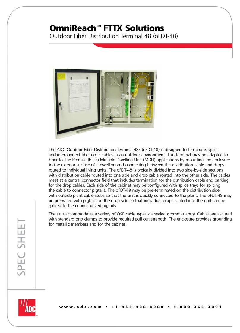
ADC OmniReach MDU Rapid Fiber System User manual

ADC

ADC OmniReach MDU Rapid Fiber System User manual

ADC High Density Position Panel LSX 288 User manual

ADC

ADC High Density Position Panel LSX 288 User manual

ADC OmniReach oFDT-48 User manual

ADC

ADC OmniReach oFDT-48 User manual

ADC HiGain HLU-388 List 5 Original operating instructions

ADC

ADC HiGain HLU-388 List 5 Original operating instructions

ADC HRE-204 List 1 User manual

ADC

ADC HRE-204 List 1 User manual

ADC HiGain HRU-402 User manual

ADC

ADC HiGain HRU-402 User manual

ADC HiGain HMS-318 List 3 User manual

ADC

ADC HiGain HMS-318 List 3 User manual

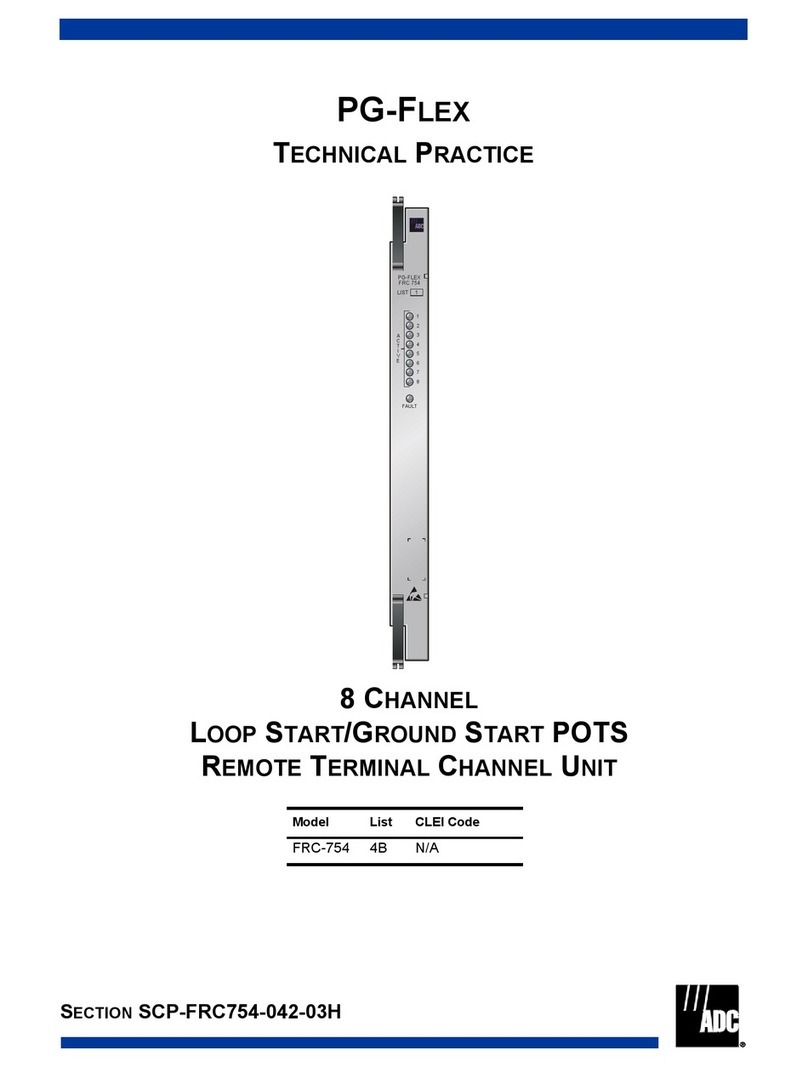
ADC H2TU-C-202 User manual

ADC

ADC H2TU-C-202 User manual

ADC Soneplex P-61-743 User manual

ADC

ADC Soneplex P-61-743 User manual

ADC H2TU-C-202 Original operating instructions

ADC

ADC H2TU-C-202 Original operating instructions

ADC HRM-238 L1 User manual

ADC

ADC HRM-238 L1 User manual

ADC Gas Discharge Tube ComProtect System manual

ADC

ADC Gas Discharge Tube ComProtect System manual

ADC H2TU-C-388 HiGain User manual

ADC

ADC H2TU-C-388 HiGain User manual

ADC Campus-RS Remote User manual

ADC

ADC Campus-RS Remote User manual

ADC FPL Series User manual

ADC

ADC FPL Series User manual

ADC H4TU-C-319 List 1 Line Unit User manual

ADC

ADC H4TU-C-319 List 1 Line Unit User manual

ADC HiGain HDSL2 User manual

ADC

ADC HiGain HDSL2 User manual

ADC Campus-RS REX2 User manual

ADC

ADC Campus-RS REX2 User manual

ADC HiGain H2TU-C-319 List 4E User manual

ADC

ADC HiGain H2TU-C-319 List 4E User manual

ADC RF Signal Management SignalOn Series User manual

ADC

ADC RF Signal Management SignalOn Series User manual

ADC WiMAX Single-sector Base Station WMX 3000 User manual

ADC

ADC WiMAX Single-sector Base Station WMX 3000 User manual

ADC HiGain HLU-231 List 8F Original operating instructions

ADC

ADC HiGain HLU-231 List 8F Original operating instructions

Popular Network Hardware manuals by other brands

Advantech FWA-3260 user manual

Advantech

Advantech FWA-3260 user manual

Belden DCX quick start guide

Belden

Belden DCX quick start guide

ENDEVCO 4418 instruction manual

ENDEVCO

ENDEVCO 4418 instruction manual

LevelOne NVR-0432 user manual

LevelOne

LevelOne NVR-0432 user manual

Proscend 708E Series user manual

Proscend

Proscend 708E Series user manual

MikroTik RBLDF-5nD quick guide

MikroTik

MikroTik RBLDF-5nD quick guide

Avigilon Premium NVR5 Series installation guide

Avigilon

Avigilon Premium NVR5 Series installation guide

ADTRAN DS3 NIU3 PM Installation and maintenance practice

ADTRAN

ADTRAN DS3 NIU3 PM Installation and maintenance practice

OriginGPS OriginIoT user guide

OriginGPS

OriginGPS OriginIoT user guide

Cisco Nexus 93600CD-GX Hardware installation guide

Cisco

Cisco Nexus 93600CD-GX Hardware installation guide

Com-Power LI-1100C instruction manual

Com-Power

Com-Power LI-1100C instruction manual

D-Link ShareCenter Pulse DNS-320 Quick install guide

D-Link

D-Link ShareCenter Pulse DNS-320 Quick install guide

Maxx Wave MW-1404 Quick install guide

Maxx Wave

Maxx Wave MW-1404 Quick install guide

Bay Networks BayStack 400-ST1 installation manual

Bay Networks

Bay Networks BayStack 400-ST1 installation manual

ATV DR-6232H-8TB Operation manual

ATV

ATV DR-6232H-8TB Operation manual

Juniper PTX10004 Hardware guide

Juniper

Juniper PTX10004 Hardware guide

SunEyes Mini NVR Quick start manual

SunEyes

SunEyes Mini NVR Quick start manual

Castelle Premier user guide

Castelle

Castelle Premier user guide

manuals.online logo
manuals.online logoBrands
  • About & Mission
  • Contact us
  • Privacy Policy
  • Terms and Conditions

Copyright 2025 Manuals.Online. All Rights Reserved.