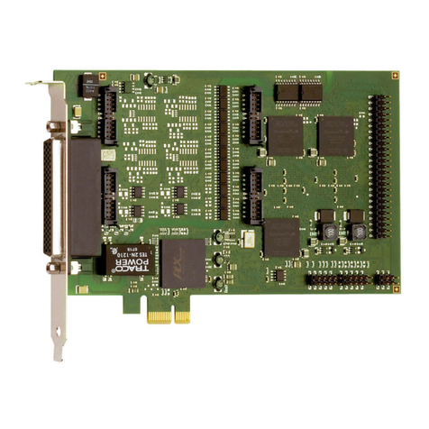
Addi-Data APCI-3701 Parts list manual

Solutions for industrial automation and measurement
___________________________________________________________________________________________________
ADDI-DATA GmbH • Dieselstr. 3 • D-77833 Ottersweier • Phone +49(0)72 23 / 94 93-0 • Fax: +49(0)72 23 / 94 93-92
Important information
1. Software update SET3701
2. Diagnostic function
3. Change position of Pin 1
4.NewcableFB3702

Solutions for industrial automation and measurement
___________________________________________________________________________________________________
ADDI-DATA GmbH • Dieselstr. 3 • D-77833 Ottersweier • Phone +49(0)72 23 / 94 93-0 • Fax: +49(0)72 23 / 94 93-92
E-Mail: [email protected]
Because of the migration to RoHS-compliant products the board APCI-3701 has
been revised.
• Internet: www.addi-data.com
Thus, do observe the following changes:
The photo shows a
new APCI-3701.
1. Software update SET3701
WICHTIG!
i Because of the migration to RoHS-compliant
ADDI-DATA products, the board APCI-3701 has been
revised. Thus, it is necessary to update the software!
Please observe that you must use the calibration and update tool SET3701 from
version 3030-1006 for the new board. Please find the current version of SET3701 on
the delivered CD.
If you replace an old board by a new APCI-3701:
Uninstall the old version of SET3701 and install the new version of SET3701.
2. Diagnostic function
After the calibration of the board, it is possible to detect with the Primary Open Circuit
Test if no transducer is connected.

Solutions for industrial automation and measurement
___________________________________________________________________________________________________
ADDI-DATA GmbH • Dieselstr. 3 • D-77833 Ottersweier • Phone +49(0)72 23 / 94 93-0 • Fax: +49(0)72 23 / 94 93-92
E-Mail: [email protected]
3. Position Pin 1 of the connector ST3
Old: New:
APCI-3701 after the change to
RoHS-compliant
APCI-3701 before the change to
RoHS-compliant
4. New cable FB3702
The ribbon cable FB3702 replaces the cable FB3701.
Connection new cable FB3702
Connection FB3701:
Should you still have a FB3701 cable and want to use it, please do observe also the
new position of Pin 1 and that the red cable line must be connected to Pin 1 (right
side below). Therefore you must turn the cable. Thus, we recommend you to use the
new cable FB3702 – for an easy connection.
• Internet: www.addi-data.com

DIN EN ISO 9001:2000
certified
Edition: 03.05 - 11/2006
A
DDI-DATA GmbH
Dieselstraße 3
D-77833 OTTERSWEIER
Technical support:
+49 (0)7223 / 9493 – 0
Technical description
APCI-3701
Length measurement board,
optically isolated, 16-bit

2
Product information
This manual contains the technical installation and important instructions for correct
commissioning and usage, as well as production information according to the current status
before printing.
The content of this manual and the technical product data may be changed without prior
notice.
ADDI-DATA GmbH reserves the right to make changes to the technical data and the
materials included herein.
Warranty and liability
The user is not permitted to make changes to the product beyond the intended use, or to
interfere with the product in any other way.
ADDI-DATA shall not be liable for obvious printing and phrasing errors. In addition, ADDI
DATA, if legally permissible, shall not be liable for personal injury or damage to materials
caused by improper installation and/or commissioning of the board by the user or improper
use, for example, if the board is operated despite faulty safety and protection devices, or if
notes in the operating instructions regarding transport, storage, installation, commissioning,
operation, thresholds, etc. are not taken into consideration. Liability is further excluded if the
operator changes the board or the source code files without authorisation and/or if the
operator is guilty of not monitoring the permanent operational capability of working parts and
this has led to damage.
Copyright
This manual, which is intended for the operator and its staff only, is protected by copyright.
Duplication of the information contained in the operating instructions and of any other
product information, or disclosure of this information for use by third parties, is not permitted,
unless this right has been granted by the product licence issued. Non-compliance with this
could lead to civil and criminal proceedings.
ADDI-DATA software product licence
Please read this licence carefully before using the standard software. The customer is only
granted the right to use this software if he/she agrees with the conditions of this licence.
The software must only be used to set up the ADDI-DATA boards.
Reproduction of the software is forbidden (except for back-up and for exchange of faulty data
carriers). Disassembly, decompilation, decryption and reverse engineering of the software are
forbidden. This licence and the software may be transferred to a third party if this party has
acquired a board by purchase, has agreed to all the conditions in this licence contract and the
original owner does not keep any copies of the software.
Trademarks
-ADDI-DATA is a registered trademark of ADDI-DATA GmbH.
-Turbo Pascal, Delphi, Borland C, Borland C++ are registered trademarks of Borland
Insight Company.
-Microsoft C, Visual C++, Windows XP, 98, Windows 2000, Windows 95, Windows NT,
EmbeddedNT and MS DOS are registered trademarks of Microsoft Corporation.
-LabVIEW, LabWindows/CVI, DasyLab, Diadem are registered trademarks of National
Instruments Corp.
-CompactPCI is a registered trademark of PCI Industrial Computer Manufacturers Group.
-VxWorks is a registered trademark of Wind River Systems Inc.

3
WARNING
In case of wrong uses and if the board is not used for
the purpose it is intended:
♦people may be injured,
♦the board, PC and peripheral may be destroyed,
♦the environment may be polluted
♦Protect yourself, the others and the environment!
♦Read carefully the safety precautions (yellow leaflet).

If this leaflet is not with the documentation, please contact us and
ask for it.
♦Observe the instructions of the manual.
Make sure that you do not forget or skip any step. We are not liable
for damages resulting from a wrong use of the board.
♦Used symbols:
i IMPORTANT!
designates hints and other useful information.
WARNING!
It designates a possibly dangerous situation.
If the instructions are ignored the board, PC and/or peripheral may
be destroyed.

Definition of application APCI-3701
4
1DEFINITION OF APPLICATION ......................................8
1.1 Intended use ........................................................................... 8
1.2 Limits of use............................................................................. 9
1.3 Usage restrictions.................................................................... 9
2USER.........................................................................10
2.1 Qualification ......................................................................... 10
2.2 Personal protection............................................................... 10
3HANDLING OF THE BOARD.........................................11
4TECHNICAL DATA ......................................................12
4.1 Electromagnetic compatibility (EMC) ................................... 12
4.2 Physical set-up of the board................................................. 12
4.3 Versions................................................................................. 13
4.4 Limit values of the standard version ..................................... 13
4.4.1 Sinus generator............................................................................14
4.4.2 Analog inputs...............................................................................15
4.4.3 Digital outputs..............................................................................15
4.4.4 Digital inputs.................................................................................15
4.5 Technical data of the accessories........................................ 16
4.5.1 Connection boxes and cables of the standard versions .............16
Connection box...........................................................................16
Cable specifications....................................................................16
4.6 Supported transducers.......................................................... 17
4.7 Component scheme.............................................................. 18
5INSTALLATION OF THE BOARD....................................19
5.1 Opening the PC..................................................................... 19
5.2 Selecting a free slot .............................................................. 19
5.3 Closing the PC ...................................................................... 21
6ACCESSORIES...........................................................22
6.1 Cables................................................................................... 22
6.1.1 Standard cables: ST3701, ST3701-5 und ST3701-10.....................24
6.1.2 1-channel-cables: ST3701-1-HB und ST3701-1-LVDT....................24
6.2 Connection boxes................................................................. 25
6.3 Connection examples........................................................... 25
Connection: 1-channel version with a transducer.......................25

APCI-3701 Definition of application
5
7SOFTWARE ................................................................26
7.1 Board registration ................................................................. 27
7.1.1 Installation of a new board..........................................................27
ADDevice Manager.....................................................................28
7.1.2 Changing the registration of a board..........................................29
Description of the ADDIREG program..........................................29
7.2 Questions and software downloads on the web................... 32
8CONNECTING THE PERIPHERAL..................................33
8.1 Connector pin assignment.................................................... 33
8.1.1 50-pin SUB-D male front connector ST1.......................................33
8.1.2 40-pin male connector ST3.........................................................34
8.2 Connection of inductive transducers.................................... 35
8.2.1 Connection of half-bridge transducers .......................................35
8.2.2 Connection of LVDT transducers (Series-opposed)......................35
8.2.3 Connection of Mahr transducers.................................................36
8.3 Connection of the digital inputs and outputs....................... 37
8.4 Connection to screw terminal panels/boxes........................ 38
9FUNCTIONS OF THE BOARD .......................................39
9.1 Block diagram....................................................................... 39
9.2 Acquisition principle............................................................. 39
9.2.1 Board calibration.........................................................................40
9.2.2 Board settings..............................................................................40
9.3 Primary circuit....................................................................... 41
9.3.1 Sinus generator............................................................................41
Synchronising...............................................................................41
9.3.2 Power buffer ................................................................................41
9.4 Secondary circuit.................................................................. 42
9.4.1 Measurement of the supply signal ..............................................42
9.4.2 A/D converter...............................................................................42
9.5 Transducer principle............................................................. 43
9.5.1 Half-bridge transducer.................................................................43
9.5.2 LVDT transducer (Series-opposed) ...............................................44
9.5.3 Settings of the transducer............................................................44
9.6 Possible acquisitions ............................................................ 45
Delay...........................................................................................45
9.7 Diagnostic............................................................................. 47
9.7.1 Short circuit..................................................................................47
9.7.2 Line break....................................................................................47
9.8 Interrupt................................................................................. 47
9.9 Timer...................................................................................... 47

Definition of application APCI-3701
6
10 STANDARD SOFTWARE...............................................48
10.1 Software functions................................................................. 48
10.2 Software samples.................................................................. 51
11 SET3701: CALIBRATION AND UPDATE TOOL ...............52
11.1 Introduction........................................................................... 52
11.2 Program start ........................................................................ 52
11.3 Board information ................................................................. 53
11.4 Transducer database............................................................ 53
11.4.1 Menu transducer database.........................................................54
11.4.2 ADDI-DATA GmbH transducer database......................................55
11.4.3 User transducer database ...........................................................55
11.4.4 New transducer type definition....................................................55
11.5 Board database.................................................................... 58
11.5.1 “Board database” menu..............................................................59
11.5.2 Copy a new transducer type into the board database...............59
11.5.3 Copy a transducer type via the command.................................59
11.5.4 Copy a transducer type through drag & drop.............................60
11.5.5 Save the board database...........................................................61
11.6 Transducer calibration.......................................................... 61
11.6.1 Transducer calibration menu.......................................................63
11.6.2 Calibration...................................................................................63
11.7 Transducer monitoring.......................................................... 66
11.7.1 Transducer monitoring menu.......................................................67
11.7.2 Acquisition....................................................................................67
11.8 Firmware update................................................................... 68
12 GLOSSARY ................................................................70
13 INDEX .......................................................................73

APCI-3701 Definition of application
7
Figures
Fig. 3-1: Correct handling........................................................................11
Fig. 4-1: Required slots.............................................................................13
Fig. 4-3: Component scheme.................................................................18
Fig. 5-1: PCI slot types ..............................................................................19
Fig. 5-2: Inserting the board.....................................................................20
Fig. 5-3: Fastening the board at the back cover .....................................21
Fig. 6-1: Connection of a ST3701-1-x with board and transducer............25
Fig. 7-1: New inserted board (example)...................................................27
Fig. 7-2: ADDevice Manager (example) ..................................................28
Fig. 7-3: ADDIREG registration program (example)...................................29
Fig. 8-1: Pin assignment: APCI-3701-16....................................................33
Fig. 8-2: Pin assignment: APCI-3701-8......................................................34
Fig. 8-3: Pin assignment: 40-pin connector to 37-pin SUB-D bracket ......34
Fig. 8-4: Connection of half-bridge transducers ......................................35
Fig. 8-5: Connection of LVDT transducers (Series-opposed).....................35
Fig. 8-6: Digital inputs...............................................................................37
Fig. 8-7: Digital outputs.............................................................................37
Fig. 8-8: Connection to screw terminal panels/boxes..............................38
Fig. 9-1: Block diagram of the APCI-3701 ................................................39
Fig. 9-2: Acquisition principle of the APCI-3701........................................39
Fig. 9-3: Half-bridge transducer ...............................................................43
Fig. 9-4: LVDT transducer (Series-opposed) ..............................................44
Fig. 9-5: Possible acquisitions: Single start enable....................................46
Fig. 9-6: Possible acquisitions: single software/hardware trigger...............46
Fig. 9-7: Possible acquisitions: sequence start enable.............................46
Fig. 9-8: Possible acquisitions: m/n sequences with hardware/software
trigger......................................................................................46
Fig. 11-1: Window „Transducer database“...............................................54
Fig. 11-2: Menu transducer database.....................................................54
Fig. 11-3: Example: Definition of a new type............................................56
Fig. 11-4: Display: New transducer type...................................................56
Fig. 11-5: Save a new type ......................................................................57
Fig. 11-6: Window„Board database“........................................................58
Fig. 11-7: „Transducer calibration“ window..............................................62
Fig. 11-8: Transducer calibration menu ...................................................63
Fig. 11-9: Window „Transducer calibration“..............................................66
Fig. 11-10: Monitoring menu....................................................................67
Fig. 11-11: Window „Firmware update“....................................................69
Tables
Table 4-1: Available frequency values for the sinus generator.................14
Table 7-1: Compliance of the Mahr transducers.....................................36
Table 8-1: Timer time intervals..................................................................47
Table 9-1: Supported software functions..................................................48
Table 9-2: Supported software samples...................................................51

Definition of application APCI-3701
8
1DEFINITION OF APPLICATION
1.1 Intended use
The board APCI-3701 is the interface between an industrial process and a
personal computer (PC).
The board APCI-3701 must be inserted in a PC with PCI 3.3 V/5V / 32-bit/64-bit
slots, which is used as electrical equipment for measurement, control and
laboratory use as defined in the norm IEC 61010-1.
The PC is to comply with the norm IEC 61326 for measurement, control and
laboratory use and with the specifications for EMC protection.
Products complying with these specifications bear the CE mark.
Data exchange between the APCI-3701 board and the peripheral is to occur
through a shielded cable. This cable must be connected to the 50-pin SUB-D male
connector of the APCI-3701 board. The board is fitted with a sinus generator and
has up to 16 analog inputs for connecting up to 16 inductive displacement
transducers exclusively.
The PX371 screw terminal panel allows the connection of the analog signals with
the ST370 shielded cable.
The use of the board APCI-3701 in combination with external screw terminal
panels is to occur in a closed switch cabinet.
The installation is to be effected competently. Check the shielding capacity of
the PC housing and of the cable prior to putting the device into operation.
The connection with our standard cable ST3701 complies with the following
specifications:
-metallized plastic hoods
-shielded cable
-cable shield folded back and firmly screwed to the connector housing.
The use of the board according to its intended purpose includes observing all
advises given in this manual and in the safety leaflet.
Uses beyond these specifications are not allowed. The manufacturer is not liable
for any damages which would result from the non-observance of this clause.

APCI-3701 Definition of application
9
1.2 Limits of use
The APCI-3701 board is not to be used as safety related part for securing
emergency stop functions.
The emergency stop functions are to be secured separately.
This securing must not be influenced by the board or the PC.
The use of the board in a PC could change the PC features regarding noise
emission and immunity. Increased noise emission or decreased noise immunity
could result in the system not being conform anymore.
The installation of the board APCI-3701 in sites lying under risk of explosion
is excluded.
1.3 Usage restrictions
The APCI-3701 board must not to be used as safety related part for securing
emergency stop functions.
The APCI-3701 board must not be used in potentially explosive atmospheres.
Make sure that the board remains in its protective blister pack until it is used.
Do not remove or alter the identification numbers of the board.
If you do, the guarantee expires.

User APCI-3701
10
2USER
2.1 Qualification
Only persons trained in electronics are entitled to perform the following works:
-installation
-use,
-maintenance.
2.2 Personal protection
Consider the country-specific regulations about:
-the prevention of accidents
-electrical and mechanical installations
-radio interference suppression.

APCI-3701 Handling of the board
11
3HANDLING OF THE BOARD
Fig. 3-1: Correct handling

Technical data APCI-3701
12
4TECHNICAL DATA
4.1 Electromagnetic compatibility (EMC)
The board has been subjected to EMC tests in an accredited laboratory. The board
complies with the limit values set by the norms IEC 61326 as follows:
True value Set value
ESD (Discharge by contact/air)................. 4/8 kV 4/8 kV
Fields ......................................................... 10 V/m 10 V/m
Burst .......................................................... 4 kV 2 kV
Conducted radio interferences .................. 10 V 10 V
4.2 Physical set-up of the board
The board is assembled on a 4-layer printed circuit card.
Dimensions:
138 mm
107 mm
Weight: ..................................................... approx. 160 g
Installation in: ........................................... 32/64-bit PCI slot 5 V or 3.3 V
Connection to the peripheral: ................... 50-pin SUB-D male connector
Accessories1:
for the standard version APCI-3701
Cables:
Standard cable: ......................................... ST3701, 2 m; max. length: 10 m
Ribbon cable: ............................................ FB3702 (connection of the dig. I/O)
Connection boxes/Screw terminal panel:
for LVDT transducers: ............................. PX3701LVDT-8 or PX3701LVDT-16
for half-bridge transducers: ...................... PX3701HB-8 or PX3701HB-16
Screw terminal panel: ............................... PX 901-ZG for the digital I/O
1Not included in the standard delivery.

APCI-3701 Technical data
13
4.3 Versions
The board APCI-3701 is available in the following versions:
Standard Version Number of connected
transducers
Number of connected
digital I/O
APCI-3701-16 16 8 inputs and 8 outputs
APCI-3701-8 8 8 inputs and 8 outputs
Please observe:
If you use LVDT transducers ≥±1 mm, please use the version
APCI-3701-LVDT+.
4.4 Limit values of the standard version
Max. altitude: ............................................ 2000 m
Operating temperature: .............................. 0 to 60°C
Storage temperature: ................................. -25 to 70°C
Relative humidity: ..................................... 30% to 99% non condensing
Minimum PC requirements:
PCI BIOS from Version 1.0
Bus speed: ................................................. < 33 MHz
Operating system: ..................................... Windows NT, 98, 2000, XP
Slot: ........................................................... PCI 5 V or PCI 3.3 V, 32-bit
+ 1 slot opening for connecting
the digital I/O
Fig. 4-1: Required slots1
PCI bus interface
Bus speed: ................................................. < 33 MHz
Data access: ............................................... 32-bit
Decoding: .................................................. in 32-byte I/O address range
of the PC
in 256-byte memory range
of the PC
1Since the switching to RoHS-compliant products, the position of Pin 1 changed (see figure)

Technical data APCI-3701
14
Energy requirements:
- Operating voltage of the PC: .................. 5 V ±5%
- Current consumption (without load): ..... typ. see table ±10%
APCI-3701-8 APCI-3701-16
+ 5 V from PC 0.48 A 0.58 A
WARNING !
The cooling components and the DC/DC connector can warm
up during the board operation.
♦Install the board in the PC so that cooling air can flow easily between the
different inserted boards.
♦Before removing the board from the PC, wait until it sufficiently cooled
down.
4.4.1 Sinus generator
Output signal: ........................................... sinus
Possible frequency values
Table 4-1: Available frequency values for the sinus generator
1.993 kHz 9.765 kHz
3.005 kHz 10.851 kHz
3.986 kHz 12.207 kHz
4.883 kHz 13.021 kHz
6.104 kHz 13.951 kHz
6.975 kHz 16.276 kHz
8.138 kHz 19.531 kHz
Edge frequency of the high-pass filter (-3 dB): 230 Hz
Output voltage: ......................................... can be set between 0.707 Vrms
and 3.5 Vrms
Output current: .......................................... ±260 mA max.
Offset voltage: .......................................... ±1 mV typ.
Harmonic distortion: ................................. 0.75 % typ.
(Duty Cycle adjusted to 50%)
Duty cycle: ................................................ 50 % typ.

APCI-3701 Technical data
15
4.4.2 Analog inputs
Number: .................................................... 8 to 16
Input type: ................................................. single-ended
Coupling: ................................................... AC
Edge frequency of the
high-pass filter (-3 dB):.............................. 500 Hz
Edge frequency of the
low pass filter (-3 dB): ............................... 32 kHz
Maximum input voltage: ........................... 0.916 Vrms typ.
Input capacity: ........................................... 54 pF typ.
Input resistance: ........................................ can be set up to 200 kΩmax.
A-D converter
Resolution: ................................................ 16-bit
Precision: ................................................... 13-bit
Digital coding: ........................................... 2nd complement
Dynamic range: ......................................... 98 dB
Digital filter
Pass band ripple: ....................................... from -0.09 dB to 0 dB
Stop band: ................................................. 64.1 kHz min.
Stop band attenuation: ............................... -48.4 dB min.
High-pass filter
Edge frequency (-3dB): ............................. 3.7 Hz typ.
Edge frequency (-0,1 dB): ......................... 24.2 Hz typ.
Pass band ripple: ....................................... 0.09 dB max.
4.4.3 Digital outputs
Number: .................................................... 8
Output type: ............................................... Open Collector
Nominal voltage: ....................................... 24 V
Output range: ............................................. 5-30 V
Switching current: ..................................... 50 mA
Optical isolation: ....................................... 1000 V
4.4.4 Digital inputs
Number: .................................................... 8
Input type: ................................................. 24 V
Nominal voltage: ....................................... 24 V
Input range: ............................................... 0-30 V
Switching current: ..................................... 6 mA at nominal voltage
Logical input levels (standard): ................. UHmax.: 30 V
UH min.: 19 V
UL max.: 14 V
ULmin.: 0 V
Optical isolation: ....................................... 1000 V
Input frequency of trigger input 0: ............ 1 MHz
Input frequency of the inputs 1 to 7: ......... 5 kHz

Technical data APCI-3701
16
4.5 Technical data of the accessories
4.5.1 Connection boxes and cables of the standard versions
Version Number of connected transducers Connection cable
PX3701HB-16 16 half-bridge transducers ST3701-16
PX3701HB-8 8 half-bridge transducers ST3701-8
PX3701LVDT-16 16 LVDT transducers ST3701-16
PX3701LVDT-8 8 LVDT transducers ST3701-8
Connection box
Housing: ................................................... Aluminium die-cast
The signal connections can be labelled
Protection: ................................................. protecting cap for flange socket,
dustproof, IP54
Transducer connection: ............................. 8 or 16 x 5-pin flange socket
DIN 45322
See Connection of inductive transducers
Connector: ................................................ 50-pin SUB-D female connector
for connecting the cable ST3701
Dimensions (L x W x H):
PX 3701-8: ................................................ 80 x 57 x 120 mm
PX 3701-16: .............................................. 80 x 57 x 250 mm
Fastening : ................................................. through 2 mounting points
within the enclosure bottom
Temperature range: ................................... 0 to 60 °C
Cable specifications
Cable length: ............................................. 2 m, 5 m or 10 m
Connectors: ............................................... 50-pin SUB-D female connector (board)
to 50-pin SUB-D male connector
(connection box)
Shield: ....................................................... twisted-pair leads with common shield

APCI-3701 Technical data
17
4.6 Supported transducers
The transducer type and manufacturers listed in the table below are parameterised
and stored by ADDI-DATA in a function library.
If you want to install another transducer that is not included in this library, contact
us. We will adapt the board so that you can run your transducer with the required
parameters and data through the ADDI-DATA APCI-3701.
ADDI-DATA sales department: + 49 7223 94 93 -120
Board version Manufacturer Transducer
type
Measuring
path (mm)
Sensitivity
(mV/V/mm)
Frequency
(kHz)
Load
(kΩ)
Manufacturer
designation
Current ADDI-
DATA data base
+/-1 73,5 10 2 AX/1.0/SH
+/-1,5 49 10 2 AX/1.5/SH
+/-2,5 29,5 10 2 AX/2,5/SH
+/-5 14,7 10 2 AX/5.0/SH
HB
+/-10 7,35 10 2 AX/10.0/SH
AX/1.0/SH
+/-1 200 5 10 AX/1.0/S
+/-1,5 133,33 5 10 AX/1.5/S
+/-2,5 80 5 10 AX/2,5/S
+/-5 40 5 10 AX/5.0/S
+/-10 20 5 10 AX/10.0/S
AX/1.0/S
+/-0,25 100 10 10 System 256
AX/0.25/S
System 256
AX/0.25/S
+/-0,5 100 10 10 System 256 AX/0.5/S System 256
AX/0.5/S
+/-1 100 10 10 System 256 AX/1.0/S System 256
AX/1.0/S
+/-2,5 100 10 10 System 256 AX/2.5/S System 256
AX/2.5/S
+/-5 100 10 10 System 256 AX/5.0/S System 256
AX/5.0/S
Solartron
LVDT
+/-10 100 10 10 System 256 AX/10/S System 256 AX/10/S
+/-2 73,75 13 2 GT21
+/-5 29,5 13 2 GT61 GT21
TESA
HB +/-0,2 73,75 13 2 GT21HP GT21HP
+/-0,5 230 7,5 1000 F05 On request
+/-1 230 7,5 1000 F10 On request
+/-2,5 115 7,5 1000 F25 F25
LVDT
+/-5 115 7,5 1000 F50 On request
+/-0,5 73,75 7,5 2 H05 On request
+/-1 73,75 7,5 2 H10 On request
+/-2,5 36,9 7,5 2 H25 On request
Marposs
HB
+/-5 29,5 7,5 2 H50 On request
+/-2 150 5 100
T151/T152
T159/T160
T181/T182
On request
LVDT +/-2 184 20 x T161/T162
T191/T192 On request
+/-1 73 13 2
T201/T202
T210
T232
On request
+/-2 73 13 2
T101/T102
T109/T110
T131/T132
T301/T302
T109/T110
Peter
&
Hirt
HB
+/-5 7,3 13 2 T501/502
T531/T532 On request
+/-2 192 19,4 High Z P2004M P2004
HB +/-2 73,75 13 2 P2004T GT21
Mahr
LVDT +/-2,5 115 7,5 1000 P2004U F25
RDP LVDT +/-5,0 72 5 100 D5/200AG D5/200AG
Schaevitz LVDT +/-6,35 63 10 500 GCA121-250 GCA121-250
APCI-3701
SMPR-ATI HB +/-1,0 76,3 10 10 AXH/1.0 AXH/1.0
Table of contents
Other Addi-Data PCI Card manuals

Addi-Data
Addi-Data APCI-2032 Parts list manual

Addi-Data
Addi-Data ADDICOM APCI-7501 Parts list manual

Addi-Data
Addi-Data APCI-3003 Parts list manual

Addi-Data
Addi-Data APCIe-040 Parts list manual

Addi-Data
Addi-Data APCI-1710 User manual

Addi-Data
Addi-Data ADDICOM APCI-7300 Parts list manual

Addi-Data
Addi-Data PC104-PLUS1500 Parts list manual

Addi-Data
Addi-Data APCIe-1711 Parts list manual

Addi-Data
Addi-Data APCIe-1711 Parts list manual