Addi-Data APCIe-040 Parts list manual

DIN EN ISO 9001:2008 certified Edition: 02.05-05/2014
TECHNICAL
DESCRIPTION
APCIe-040
Watchdog board, optically isolated

Product information
This manual contains the technical installation and important instructions for correct commissioning
and usage, as well as production information according to the current status before printing.
The content of this manual and the technical product data may be changed without prior notice.
ADDI-DATA GmbH reserves the right to make changes to the technical data and the materials included
herein.
Warranty and liability
The user is not permitted to make changes to the product beyond the intended use, or to interfere
with the product in any other way.
ADDI-DATA shall not be liable for obvious printing and phrasing errors. In addition, ADDI DATA, if
legally permissible, shall not be liable for personal injury or damage to materials caused by improper
installation and/or commissioning of the product by the user or improper use, for example, if the
product is operated despite faulty safety and protection devices, or if notes in the operating
instructions regarding transport, storage, installation, commissioning, operation, thresholds, etc. are
not taken into consideration. Liability is further excluded if the operator changes the product or the
source code files without authorisation and/or if the operator is guilty of not monitoring the
permanent operational capability of working parts and this has led to damage.
Copyright
This manual, which is intended for the operator and its staff only, is protected by copyright.
Duplication of the information contained in the operating instructions and of any other product
information, or disclosure of this information for use by third parties, is not permitted, unless this right
has been granted by the product licence issued. Non-compliance with this could lead to civil and
criminal proceedings.
ADDI-DATA software product licence
Please read this licence carefully before using the standard software. The customer is only granted the
right to use this software if he/she agrees with the conditions of this licence.
The software must only be used to set up the ADDI-DATA products.
Reproduction of the software is forbidden (except for back-up and for exchange of faulty data
carriers). Disassembly, decompilation, decryption and reverse engineering of the software are
forbidden. This licence and the software may be transferred to a third party if this party has acquired a
product by purchase, has agreed to all the conditions in this licence contract and the original owner
does not keep any copies of the software.
Trademarks
•ADDI-DATA, APCI-1500, MSX-Box and MSX-E are registered trademarks of ADDI-DATA GmbH.
•Turbo Pascal, Delphi, Borland C, Borland C++ are registered trademarks of Borland Software
Corporation.
•Microsoft .NET, Microsoft C, Visual C++, MS-DOS, Windows 95, Windows 98, Windows 2000,
Windows NT, Windows EmbeddedNT, Windows XP, Windows Vista, Windows 7, Windows Server
2000, Windows Server 2003, Windows Embedded and Internet Explorer are registered trademarks
of Microsoft Corporation.
•LabVIEW, LabWindows/CVI, DASYLab, DIAdem are registered trademarks of National Instruments
Corporation.
•CompactPCI is a registered trademark of PCI Industrial Computer Manufacturers Group.
•VxWorks is a registered trademark of Wind River Systems, Inc.
•RTX is a registered trademark of IntervalZero.
www.addi-data.com 2

Warning
The following risks result from improper implementation and from use of the
board contrary to the regulations:
Personal injury
Damage to the board, the PC and peripherals
Pollution of the environment
Protect yourself, others and the environment!
Read the safety precautions (yellow leaflet) carefully!
If this leaflet is not enclosed with the documentation, please contact us
and ask for it.
Observe the instructions of the manual!
Make sure that you do not forget or skip any step. We are not liable for
damages resulting from a wrong use of the board.
Pay attention to the following symbols:
i IMPORTANT!
Designates hints and other useful information.
WARNING!
Designates a possibly dangerous situation.
If the instructions are ignored, the board, the PC and/or
peripherals may be destroyed.
WARNING!
Designates a possibly dangerous situation.
If the instructions are ignored, the board, the PC and/or
peripherals may be destroyed and persons may be endangered.
www.addi-data.com 3

Contents APCIe-040
Contents
Warning.............................................................................................................................................3
Chapter overview.............................................................................................................................6
1Definition of application, user, handling ...........................................................................7
1.1 Definition of application......................................................................................................................7
1.1.1 Intended use..........................................................................................................................................7
1.1.2 Usage restrictions..................................................................................................................................7
1.1.3 Limits of use ..........................................................................................................................................7
1.2 User ........................................................................................................................................................7
1.2.1 Qualification..........................................................................................................................................7
1.2.2 Country-specific regulations ................................................................................................................8
1.3 Handling of the board..........................................................................................................................8
1.4 Questions and updates.........................................................................................................................8
2Brief description....................................................................................................................9
2.1 Block diagram .......................................................................................................................................9
3Insertion and installation of the board ............................................................................10
3.1 Insertion of the board ........................................................................................................................10
3.1.1 Opening the PC...................................................................................................................................10
3.1.2 Selecting a slot ....................................................................................................................................10
3.1.3 Inserting the board.............................................................................................................................11
3.1.4 Closing the PC .....................................................................................................................................11
3.2 Connecting the accessories ................................................................................................................12
3.2.1 Cable and screw terminal panel ........................................................................................................12
3.2.2 Pin assignment ....................................................................................................................................13
3.2.3 Connection examples..........................................................................................................................14
3.3 Driver installation ...............................................................................................................................15
4Function description ...........................................................................................................16
4.1 One or two-level alarm system ..........................................................................................................16
4.2 Digital inputs (24 V .............................................................................................................................18
4.3 Digital outputs (relays) .......................................................................................................................19
4.3.1 Watchdog 0 .........................................................................................................................................19
4.3.2 Watchdogs 1-6 ....................................................................................................................................19
4.4 Watchdog ............................................................................................................................................20
4.5 Timer....................................................................................................................................................20
4.6 Interrupt ..............................................................................................................................................21
4.7 Temperature monitoring ...................................................................................................................21
5Standard software ..............................................................................................................22
6Returning or disposing .......................................................................................................23
6.1 Returning.............................................................................................................................................23
6.2 Disposal of ADDI-DATA devices .........................................................................................................24
7Technical data and limit values .........................................................................................25
7.1 Electromagnetic compatibility (EMC)................................................................................................25
7.2 Mechanical structure ..........................................................................................................................25
7.3 Version.................................................................................................................................................26
7.4 Limit values..........................................................................................................................................26
7.4.1 Digital inputs (24 V)............................................................................................................................26
7.4.2 Digital outputs (relays) .......................................................................................................................27
7.4.3 Watchdog/timer..................................................................................................................................27
7.4.4 Temperature sensor............................................................................................................................27
8Appendix .............................................................................................................................28
8.1 Glossary................................................................................................................................................28
8.2 Index ....................................................................................................................................................30
9Contact and support ...........................................................................................................31
www.addi-data.com 4

Contents APCIe-040
www.addi-data.com 5
Figures
Fig. 1-1: Correct handling .............................................................................................................................8
Fig. 2-1: APCIe-040: Block diagram ..............................................................................................................9
Fig. 3-1: PCI Express slot types ....................................................................................................................10
Fig. 3-2: Slot: Insert the board....................................................................................................................11
Fig. 3-3: PC housing: Fasten the board ......................................................................................................11
Fig. 3-4: APCIe-040: Connection to screw terminal panel PX8001...........................................................12
Fig. 3-5: APCIe-040: 50-pin D-Sub male connector ...................................................................................13
Fig. 3-6: Connection example: Digital inputs (24 V) .................................................................................14
Fig. 3-7: Switching principle of the relays .................................................................................................14
Fig. 4-1: Operation of the one or two-level alarm system .......................................................................16
Fig. 4-2: Two-level alarm system: Interrupt and relay options ................................................................17
Fig. 6-1: Serial number................................................................................................................................23
Fig. 6-2: Disposal: Labelling ........................................................................................................................24
Fig. 7-1: APCIe-040: Dimensions .................................................................................................................25
Tables
Table 4-1: Function range for each input.....................................................................................................18

Chapter overview APCIe-040
Chapter overview
In this manual, you will find the following information:
Chapter Content
1 Important information on the application, the user and on handling the board
2 Brief description of the board (features, block diagram)
3 Detailed information on the insertion of the board, connection of accessories including
pin assignment, and driver installation
Tip: Print out this chapter so that you have help at hand for inserting the board,
connecting and installing it.
4 Description of the individual functions of the board
5 Standard software: Information on the API software functions
6 Procedure for returning (repairing, etc.) or disposing of the board
7 List of technical data and limit values of the board
8 Appendix with glossary and index
9 Contact and support address
www.addi-data.com 6

Definition of application, user, handling APCIe-040
1Definition of application, user, handling
1.1 Definition of application
1.1.1 Intended use
The board APCIe-040 must be inserted in a PC with PCI Express slots which is used as electrical
equipment for measurement, control and laboratory pursuant to the norm EN 61010-1 (IEC 61010-1).
The used personal computer (PC) must fulfil the requirements of IEC 60950-1 or EN 60950-1 and
EN 55022 or IEC/CISPR 22 and EN 55024 or IEC/CISPR 24.
The use of the board APCIe-040 in combination with external screw terminal panels requires correct
installation according to IEC 60439-1 or EN 60439-1 (switch cabinet / switch box).
1.1.2 Usage restrictions
The APCIe-040 board must not be used as safety related part (SRP).
The board must not be used for safety related functions, for example for emergency stop functions.
The APCIe-040 board must not be used in potentially explosive atmospheres.
The APCIe-040 board must not be used as electrical equipment according to the Low Voltage Directive
2006/95/EC.
1.1.3 Limits of use
All safety information and the instructions in the manual must be followed to ensure proper intended
use.
Uses of the board beyond these specifications are considered as improper use. The manufacturer is not
liable for damages resulting from improper use.
The board must remain in its anti-static packaging until it is installed.
Please do not delete the identification numbers of the board or the warranty claim will be invalid.
1.2 User
1.2.1 Qualification
Only persons trained in electronics are entitled to perform the following works:
•Installation
•Commissioning
•Use
•Maintenance.
www.addi-data.com 7
Definition of application, user, handling APCIe-040
www.addi-data.com 8
1.2.2 Country-specific regulations
Do observe the country-specific regulations regarding
•the prevention of accidents
•electrical and mechanical installations
•Electromagnetic compatibility (EMC).
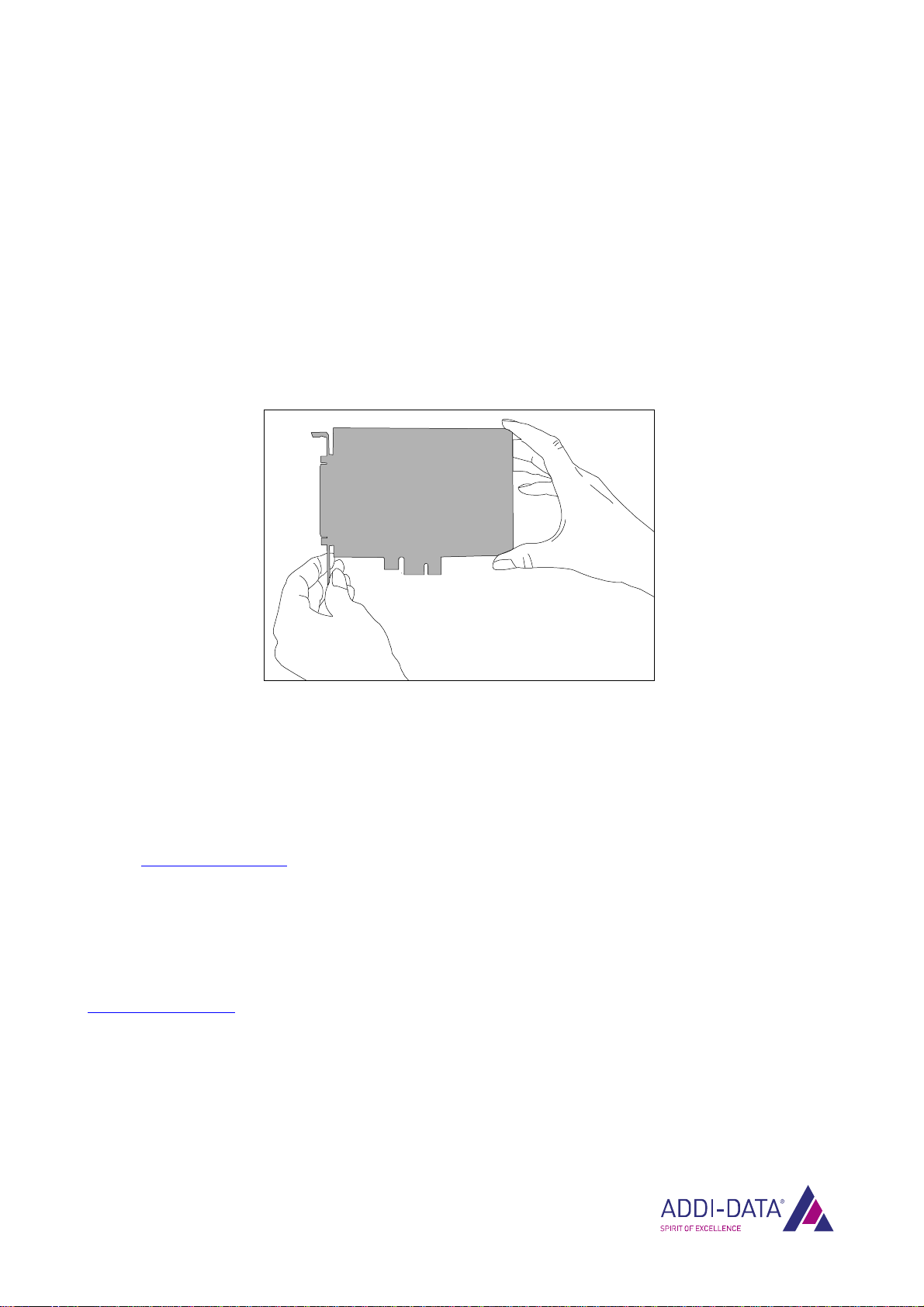
1.3 Handling of the board
Fig. 1-1: Correct handling
Hold the board cautiously at the outer end and at the slot bracket.
Do not touch the surface of the board!
1.4 Questions and updates
You can send us any questions by e-mail or call us:
E-mail: [email protected]
Phone: +49 7229 1847-0.
Manual and software download from the Internet
The latest versions of the technical manual and the standard software for the APCIe-040 board can be
downloaded for free at:
www.addi-data.com
i IMPORTANT!
Before using the board or in case of malfunction during operation,
check if there is an update available on our website (manual, drivers) or
contact us directly.
Brief description APCIe-040
2Brief description
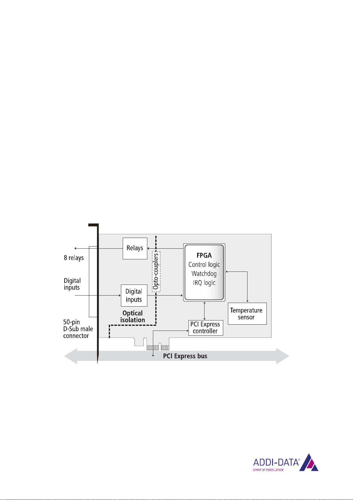
The board APCIe-040 is equipped with 7 watchdogs to monitor hardware and software
simultaneously. External devices can both be monitored (e.g. alarm system, PLC, etc.) and controlled
(e.g. modem, dialling device, etc.) with this board.
Features:
•7 watchdogs/timers
•7 digital inputs (for watchdog trigger or timer gate), 24 V, interruptible
•8 relays with change-over contacts
•2 alarm levels: Level 1 switches a warning relay and/or releases an interrupt,
Level 2 switches the reset relay (only watchdog 0 has 2 relays)
•Temperature monitoring
•Optical isolation (1000 V)
2.1 Block diagram
Fig. 2-1: APCIe-040: Block diagram
www.addi-data.com 9
Insertion and installation of the board APCIe-040
3Insertion and installation of the board
3.1 Insertion of the board
i IMPORTANT!
Please follow the safety precautions!
3.1.1 Opening the PC
Switch off the PC and all units connected to the PC.
Pull the PC mains plug from the socket.
Open the PC as described in the manual of the PC manufacturer.
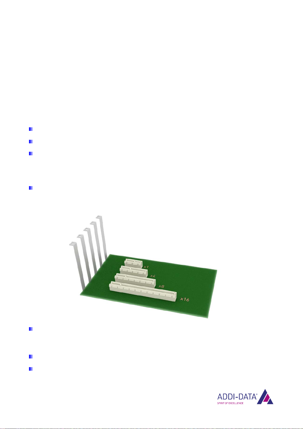
3.1.2 Selecting a slot
Select a free 1-lane (x1) or 4-lane (x4) PCI-Express slot for the board.
Fig. 3-1: PCI Express slot types
Unscrew the back cover from the selected slot.
Please follow the operating instructions provided by the PC manufacturer. Please keep the back
cover in a safe place. You will need it if you remove the board.
Please provide for a potential equalisation.
Take the board out of its protective packaging.
www.addi-data.com 10

Insertion and installation of the board APCIe-040
3.1.3 Inserting the board
Insert the board vertically from above into the selected slot.
Fig. 3-2: Slot: Insert the board
Fasten the board to the rear of the PC housing using the screw which held the back cover in place.
Fig. 3-3: PC housing: Fasten the board
Tighten all loose screws.
3.1.4 Closing the PC
Close the PC as described in the manual of the PC manufacturer.
www.addi-data.com 11
Insertion and installation of the board APCIe-040
3.2 Connecting the accessories
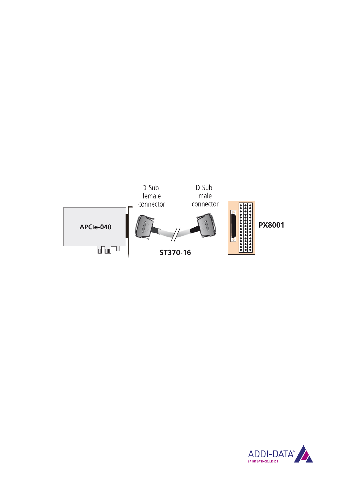
3.2.1 Cable and screw terminal panel
The relay contacts of the board APCIe-040 are connected to the peripherals via the cable ST370-16
and the screw terminal panel PX8001 (see figure below). The digital inputs are also led out over the
50-pin D-Sub male connector of the board.
In terms of electromagnetic compatibility (EMC), the cable ST370-16 has the following properties:
•Metallised connector housing
•Shielded cable
•Cable shield folded back over insulation and firmly screwed on both sides to the connector
housing.
Fig. 3-4: APCIe-040: Connection to screw terminal panel PX8001
www.addi-data.com 12

Insertion and installation of the board APCIe-040
3.2.2 Pin assignment
Fig. 3-5: APCIe-040: 50-pin D-Sub male connector
www.addi-data.com 13

Insertion and installation of the board APCIe-040
www.addi-data.com 14
3.2.3 Connection examples
1) Digital inputs (24 V)
Fig. 3-6: Connection example: Digital inputs (24 V)
2) Digital outputs (relays)
Fig. 3-7: Switching principle of the relays

Insertion and installation of the board APCIe-040
www.addi-data.com 15
3.3 Driver installation
In the document “Quick installation PC boards” (see PDF link), you can get information on the
selection of the appropriate driver and on the driver download.
The most important information on the installation of drivers of the type “ADDI-DATA Devices Driver
Multiarchitecture 32-/64-Bit for x86/AMD64” as well as on the installation of the corresponding
samples is to be found in the installation instructions (see PDF link).

Function description APCIe-040
4Function description
4.1 One or two-level alarm system
With watchdogs 1-6, a one-level alarm system can be implemented and with watchdog 0, a two-level
alarm system.
Via watchdog 0, the first alarm level can be released. This means that a warning relay is switched
(closing contact) and/or an interrupt is released after the watchdog has run down.
In the interrupt routine, a user application may analyse the reason why the watchdog has run down.
If the reason should not be found during a programmable delay, the second alarm level can be
released by switching the reset relay.
In addition, the internal computer temperature can be monitored over the onboard temperature
sensor (see Chapter 4.7).
Fig. 4-1: Operation of the one or two-level alarm system
www.addi-data.com 16

Function description APCIe-040
Fig. 4-2: Two-level alarm system: Interrupt and relay options
www.addi-data.com 17

Function description APCIe-040
Application example
In a computer system, different tasks (application programs) are monitored.
Task 1 triggers watchdog 0 (reload value = 100).
Task n
Watchdog 0
100 (Reload value)
99
….
50
100 (Reload value)
99
…
0
Trigger
Interrupt,
warning relay is
switched
Task 2Task 1
If Task 1 is blocked due to a system error, the watchdog trigger is not released and watchdog 0 runs
down. After the watchdog has run down, a yellow warning lamp is switched on via the warning relay.
In the interrupt routine, a diagnostic program is started which analyses the reason for the blocking of
Task 1.
In case the diagnostic program cannot find the reason for the problem during a programmable delay,
the reset relay is switched. This closes the hardware reset contact of the computer system and thus
restarts the computer.
4.2 Digital inputs (24 V
The board APCIe-040 has seven digital inputs over which watchdogs can be triggered or timers can be
started or stopped (see Fig. 4-1).
Table 4-1: Function range for each input
Function Meaning Options
Watchdog trigger Triggers the watchdog. Reacts to “0” and/or to “1”
(24 V) at the input.
Timer gate Starts or stops the timer. Reacts to “0” and/or to “1”
(24 V) at the input.
www.addi-data.com 18

Function description APCIe-040
The digital inputs acquire external signal statuses. The input information is loaded as a numeric value
in a memory cell of the system via the driver function. This numeric value represents the status of the
input signals.
The inputs correspond to the 24 V industry standard (IEC1131-2):
•Logic “1” corresponds to an input voltage > 19 V.
•Logic “0” corresponds to an input voltage < 14 V.
The current demand for each input is 5-8 mA at nominal voltage (see Chapter 7.4.1). The maximum
input voltage is 30 V.
i IMPORTANT!
The mains supply for the external power supply of the board must
deliver at least the power that is required for your application.
The input signals are filtered by TVS diodes, RC filters and opto-couplers. In this way, the effect of
inductive and capacitive noise is reduced.
4.3 Digital outputs (relays)
The switching principle of the relays is explained in Fig. 3-7. Each output can switch a maximum current
of 2 A.
The warning relay and the reset relay functions are software-selectable. For the digital outputs,
positive logic is used:
•Logic “1“ = Set output (connection: change-over contact with closing contact)
•Logic “0“ = Reset output (connection: change-over contact with opening contact)
4.3.1 Watchdog 0
When watchdog 0 has run down, warning relay 0 or the reset relay is switched (see Fig. 4-2). The reset
relay can be switched in two different ways:
•Mode 0: The reset relay is first reset and after 2 s set again.
•Mode 1: The reset relay is first set and after 2 s reset again.
4.3.2 Watchdogs 1-6
When watchdogs 1-6 have run down, warning relays 1-6 are switched. The latter can be reset by a
computer reset or a reinitialisation of each of watchdogs 1-6.
www.addi-data.com 19

Function description APCIe-040
www.addi-data.com 20
4.4 Watchdog
Using a software function, the 8-bit watchdog can be initialised and enabled.
The watchdog is started by the first trigger command (through software or via the digital input). This
means that the watchdog time is loaded and the watchdog starts to decrement.
In the program loop within the program to be monitored (software tasks), the trigger command has to
be called up in cyclic intervals, which prevents the watchdog time from elapsing. The watchdog time is
reloaded then and the watchdog decrements again. If the program has crashed, the trigger command
is no longer executed and the watchdog runs down. In this case, the configured alarm level is released
(see Fig. 4-1).
The watchdog statuses can be read back through software via status registers. Four units (μs, ms, s,
min) are available as time bases for the watchdog.
4.5 Timer
Independently from the PC clock, the timer provides a time base to synchronise operations, for
example. The timer is a downward counter which can release an interrupt after the programmed cycle
time has elapsed (time-out).
The seven timers of the board APCIe-040 can be programmed individually. The starting time of the
timer and the selection of the cycle time depend on the execution speed of the computer and on the
time parameters of the program to be monitored.
When the start value (reload value) of the timer is programmed, the timer is started by setting the
gate through software or via the digital input.
The current timer value and the start value (reload value) as well as status and interrupt registers can
be read back through software. Four units (μs, ms, s, min) are available as time bases for the timer.
Example
Reload value = 7
Initialisation with a rising edge
Interrupt enabled
When the timer value is “0”, the reload value “7” will be reloaded with the next valid edge and an
interrupt will be released.
Start
Clock
Timer
Underflow
Table of contents
Other Addi-Data PCI Card manuals

Addi-Data
Addi-Data APCI-2032 Parts list manual

Addi-Data
Addi-Data APCIe-1711 Parts list manual

Addi-Data
Addi-Data ADDICOM APCI-7300 Parts list manual

Addi-Data
Addi-Data ADDICOM APCI-7501 Parts list manual

Addi-Data
Addi-Data APCI-1710 User manual

Addi-Data
Addi-Data PC104-PLUS1500 Parts list manual

Addi-Data
Addi-Data APCI-3003 Parts list manual

Addi-Data
Addi-Data APCIe-1711 Parts list manual

Addi-Data
Addi-Data APCI-3701 Parts list manual


