Addi-Data APCIe-1711 Parts list manual

DIN EN ISO 9001:2008 certified Edition: 02.03-07/2016
Function Description
TTL I/O
APCIe-1711, CPCIs-1711 and APCI-1710
Multifunction counter board, optically isolated

Product information
This manual contains the technical installation and important instructions for correct commissioning
and usage, as well as production information according to the current status before printing.
The content of this manual and the technical product data may be changed without prior notice.
ADDI-DATA GmbH reserves the right to make changes to the technical data and the materials included
herein.
Warranty and liability
The user is not permitted to make changes to the product beyond the intended use, or to interfere
with the product in any other way.
ADDI-DATA shall not be liable for obvious printing and phrasing errors. In addition, ADDI DATA, if
legally permissible, shall not be liable for personal injury or damage to materials caused by improper
installation and/or commissioning of the product by the user or improper use, for example, if the
product is operated despite faulty safety and protection devices, or if notes in the operating
instructions regarding transport, storage, installation, commissioning, operation, thresholds, etc. are
not taken into consideration. Liability is further excluded if the operator changes the product or the
source code files without authorisation and/or if the operator is guilty of not monitoring the
permanent operational capability of working parts and this has led to damage.
Copyright
This manual, which is intended for the operator and its staff only, is protected by copyright.
Duplication of the information contained in the operating instructions and of any other product
information, or disclosure of this information for use by third parties, is not permitted, unless this right
has been granted by the product licence issued. Non-compliance with this could lead to civil and
criminal proceedings.
ADDI-DATA software product licence
Please read this licence carefully before using the standard software. The customer is only granted the
right to use this software if he/she agrees with the conditions of this licence.
The software must only be used to set up the ADDI-DATA products.
Reproduction of the software is forbidden (except for back-up and for exchange of faulty data
carriers). Disassembly, decompilation, decryption and reverse engineering of the software are
forbidden. This licence and the software may be transferred to a third party if this party has acquired a
product by purchase, has agreed to all the conditions in this licence contract and the original owner
does not keep any copies of the software.
Trademarks
•ADDI-DATA, APCI-1500, MSX-Box and MSX-E are registered trademarks of ADDI-DATA GmbH.
•Turbo Pascal, Delphi, Borland C, Borland C++ are registered trademarks of Borland Software
Corporation.
•Microsoft .NET, Microsoft C, Visual C++, MS-DOS, Windows XP, Windows 7, Windows 8, Windows
Server 2000, Windows Server 2003, Windows Embedded and Internet Explorer are registered
trademarks of Microsoft Corporation.
•LabVIEW, LabWindows/CVI, DASYLab, DIAdem are registered trademarks of National Instruments
Corporation.
•CompactPCI is a registered trademark of PCI Industrial Computer Manufacturers Group.
•VxWorks is a registered trademark of Wind River Systems, Inc.
•RTX is a registered trademark of IntervalZero.
www.addi-data.com 2
Warning!
The following risks result from the improper implementation of the
board and from use contrary to the regulations:
Personal injury
Damage to the board, the PC and peripherals
Pollution of the environment.
Protect yourself, others and the environment!
Read the safety precautions (yellow leaflet) carefully!
If this leaflet is not enclosed with the documentation, please contact us
and ask for it.
Observe the instructions of this manual!
Make sure that you do not forget or skip any step!
We are not liable for damages resulting from the wrong use of the board.
Pay attention to the following symbols:
NOTICE!
Designates hints and other useful information.
NOTICE!
Designates a possibly dangerous situation.
If the instructions are ignored, the board, the PC and/or
peripherals may be destroyed.
WARNING!
Designates a possibly dangerous situation.
If the instructions are ignored, the board, the PC and/or
peripherals may be destroyed and persons may be endangered.
www.addi-data.com 3

Contents TTL I/O
Contents
Warning! ...........................................................................................................................................3
Chapter overview.............................................................................................................................5
1Function description .............................................................................................................6
1.1 Board versions with “TTL I/O” function ..............................................................................................6
1.2 Block diagram .......................................................................................................................................7
1.3 Used signals ...........................................................................................................................................7
1.4 Pin assignment ......................................................................................................................................8
1.5 Connecting the accessories (cables and screw terminal panel) .......................................................11
1.6 Connection example...........................................................................................................................13
2Standard software ..............................................................................................................14
3Technical data and limit values .........................................................................................15
3.1 Digital inputs and outputs (50-pin header) ......................................................................................15
4Appendix .............................................................................................................................16
4.1 Index ....................................................................................................................................................16
5Contact and support ...........................................................................................................17
Figures
Fig. 1-1: Block diagram: “TTL I/O” function ................................................................................................7
Fig. 1-2: Pin assignment: 50-pin header and 50-pin D-Sub male connector .............................................8
Fig. 1-3: APCIe-1711: Connecting the accessories .....................................................................................11
Fig. 1-4: CPCIs-1711: Connecting the accessories ......................................................................................11
Fig. 1-5: APCI-1710: Connecting the accessories .......................................................................................12
Fig. 1-6: Connection example.....................................................................................................................13
Tables
Table 1-1: Used signals.....................................................................................................................................7
Table 1-2: Pin assignment: 50-pin D-Sub male connector and 50-pin header .............................................9
www.addi-data.com 4

Chapter overview TTL I/O
Chapter overview
In this manual, you will find the following information:
Chapter Content
1 Function description including block diagram and pin assignment
2 Standard software: Information on the API software functions
3 List of technical data and limit values
4 Appendix with index
5 Contact and support address
This document solely describes the function “TTL I/O”.
For general information on the APCIe-/CPCIs-1711 or APCI-1710, please read the respective Technical
Description of these boards (see PDF links). It contains, for example, the chapter “Inserting and
installing the board” that supports you in commissioning.
www.addi-data.com 5

Function description TTL I/O
1Function description
Via the 50-pin header, TTL signals can be connected to the board.
NOTICE!
In case other signals are connected, these have to correspond to
the TTL level to prevent the board from being damaged.
Please also note that the ports are not optically isolated and that
the board may be destroyed due to external voltage peaks!
Signals PA0 to PA7, PB0 to PB7 and PC0 to PC7 are connected in parallel to all four function modules of
the board. To avoid malfunction, the “TTL I/O” function can be loaded only in one function module.
Features:
• For each function module 3 ports (A, B, C) with 8 digital inputs/outputs each (set as inputs after the
reset)
•For each function module 1 Port (D) with 2 digital inputs/outputs (set as outputs after the reset)
1.1 Board versions with “TTL I/O” function
NOTICE!
The “TTL I/O” function can be used with every version of the
APCIe-1711, CPCIs-1711 or APCI-1710.
The I/O specifications of the different board versions are available in the Technical Description of the
APCIe-/CPCIs-1711 or APCI-/CPCI-1710 (see PDF links).
www.addi-data.com 6

Function description TTL I/O
1.2 Block diagram
Fig. 1-1: Block diagram: “TTL I/O” function
1.3 Used signals
Ports A, B and C of each function module (FM0 to FM3) each have eight inputs and outputs.
In addition, each function module has two inputs and outputs (I and J) of port D, which can only be
used for the “TTL I/O” function.
Table 1-1: Used signals
Pin name Signal type Function
PA0 to PA7 TTL Input or output (after the reset: input)
PB0 to PB7 TTL Input or output (after the reset: input)
PC0 to PC7 TTL Input or output (after the reset: input)
GND PC GND GND, not optically isolated
Kx TTL Please do not connect anything!
Ix (PD0) TTL Input or output (after the reset: output)
Jx (PD1) TTL Input or output (after the reset: output)
www.addi-data.com 7

Function description TTL I/O
Pin name Signal type Function
V. ext
PC +3.3 V
(APCIe-/CPCIs-1711)
PC +5 V
(APCI-1710)
Voltage supply
x = Number of the function module (0-3)
1.4 Pin assignment
Fig. 1-2: Pin assignment: 50-pin header and 50-pin D-Sub male connector
www.addi-data.com 8
Function description TTL I/O
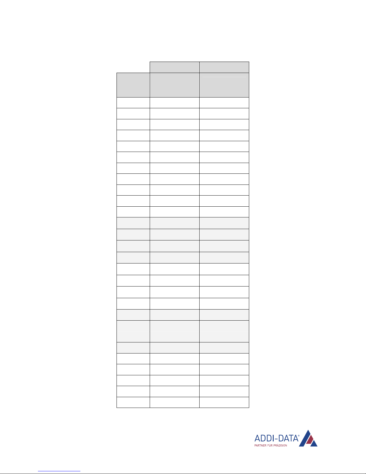
Table 1-2: Pin assignment: 50-pin D-Sub male connector and 50-pin header
FB8001 Board
Pin name
Pin No. (50-pin
D-Sub male
connector)
Pin No. (50-pin
header)
GND 34 2
GND 2 4
GND 19 6
GND 36 8
GND 4 10
GND 21 12
GND 38 14
GND 6 16
GND 24 21
GND 11 31
GND 47 41
I1217 49
I2249 47
I3248 44
I4231 42
J1250 50
J2233 48
J3232 45
J4215 43
K1 20 9
K2 37 11
K3 5 13
K4 22 15
PA0 39 17
PA1 23 18
PA2 7 19
PA3 40 20
PA4 8 22
www.addi-data.com 9
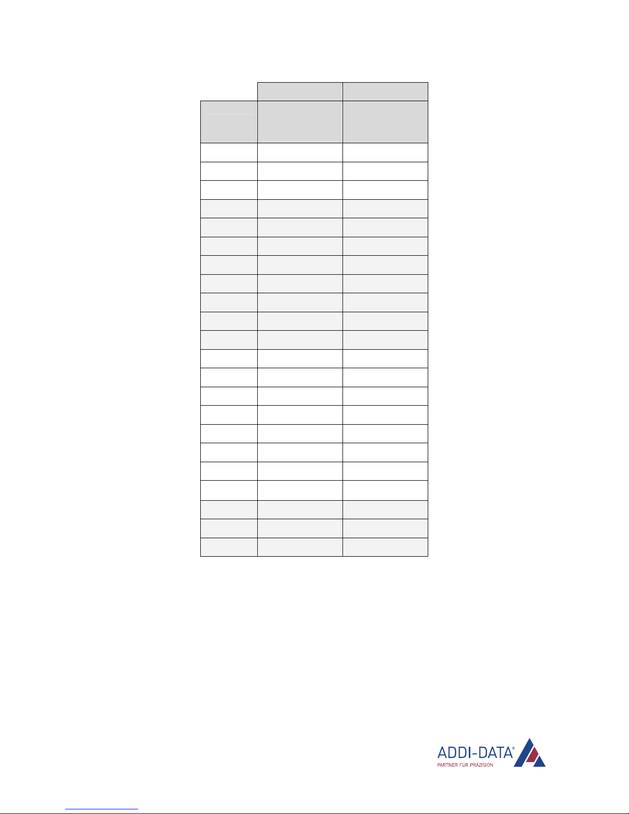
Function description TTL I/O
FB8001 Board
Pin name
Pin No. (50-pin
D-Sub male
connector)
Pin No. (50-pin
header)
PA5 41 23
PA6 25 24
PA7 9 25
PB0 26 27
PB1 10 28
PB2 43 29
PB3 27 30
PB4 44 32
PB5 28 33
PB6 12 34
PB7 45 35
PC0 13 37
PC1 46 38
PC2 30 39
PC3 14 40
PC4 3 7
PC5 35 5
PC6 18 3
PC711 1
V ext 29 36
V ext 16 46
V. ext 42 26
1: PA, PB and PC: Pull-up resistor to 3.3 V (APCIe-/CPCIs-1711) or 5 V (APCI-1710)
2: PD: Serial resistor 100 Ω
www.addi-data.com 10
Function description TTL I/O
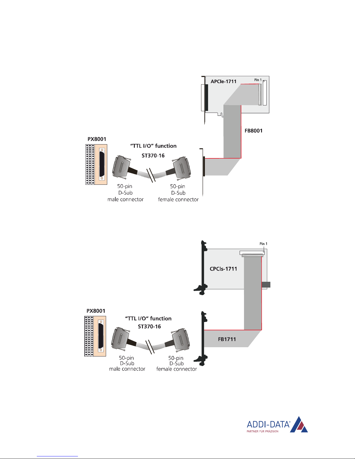
1.5 Connecting the accessories (cables and screw terminal panel)
Fig. 1-3: APCIe-1711: Connecting the accessories
Fig. 1-4: CPCIs-1711: Connecting the accessories
www.addi-data.com 11
Function description TTL I/O
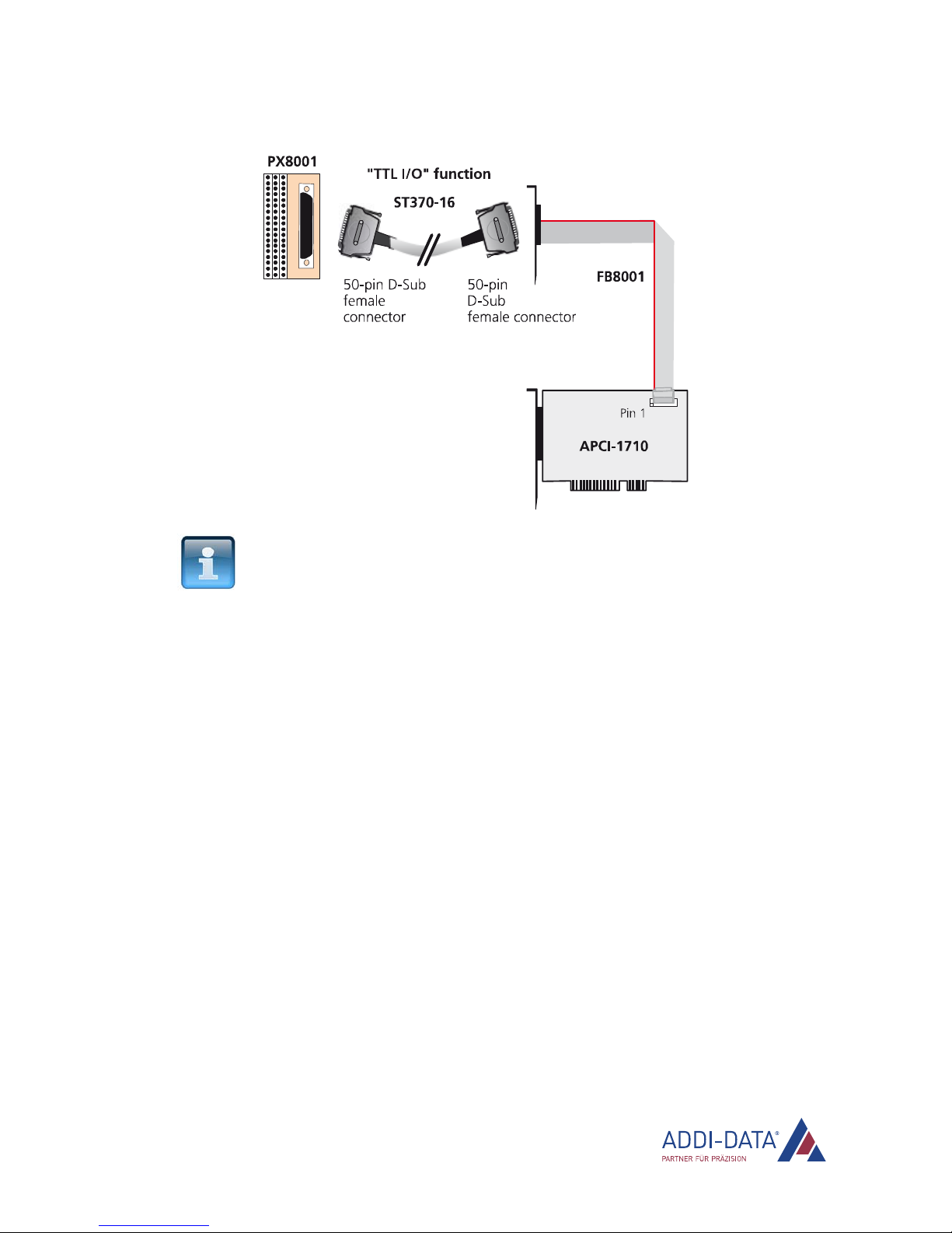
Fig. 1-5: APCI-1710: Connecting the accessories
NOTICE!
Plug the FB8001 or FB1711 cable into the connector by inserting
the red (or blue or black) cable lead into pin 1.
www.addi-data.com 12
Function description TTL I/O
www.addi-data.com 13
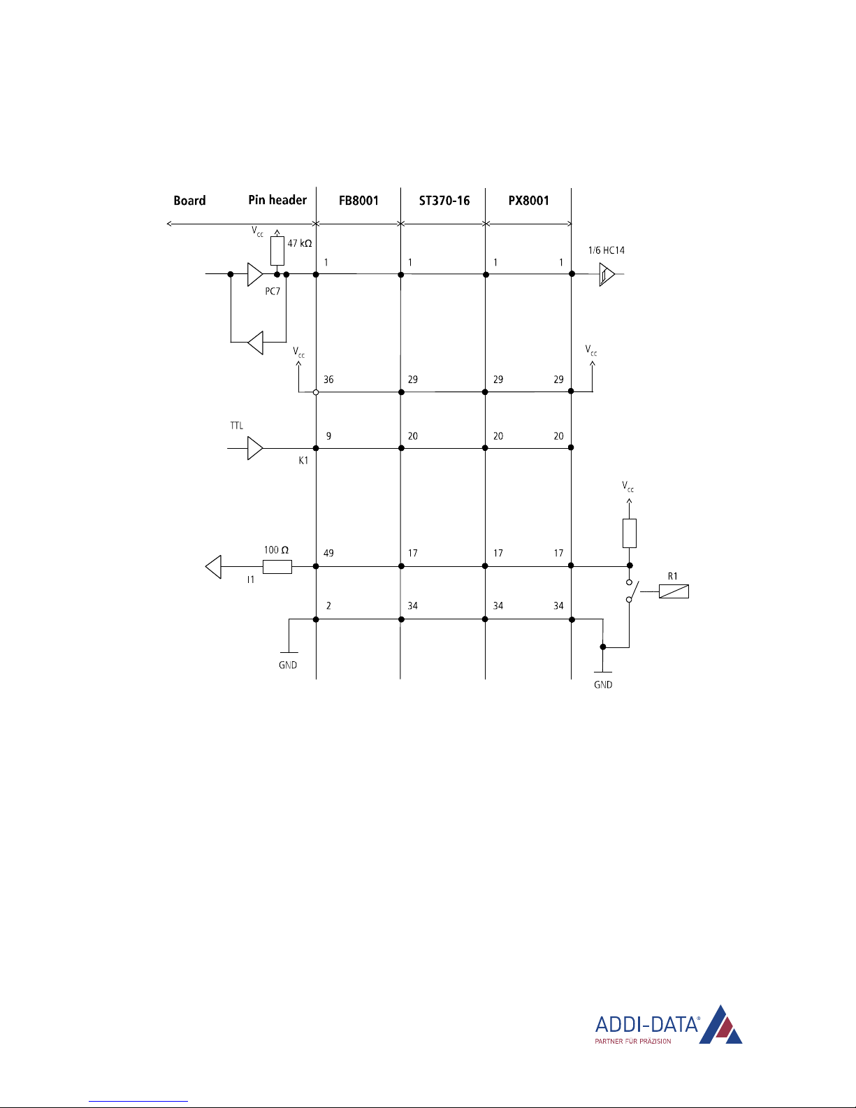
1.6 Connection example
Fig. 1-6: Connection example
Ports A, B and C are each set to VCC via a pull-up resistor (47 kΩ).

Standard software TTL I/O
2Standard software
The API software functions supported by the board are listed in an HTML document. A description on
how to access the respective file can be found in the document “Quick installation PC boards”
(see PDF link), in the chapter “Standard software”.
www.addi-data.com 14
Technical data and limit values TTL I/O
3Technical data and limit values
3.1 Digital inputs and outputs (50-pin header)
NOTICE!
The TTL inputs and outputs are not optically isolated.
Please make sure that no signal from the peripherals is connected
to the inputs and outputs when the PC system is switched off or
being booted up or shut down. This can be realised by means of a
relay or tri-state circuit between the peripherals and the TTL
inputs and outputs.
Moreover, the TTL outputs must be protected against short-circuit
through the connected signals.
APCIe-1711, CPCIs-1711
Max. input voltage: 4 V (PC supply voltage = 3.3 V ± 5%)
Max. output current: 40 mA (no short-circuit protection)
Signal thresholds:
Input logic 1: 1.7 V min.
Input logic 0: 0.8 V max.
Output logic 1: 2.4 V min. (PC supply voltage ≥3 V)
Output logic 0: 0.45 V max. (PC supply voltage ≥3 V)
APCI-1710
Max. input voltage: 4.75 V (PC supply voltage = 5 V ± 5%)
Max. output current: 25 mA (no short-circuit protection)
Signal thresholds:
Input logic 1: 2 V min.
Input logic 0: 0.8 V max.
Output logic 1: 2.4 V min. (PC supply voltage ≥4.75 V)
Output logic 0: 0.45 V max. (PC supply voltage ≥4.75 V)
www.addi-data.com 15

Appendix TTL I/O
4Appendix
4.1 Index
Accessories
Connection 11
Block diagram 7
Board versions 6
Connection example 13
Features 6
Pin assignment 8
Signals 7
Standard software 14
Technical data 15
www.addi-data.com 16

Contact and support TTL I/O
5Contact and support
Do you have any questions? Write or phone us:
Address: ADDI-DATA GmbH
Airpark Business Center
Airport Boulevard B210
77836 Rheinmünster
Germany
Phone: +49 7229 1847-0
Fax: +49 7229 1847-222
E-mail: [email protected]
Manual and software download from the Internet:
www.addi-data.com
www.addi-data.com 17
Other manuals for APCIe-1711
1
This manual suits for next models
2
Table of contents
Other Addi-Data PCI Card manuals

Addi-Data
Addi-Data APCIe-1711 Parts list manual

Addi-Data
Addi-Data PC104-PLUS1500 Parts list manual

Addi-Data
Addi-Data ADDICOM APCI-7300 Parts list manual

Addi-Data
Addi-Data APCIe-040 Parts list manual

Addi-Data
Addi-Data APCI-1710 User manual

Addi-Data
Addi-Data APCI-3003 Parts list manual

Addi-Data
Addi-Data APCI-3701 Parts list manual

Addi-Data
Addi-Data APCI-2032 Parts list manual

Addi-Data
Addi-Data ADDICOM APCI-7501 Parts list manual


