Addi-Data ADDICOM APCI-7501 Parts list manual

Technical support:
+49 (0)7223 / 9493-0
Technical description
ADDICOM APCI-7501
4-port serial interface
for the PCI bus
1
st edition 03/1999

Copyright
All rights reserved. This manual is intended for the manager and its personnel.
No part of this publication may be reproduced or transmitted by any means.
Offences can have penal consequences.
Guarantee and responsibility
Basically are effective our "general terms of delivery and payment". The manager receives
them at the latest with the invoice. Claims for guarantee and responsibility in case of injuries
and material damages are excluded, if they are due to one or some of the following causes:
- if the board has not been used for the intended purpose
- improper installation, operation and maintenance of the board
- if the board has been operated with defective safety devices or with not appropriate or
non-functioning safety equipment
- nonobservance of the instructions concerning: transport, storage, inserting the board, use,
limit values, maintenance, device drivers
- altering the board at the user's own initiative
- altering the source files at the user's own initiative
- not checking properly the parts which are subject to wear
- disasters caused by the intrusion of foreign bodies and by influence beyond the user's control.
Licence for ADDI-DATA software products
Read carefully this licence before using the software ADDIREG. The right for using this
software is given to the customer, if he/she agrees to the conditions of this licence.
- this software can only be used for configuring ADDI-DATA boards.
- copying the software is forbidden (except for archiving/ saving data and for replacing
defective data carriers)
- deassembling, decompiling, decoding and reverse engineering of the software
are forbidden.
- this licence and the software can be transferred to a third party, so far as this party
has purchased a board, declares to agree to all the clauses of this licence contract and the
preceding owner has not kept copies of the software.
Trademarks
Borland C and Turbo Pascal are registered trademarks of Borland
International, INC.
Burr-Brown is a registered trademark of Burr-Brown Corporation
Intel is a registered trademark of Intel Corporation
AT, IBM, ISA and XT are registered trademarks of International Business
Machines Corporation
Microsoft, MS-DOS, Visual Basic and Windows are registered trademarks of
Microsoft Corporation
The original version of this manual is in German. You can obtain it on request.
i
WARNING
In case of wrong uses and if the board is not used for
the purpose it is intended:
people may be the board, PC and the environment
injured peripheral may be may be
destroyed polluted
«
««
««
««
««
««
«Protect yourself, the others and the environment«
««
««
««
««
««
«
•
••
•Read absolutely the safety leaflet!
If this leaflet is not with the documentation , please contact us and ask for it.
•
••
•Observe the instructions of the manual!
Make sure that you do not forget or skip any step. We do not assume responsibility for
damages resulting from a wrong use of the board.
•
••
•Used symbols
WARNING!
It designates a possibly dangerous situation.
If the instructions are ignored the board, PC and/or peripheral
may be destroyed.
IMPORTANT!
designates hints and other useful information.
•
••
•Any question?
Our technical support is at your disposal

Table of contents APCI-7501
I
1INTENDED PURPOSE OF THE BOARD ....................................................1
1.1 Limits of use ............................................................................................ 2
2USER..................................................................................................3
2.1 Qualification ........................................................................................... 3
2.2 Personal protection................................................................................. 3
3HANDLING THE BOARD .......................................................................4
4TECHNICAL DATA................................................................................5
4.1 Electromagnetic compatibility (EMC) ..................................................... 5
4.2 Physical set-up of the board ................................................................... 5
4.3 Options ................................................................................................... 6
4.4 Limit values ............................................................................................. 6
4.5 Component scheme and block diagram .............................................. 7
5INSTALLATION.....................................................................................9
5.1 Inserting the board................................................................................ 10
5.1.1 Opening the PC.........................................................................................................10
5.1.2 Selecting a free slot ...................................................................................................10
5.1.3 Plugging the board into the slot.................................................................................11
5.1.4 Closing the PC ...........................................................................................................11
5.2 Installing the software............................................................................ 12
5.2.1 Installation under MS-DOS and Windows 3.11............................................................12
5.2.2 Installation under Windows NT / 95 .............................................................................12
5.3 Configuration of the board with ADDIREG ............................................. 12
5.3.1 Program description ..................................................................................................12
5.3.2 Registrating a new board ..........................................................................................17
5.3.3 Changing the registration of a board ........................................................................17
5.3.4 Removing the ADDIREG program ..............................................................................18
Uninstall ADDIREG...................................................................................................18
5.4 Error analysis per Internet....................................................................... 18
6CONNECTING THE PERIPHERAL .........................................................19
6.1 Connector pin assignment ................................................................... 19
6.2 Connection cables............................................................................... 20
6.3 Connection examples ......................................................................... 21
7STANDARD SOFTWARE ......................................................................22
INDEX .........................................................................................................A

Table of contents APCI-7501
III
Figures
Fig. 3-1: Wrong handling ..........................................................................................................4
Fig. 3-2: Correct handling.........................................................................................................4
Fig. 4-1: Component scheme of the APCI-7501 board ...........................................................7
Fig. 4-2: Block diagram ............................................................................................................8
Fig. 5-1: Types of slots .............................................................................................................10
Fig. 5-2: Opening the protective blister pack .........................................................................10
Fig. 5-3: Inserting the board....................................................................................................11
Fig. 5-4: Fastening the board at the back cover....................................................................11
Fig. 5-5: ADDIREG registration program ..................................................................................13
Fig. 5-6: Inserting a new board...............................................................................................14
Fig. 5-7: Communication board ............................................................................................15
Fig. 5-8: PCI boards ................................................................................................................16
Fig. 5-9: The ADDI-UNINSTALL program....................................................................................18
Fig. 6-1: 37-pin SUB-D male connector ..................................................................................19
Fig. 6-2: Connection cable ST074 (4 x 25-pin)........................................................................20
Fig. 6-3: Connection cable ST075 (4 x 9-pin)..........................................................................20
Fig. 6-4: RS 232 cabling.........................................................................................................21
Tables
Table 1-1: Intended purpose depending on the operating mode ..........................................1
Table 6-1: Assignment of the port 1........................................................................................19
Technical description Chapter 1 APCI-7501
1
1 INTENDED PURPOSE OF THE BOARD
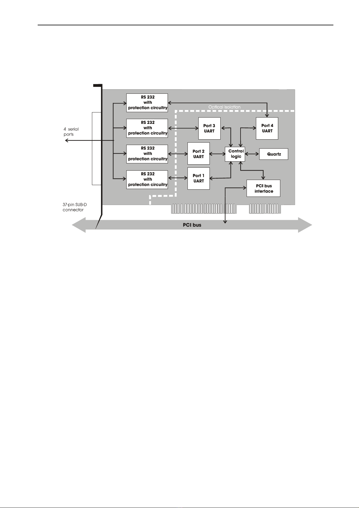
The board APCI-7501 provides the personal computer (PC) with a 4-port
asynchronous serial interface for the communication with external devices.
The board is to be used in a free PCI-5 V / 32 Bit slot. The PC is to comply with
the EU directive 89/336/EWG and the specifications for EMC protection.
Products complying with these specifications bear the normed mark.
Serial data is exchanged with external communication devices through the
37-pin SUB-D male connector of the board APCI-7501 in RS232 transmission
mode.
The board is to be connected to the peripheral through a shielded cable, which
shielding should be grounded on both ends.
The connection with our standard cable ST010 complies with the minimum
specifications as follows:
- metallized plastic hoods
- shielded cable
- cable shield folded back and firmly screwed to the connector housing.
The board supports serial communication through 4 asynchronous serial ports.
The intended purpose of the board depends on the following parameters.
Table 1-1: Intended purpose depending on the operating mode
Operating mode Distance between
transmitter and receiver Environment
APCI-7501 max. 30 m industry
APCI-7501 with option -G
(Optical isolation)
max. 30 m noisy industrial environment
The use of the board according to its intended purpose includes observing all
advises given in this manual and in the safety leaflet.
Uses beyond these specifications are not allowed. The manufacturer is not liable
for any damages which would result from the non-observance of this clause.

APCI-7501 Technical description Chapter 1
2
1.1 Limits of use
The use of the board in a PC could change the PC features regarding noise
emission and immunity. Increased noise emission or decreased noise immunity
could result in the system not being conform anymore.
Check the shielding capacity of the PC housing and cable prior to putting the
device into operation.
Make sure that the board remains in the protective blister pack until it is used.
Do not remove or alter the identification numbers of the board.
If you do, the guarantee expires.
For RS232, the signal lines are to be twisted in pairs with GND.
The housing of the peripheral connector
- is to be firmly screwed together with the shield of the cable.
- is to assure a low-resistance connection (< 100 mΩ) between the shield and
the housing of the PC.
The shield of the cable is to be earthed on both ends.

Technical description Chapter 2 APCI-7501
3
2 USER
2.1 Qualification
Only persons trained in electronics are entitled to perform the following tasks:
•installation,
•putting into operation,
•use,
•maintenance.
2.2 Personal protection
Consider the country-specific regulations about
•the prevention of accidents
•electrical and mechanical installations
•radio interference suppression.
APCI-7501 Technical description Chapter 3
4
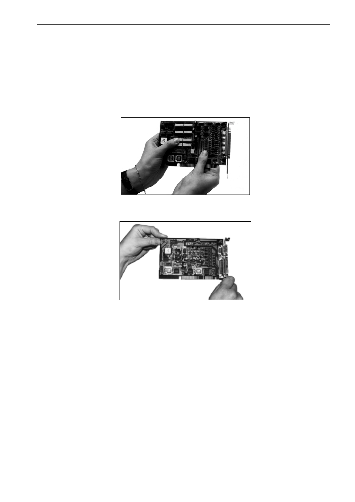
3 HANDLING THE BOARD
Fig. 3-1: Wrong handling
Fig. 3-2: Correct handling
Technical description Chapter 4 APCI-7501
5
4 TECHNICAL DATA
4.1 Electromagnetic compatibility (EMC)
The board has been subjected to EMC tests in an accredited laboratory in
accordance with the norms EN50082-2, EN55011, EN55022.
The board complies with the limit values set by the norm EN50082-2 as follows:
True value Set value
ESD .................................................................. 4 kV 4 kV
Fields ............................................................... 10 V/m 10 V/m
Burst ................................................................. 4 kV 2 kV
Conducted radio interferences ......................... 10 V 10 V
Noise emission B class
WARNING!
The EMC tests have been carried out in a specific appliance
configuration. We guarantee these limit values only in this
configuration
Consider the following aspects:
- your test program must be able to detect operation errors.
- your system must be set up so that you can find out what caused errors.
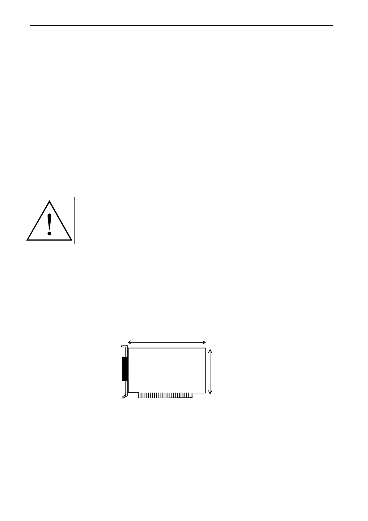
4.2 Physical set-up of the board
The board is assembled on a 4-layer printed circuit card.
131 mm
99 mm
Breadth: 19,2 mm
Weight: 156 g
Installation in: PCI 5 V / 32-bit slot
Connection to the peripheral 37-pin SUB-D male connector

APCI-7501 Technical description Chapter 4
6
4.3 Options
Option -G: 4-port serial interface with optical isolation
4.4 Limit values
Operating temperature: .................................... 0 to 60°C
Storage temperature: ........................................ -25 to 70°C
Relative humidity: ............................................ 30% to 95% non condensing
Minimum PC requirements:
- operating system: ........................................... PCI BIOS 1.0,
MS DOS 6.2 or higher
- bus speed: ...................................................... up to 33 MHz
Energy requirements:
- operating voltage of the PC: .......................... 5V ±5%
- current consumption in mA
(without load); typ: . ....................................... See table ±5%
APCI-7501 APCI-7501-G
+ 5 V from PC 315 mA
CCITT recommendation: ................................. V.24
US norm EIA: .................................................. RS 232
Max. transfer rate:
Standard: .......................................................... 112 kBd
With High-Speed Driver: ................................. up to 1 MBd1
Safety (Option -G)
Optical isolation: .............................................. 500 V
1ADDI-DATA High-Speed Driver: available for Windows NT on request.
Technical description Chapter 4 APCI-7501
7
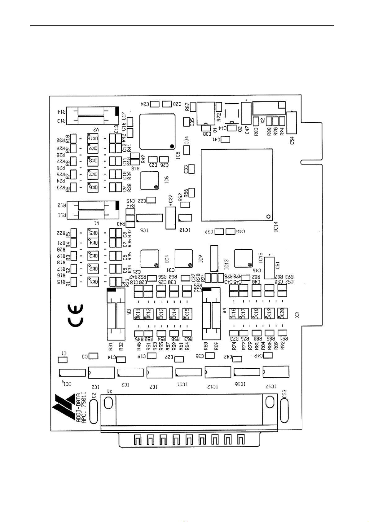
4.5 Component scheme and block diagram
Fig. 4-1: Component scheme of the APCI-7501 board
APCI-7501 Technical description Chapter 4
8
Fig. 4-2: Block diagram

Technical description Chapter 5 APCI-7501
9
5 INSTALLATION
The interrupt line and the base address of the board are set per software through
the BIOS of the PC system. Therefore, there are no settings to be made before
inserting the board.
IMPORTANT!
If you want to install simultaneously several ADDI-DATA boards,
consider the following procedure.
•Install and configure the boards one after the other.
You will thus avoid configuration errors.
1. Switch off the PC
2. Install the first board
3. Start the PC
4. Install the software (only once)
5. Configure the board
6. Switch off the PC
7. Install the second board
8. Start the PC
9. Configure the board
etc
You will find additional information to these different steps in the sections 5.1
to 5.4.
IMPORTANT!
You have installed already one or more ADDI-DATA boards in your
PC, and you wish to install an additional board?
Proceed as if you wished to install one single board.
APCI-7501 Technical description Chapter 5
10
5.1 Inserting the board
IMPORTANT!
Do observe the safety instructions.
5.1.1 Opening the PC
•Switch off your PC and all the units connected to the PC.
•Pull the PC mains plug from the socket.
•Open your PC as described in the manual of the PC manufacturer.
5.1.2 Selecting a free slot
1. Select a free PCI slot.
The following PCI slot types are available for 5V systems:
PCI-5V (32 bit) and PCI-5V (64 bit)
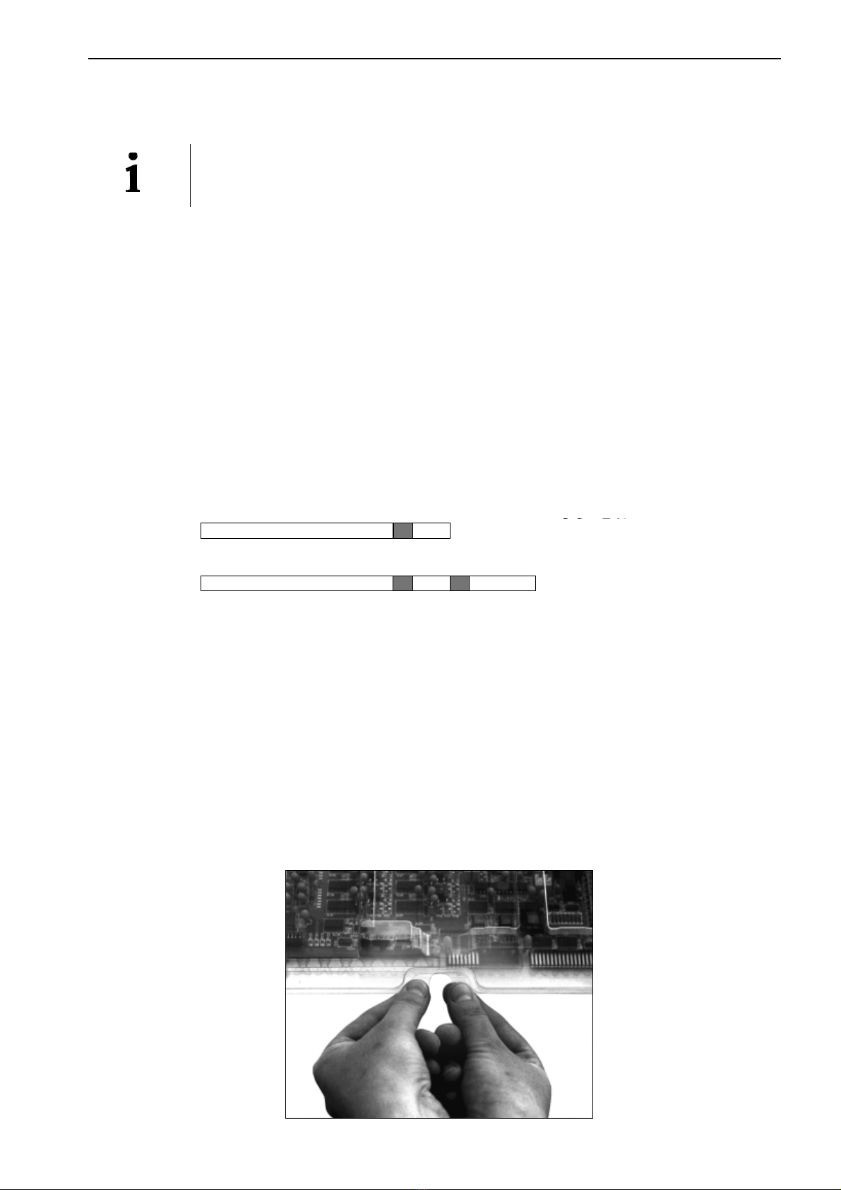
Fig. 5-1: Types of slots
32-bit
64-bit
See in the PC manual which types of slots are free.
2. Remove the back cover of the selected slot
according to the instructions of the PC manufacturer.
Keep the back cover. You will need it if you remove the board.
3. Discharge yourself from electrostatic charges.
4. Take the board out of its protective blister pack.
Fig. 5-2: Opening the protective blister pack

Technical description Chapter 5 APCI-7501
11
5.1.3 Plugging the board into the slot
•
••
•Discharge yourself from electrostatic charges.
•
••
•Insert the board vertically into the chosen slot.
Fig. 5-3: Inserting the board
•Fasten the board to the rear of the PC housing with the screw
which was fixed on the back cover.
Fig. 5-4: Fastening the board at the back cover
•
••
•Tighten all the loosen screws.
5.1.4 Closing the PC
•Close your PC as described in the manual of the PC manufacturer.

APCI-7501 Technical description Chapter 5
12
5.2 Installing the software
The CD contains:
- ADDIREG for Windows NT 4.0 and Windows 95,
- Standard software for the ADDI-DATA boards:
- 16-bit for MS-DOS and Windows 3.11
- 32-bit for Windows NT/95.
5.2.1 Installation under MS-DOS and Windows 3.11
To install the board under MS-DOS, the "ADDI-DATA software driver" is
available on request.
5.2.2 Installation under Windows NT / 95
- Select the directory PCI7501\32bit\Disk1.
- Start the set-up program "setup.exe" (double click)
- Select one of the 3 parameters
1- typical
2- compact
3- custom
Proceed as indicated on the screen and read attentively the "Software License"
and "Readme".
In "custom", you can select your operating system.
The installation program gives you further instructions.
5.3 Configuration of the board with ADDIREG
The ADDIREG registration program is a 32-bit program for Windows NT 4.0
and Windows 95.
With this program, the user can registrate all hardware information which are
necessary for the management of ADDI-DATA PC-boards.
5.3.1 Program description
IMPORTANT!
Insert first the ADDI-DATA board you want to registrate before you
start the ADDIREG program.
Once the board is installed, the registration can be tested.
By call-up of the program the following screen is displayed.

Technical description Chapter 5 APCI-7501
13
Fig. 5-5: ADDIREG registration program
Screen explanation:
Table:
The table in the middle lists the registrated boards and their respective
parameters.
Board name:
Names of the different registrated boards (e.g.: APCI-7501).
When you start the program for the first time, no board is registrated in this table.
Base address:
Selected base address of the board.
PCI slot:
Used PCI slot. If the board is no PCI board, the message "NO" is displayed.
Interrupt:
Used interrupt of the board. If the board uses no interrupt, the message "Not
available" is displayed.
DMA:
Indicates the selected DMA channel or "Not available" if the board uses no
interrupt.
More information:
Additional information like the identifier string (e.g.: PCI1500-50) or the
installed COM interfaces.
Text boxes:
Under the table you will find 6 text boxes in which you can change the
parameters of the board.
APCI-7501 Technical description Chapter 5
14
Base address name:
When the board operates with several base addresses (One for port 1, one for
port 2, etc.) you can select which base address is to be changed.
Base address:
In this box you can select the base addresses of your PC board. The free base
addresses are listed. The used base addresses do not appear in this box.
Interrupt name:
When the board must support different interrupt lines (common or single
interrupts), you can select them in this box.
Interrupt:
Selection of the interrupt number which the board is to use.
DMA name:
When the board supports 2 DMA channels, you can select which DMA channel
is to be changed.
DMA channel:
Selection of the used DMA channel.
Buttons:
Edit1:
Selection of the highlighted board with the different parameters set in the text boxes.
Click on Edit to activate the data or click twice on the selected board.
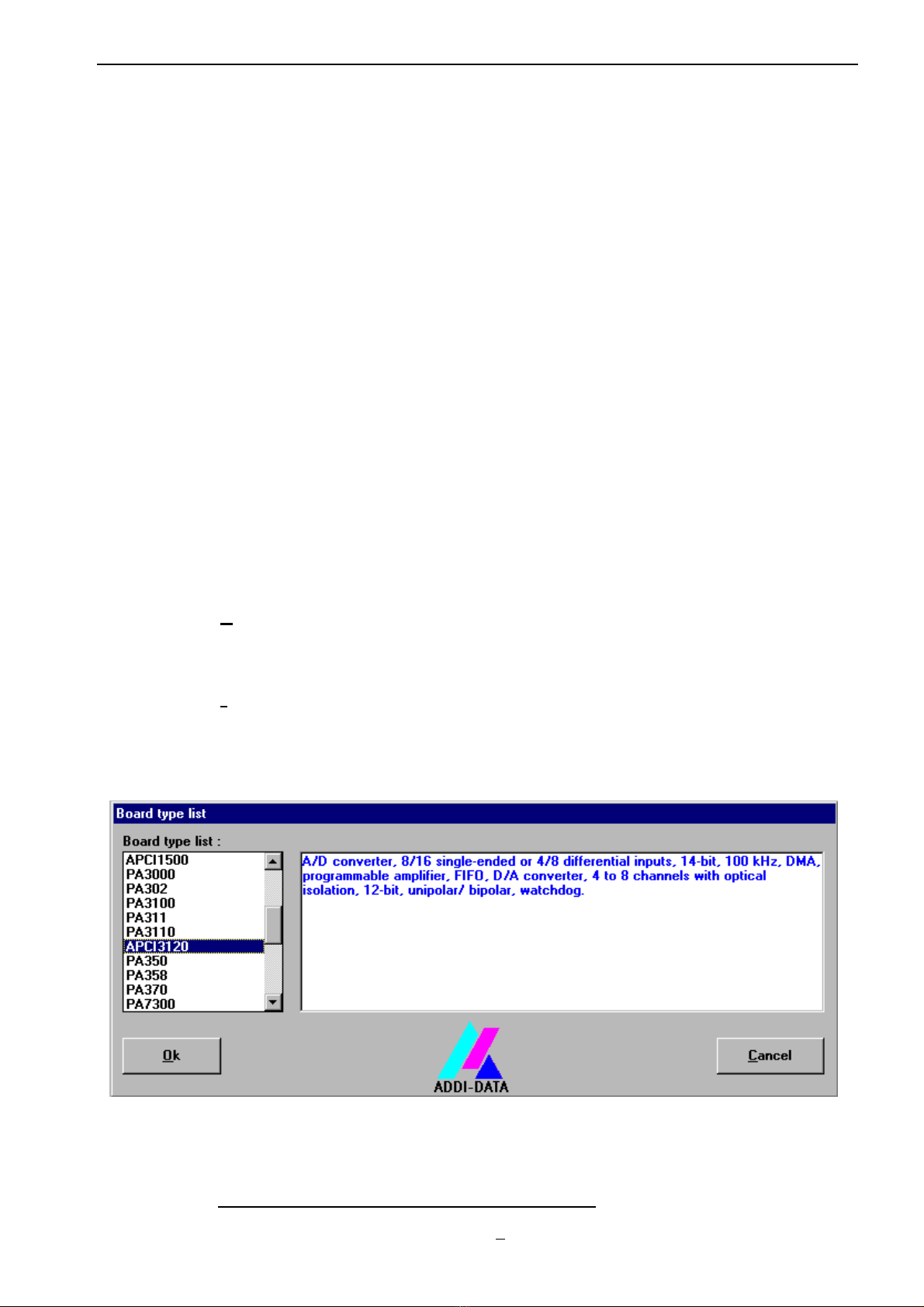
Insert:
When you want to insert a new board, click on "Insert". The following dialog
window appears:
Fig. 5-6: Inserting a new board
All boards you can registrate are listed on the left. Select the wished board. (The
corresponding line is highlighted).
On the right you can read technical information about the board(s).
Activate with "OK"; You come back to the former screen.
1"x": Keyboard shortcut. e.g.: "Alt + e" for Edit

Technical description Chapter 5 APCI-7501
15
Clear:
You can delete the registration of a board. Select the board to be deleted and
click on "Clear".
Set:
Sets the parametered board configuration. The configuration should be set
before you save it.
Cancel:
Reactivates the former parameters of the saved configuration.
Default:
Sets the standard parameters of the board.
More information:
You can change the board specific parameters like the Identifier string, the COM
number, the operating mode of a communication board, etc...
If your board does not support these information, you can not activate this button.
Notice: ADDIREG makes the difference between PCI boards and
communication boards.
Communication boards:
The following figure is the example of 4 serial interfaces.
Fig. 5-7: Communication board
If you use the standard driver for Windows, you can select the COM number.
Several options like "Module selection" and the different parameters can only be
activated if the functions are available.
This manual suits for next models
1
Table of contents
Other Addi-Data PCI Card manuals

Addi-Data
Addi-Data PC104-PLUS1500 Parts list manual

Addi-Data
Addi-Data APCIe-1711 Parts list manual

Addi-Data
Addi-Data APCI-2032 Parts list manual

Addi-Data
Addi-Data APCI-3701 Parts list manual

Addi-Data
Addi-Data APCI-1710 User manual

Addi-Data
Addi-Data APCIe-1711 Parts list manual

Addi-Data
Addi-Data APCIe-040 Parts list manual

Addi-Data
Addi-Data ADDICOM APCI-7300 Parts list manual

Addi-Data
Addi-Data APCI-3003 Parts list manual


