Adec 500 User manual
-DEC
500"
Owner's
Guide
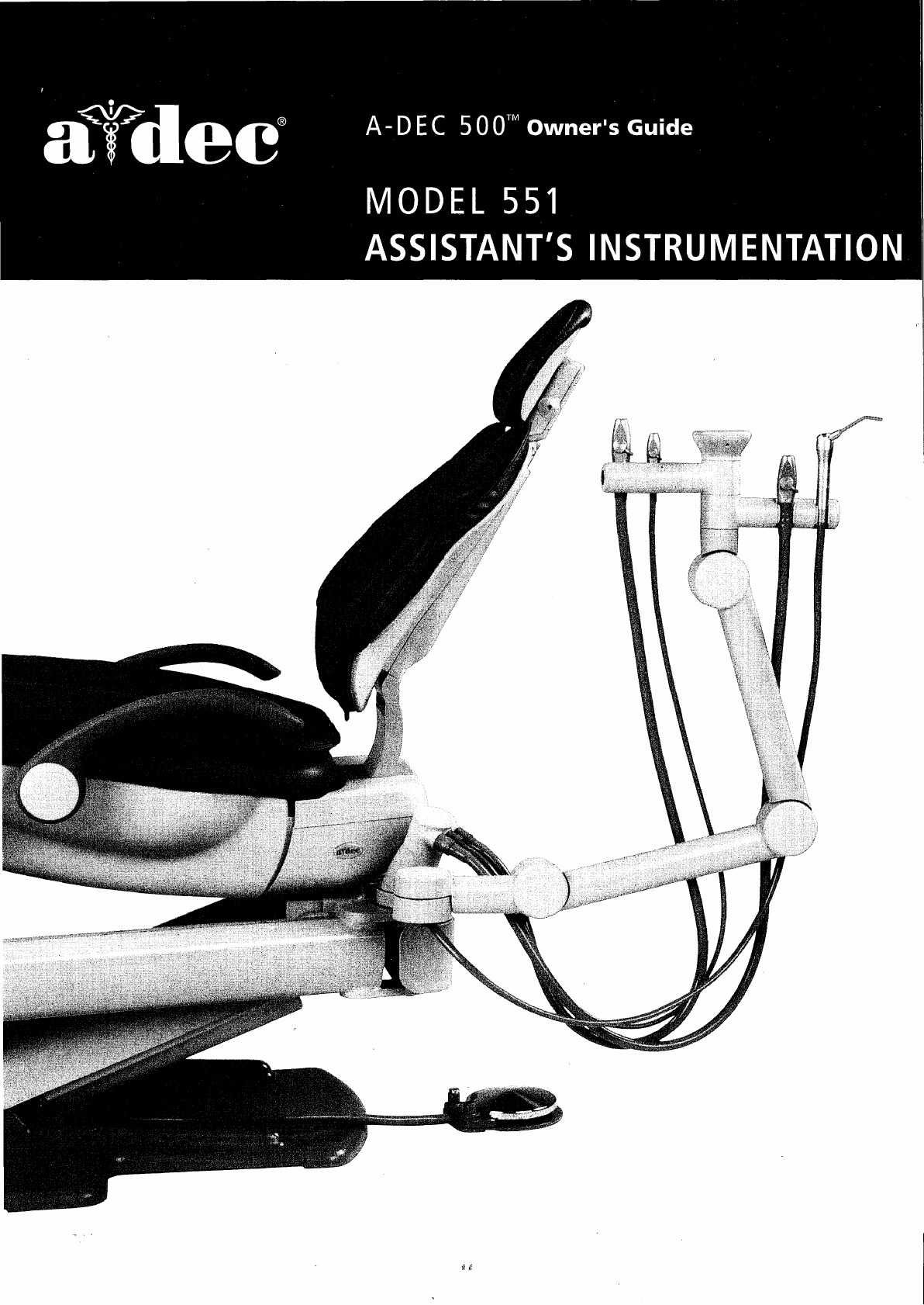
MODEL
551
ASSISTANT
S
INSTRUMENTATION
A
A
aídec
A-dec
500
Assistant's
Instrumentation
Quick
Start
Guide
A-dec's
standard
assistant's
package
includes
syringe,
HVE,
and
saliva
and
Saliva
Ejector
About
the
ejector.
Optional
instruments
may
include
an
additional
HVE.
The
Assistant's
assistant's
vacuum
instruments
are
fully
autoclavable
and
have
quick
Instrumentation
disconnect
attachments
that
remove
easily
for
cleaning.
_
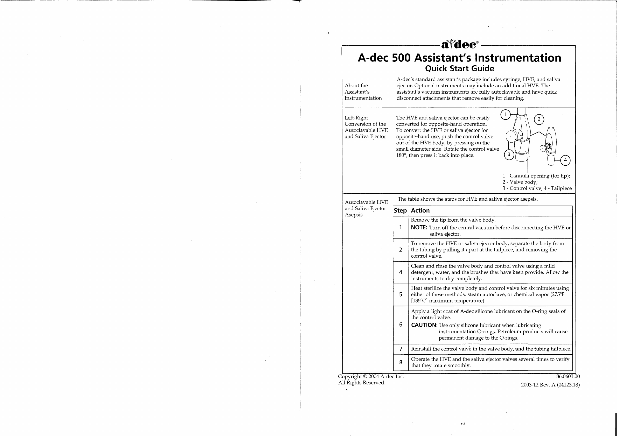
Left-Right
The
HVE
and
saliva
ejector
can
be
easily
Conversion
of
the
converted
for
opposite-hand
operation.
Autoclavable
HVE
To
convert
the
HVE
or
saliva
ejector
for
opposite-hand
use,
push
the
control
valve
out
of
the
HVE
body,
by
pressing
on
the
small
diameter
side.
Rotate
the
control
valve
180°,
then
press
it
back
into
place.
1
-
Cannula
opening
(for
tip);
2
-
Valve
body;
3
-
Control
valve;
4
-
Tailpiece
Autoclavable
HVE
and
Saliva
Ejector
Asepsis
The
table
shows
the
steps
for
HVE
and
saliva
ejector
asepsis.
Step|
Action
Remove
the
tip
from
the
valve
body.
T
|
NOTE:
Turn
off
the
central
vacuum
before
disconnecting
the
HVE
or
saliva
ejector.
To
remove
the
HVE
or
saliva ejector
body,
separate
the
body
from
2
|
the
tubing
by
pullingit
apart
at
the
tailpiece,
and
removing
the
control
valve.
Clean
and
rinse
the
valve
body
and
control
valve
using
a
mild
4
|
detergent,
water,
and
the
brushes
that
have
been
provide.
Allow
the
instrumenis
to
dry
completely.
Heat
sterilize
the
valve
body
and
control
valve
for
six
minutes
using
5
either
of
these
methods:
steam
autoclave,
or
chemical
vapor
(275°F
[135°C]
maximum
temperature).
Apply
a
light
coat
of
A-dec
silicone
lubricant
on
the
O-ring
seals
of
the
control
valve.
©
6
|
CAUTION:
Use
only
silicone
lubricant
when
lubricating
instrumentation
O-rings.
Petroleum
products
will
cause
permanent
damage
to
the
O-rings.
7
|
Reinstall
.the
control
valve
in
the
valve
body,
and
the
tubing
tailpiece.
8
Operate
the
HVE
and
the
saliva
ejector
valves
several
times
to
verify
that
they
rotate
smoothly.
Copyright
©
2004
A-dec
Inc.
All
Rights
Reserved.
À.
sê
86.0603.00
2003-12
Rev.
A
(04123.13)

Sterilizing
the
HVE
Tip
adec’
It
is
recommended
that
the
stainless
steel
tips
used
on
the
HVE
be
heat
sterilized
between
patients
using
either
of
the
following
methods:
steam
autoclave,
or
chemical
vapor
(275°F
[135°C]
maximum
temperature;
four
minutes
at
temperature).
If
you
are
using
disposable
HVE
tips,
be
sure
to
replace
them
with
new
tips
between
patients.
The
table
shows
the
steps
for
sterilizing
the
HVE
tip.
Step
|
Action
1
|
Remove
the
HVE
tip
from
the
HVE
valve
body.
>
Clean
and
rinse
the
HVE
tip
using
a
mild
detergent
and
water,
then
allow
the
tip
to
completely
dry.
3
|
Sterilize
the
HVE
tip
using
one
of
the
recommended
methods.
NOTE:
A-dec
HVE
Cannula
Opening:
Standard
A-dec
HVE
—
0.435"
+
0.006"
(11.05
+
0.15
mm).
A-dec
15
mm
HVE
-
.592"
(14.8
mm).
If
not
using
A-dec
HVE
tips,
select
a
tip
that
is
compatible
with
your
HVE
cannula
opening.
A-dec
Saliva
Ejector
Cannula
Opening:
A-dec
Saliva
Ejector
—
0.265
+
0.006"
(6.73
+
0.15
mm)
Select
a
tip
that
is
compatible
with
your
saliva
ejector
cannula
opening.
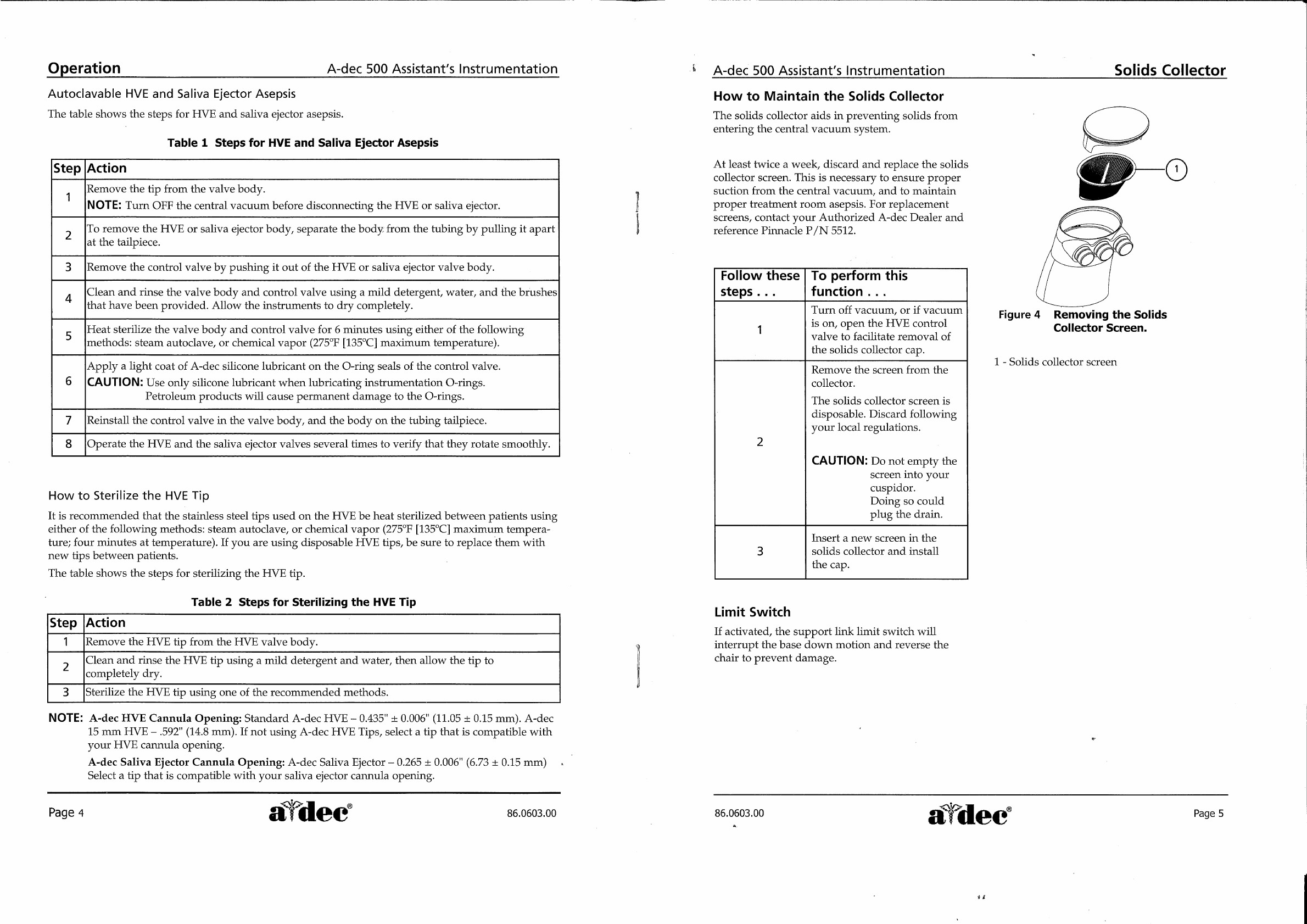
Solids
Collector
The
solids
collector
aids
in
preventing
solids
from
entering
the
central
vacuum
system.
At
least
twice
a
week,
discard
and
replace
the
solids
collector
screen.
This
is
necessary
to
ensure
proper
suction
from
the
central
vacuum,
and
to
maintain
proper
treatment
room
asepsis.
The
table
shows
the
steps
for
sterilizing
the
HVE
tip.
Step
|
Action
Turn
off
vacuum,
if
vacuum
is
on,
open
the
HVE
control
valve
to
1
,
,
facilitate
removal
of
the
solids
collector
cap.
Remove
the
screen
from
the
collector.
The
solids
collector
screen
is
disposable.
Discard
following
your
local
regulations.
CAUTION:
Do
not
empty
the
screen
into
your
cuspidor.
Doing
so
could
plug
the
drain.
3
|
Insert
a
new
screen
in
the
solids
collector
and
install the
cap.
Limit
Switch
If
activated,
the
support
link
limit
switch
will
interrupt
the
base
down
motion
and
reverse
the
chair
to
prevent
damage.
Copyright
©
2004
A-dec
Inc.
All
Rights
Reserved.
86.0603.00
2003-12
Rev.
A
(04123.13)
A-dec
500
Assistant’s
Instrumentation
Owner’s
Guide
Я
Copyright
Copyright
©
2004
A-dec
Inc.
All
Rights
Reserved.
2601
Crestview
Drive,
Newberg,
OR
97132
USA
Printed
in
USA.
A-dec
Inc.
makes
no
warranty
of
any
kind
with
regard
to
the
content
of
this
document,
including
but
not
limited
to,
the
implied
warranties
of
merchantability
and
fitness
for
a
particular
purpose.
A-dec
Inc.
shall
not
be
held
liable
for
any
errors
contained
herein
or
any
consequential
or
other
damages
concerning
the
furnishing,
performance,
or
use
of
this
material.
The
information
in
this
document
is
subject
to
change
without
notice.
If
you
find
any
problems
with
this
document,
please
report
them
to
us
in
writing.
A-dec
Inc.
does
not
warrant
that
this
document
is
error-free.
All
other
non
A-dec
products
or
services
mentioned
in
this
document
are
covered
by
the
trademarks,
service
marks,
or
product
names
designated
by
the
companies
marketing
those
products.
Trademarks
A-dec
500,
A-dec
logo,
Cascade,
Cascade
Master
Series,
Century
Plus,
Continental,
Decade,
Performer,
Preference,
Preference
Collection,
and
Radius
are
A-dec
trademarks
registered
in
the
U.S.
Patent
and
Trademark
office.
A-dec,
A-dec
500
and
ICX
are
also
trademarks
of
A-dec
Inc.
www.a-dec.com
a
=.
A-dec
500
Assistant's
Instrumentation
Warranty
Use
this
box
to
log
your
equipment
information.
Warranty
Information
Serial
number
Model
number
Date
purchased
A-dec”
warrants
all
products
against
defects
in
material
or
workmanship
for
one
year
from
time
of
delivery.
A-dec's
sole
obligation
under
the
warranty
is
to
provide
parts
for
the
repair,
or
at
its
option,
to
provide
the
replacement
product
(exclud-
ing labor).
The
buyer
shall
have
no
other
remedy.
(All
special,
incidental,
and
coincidental
damages
are
excluded.)
Written
notice
of
breach
of
warranty
must
be
given
to
A-dec
within
the
warranty
period.
The
warranty
does
not
cover
damage
resulting
from
improper
installation
or
maintenance,
accident
or
misuse.
The
warranty
does
not
cover
damage
resulting
from
the
use
of
cleaning,
disinfecting
or
sterilization
chemicals
and
processes.
The
warranty
also
does
not
cover
light
bulbs.
Failure
to
follow
instructions
provided
in
A-dec's
Owner's
Guide
(operation
and
maintenance
instructions)
may
void
the
warranty.
A-dec
warrants
A-dec
dental
chair
cylinders,
both
lift
and
tilt,
for
ten
years
from
the
date
of
purchase
of
the
chair
or
the
cylinder.
This
warranty
is
retroactive
to
A-dec
chair
cylinders
already
in
the
field.
The
warranty
covers
chair
cylinders
A-dec
finds
to
have
manufacturing
related
irregularities.
Stool
cylinders
are
covered
under
A-dec's
one-year
warranty.
No
other
warranties
as
to
merchantability
or
otherwise
are
made.
atde
oa
REF:
GIP
©
S
/
N:<B42828
§
2601
CRESTVIEW
DRIVE
|
NEWBERG,
OREGON
97132
USA
>
MADE
IN
AT
USA
PATS.
100V~
10
AMPS
MAX
PENDING
12CJ
©
C €
J
c
US
0086
UL2601-1
C22.2
NO.
601.1
し
LABEL
P/N:
051.709.00
REV
2
)
SSIE,
DENTAL
CHAIR
OX
^
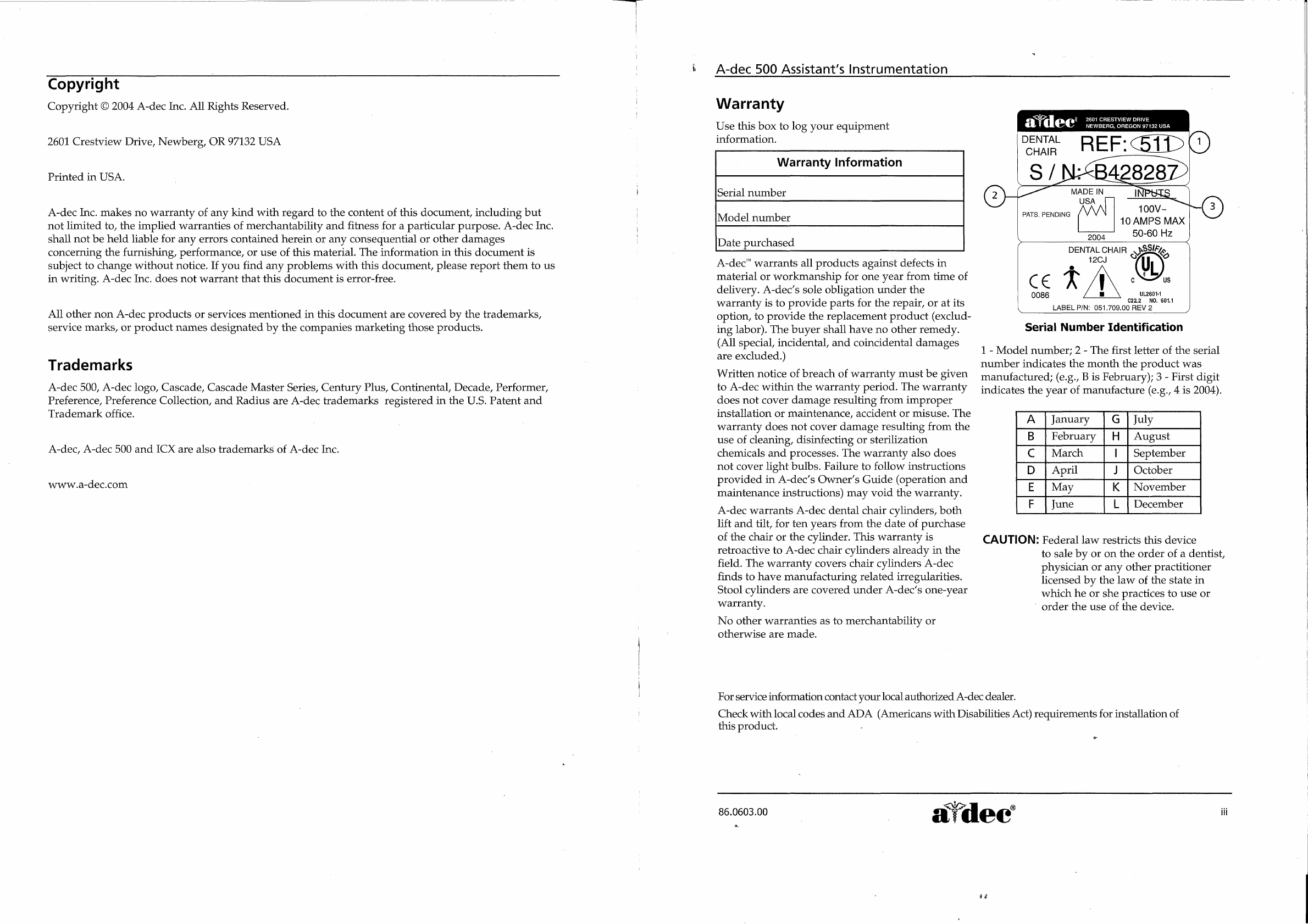
Serial
Number
Identification
1
-
Model
number;
2
-
The
first
letter
of
the
serial
number
indicates
the
month
the
product
was
manufactured;
(e.g.,
B
is
February);
3
-
First
digit
‘ov
ο
indicates
the
year
of
manufacture
(e.g.,
4
is
2004).
A
|
January
G
|
July
B
|
February
|
H
|
August
C
|
March
|
|
September
D
|
April
J
|
October
E
|
May
K
|
November
F
|
June
L
|
December
CAUTION:
Federal
law
restricts
this
device
to
sale
by
or
on
the
order
of
a
dentist,
physician
or
any
other
practitioner
licensed
by
the
law
of
the
state
in
which
he
or
she
practices
to
use
or
‘
order
the
use
of
the
device.
For service
information
contact
your
local
authorized
A-dec
dealer.
Check
with
local
codes
and
ADA
(Americans
with
Disabilities
Act)
requirements
for
installation
of
this
product.
tor
A
86.0603.00
。
|
al
dec
я.
e
A-dec
500
Assistant’s
Instrumentation
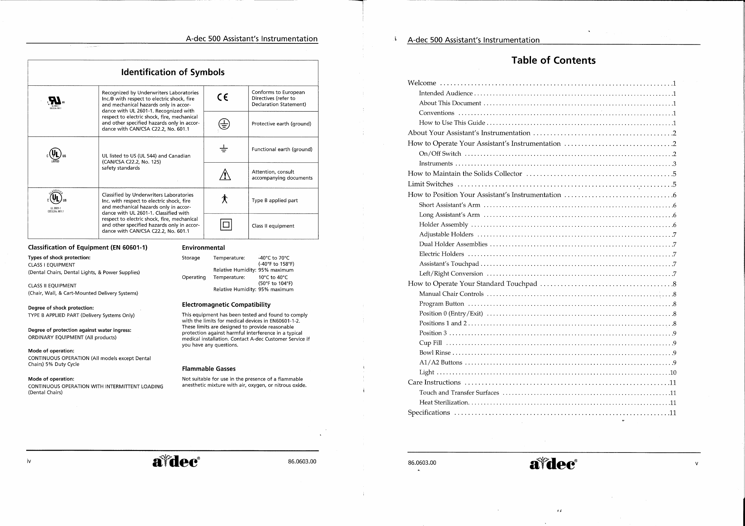
Identification
of
Symbols
Recognized
by
Underwriters
Laboratories
Conforms
to
European
Inc.®
with respect
to
electric
shock,
fire
С
€
Directives
(refer
to
~
개
and
mechanical
hazards
only
in
accor-
Declaration
Statement)
“ee
dance
with
UL
2601-1.
Recognized
with
respect
to
electric
shock,
fire,
mechanical
and
other
specified
hazards
only
in
accor-
©
Protective
earth
(ground)
dance
with
CAN/CSA
C22.2,
No.
601.1
o
=
Functional
earth
(ground)
c
US
UL
listed
to
US
(UL
544)
and
Canadian
LISTED
(CAN/CSA
C22.2,
No.
125)
safety
standards
.
A
Attention,
consult
|
accompanying
documents
SRE
:
(UL)
Classified
by
Underwriters
Laboratories
e
|
KOL)
us
Inc.
with
respect
to
electric
shock,
fire
x
Type
B
applied
part
UL
2601-1
and
mechanical
hazards
only
in
accor-
-
6011
dance
with
UL
2601-1.
Classified
with
respect
to
electric
shock,
fire,
mechanical
and
other
specified
hazards
only
in
accor-
Г]
Class
II
equipment
dance
with
CAN/CSA
C22.2,
No.
601.1
Classification
of
Eguipment
(EN
60601-1)
Types
of
shock
protection:
CLASS
|
EQUIPMENT
(Dental
Chairs,
Dental
Lights,
&
Power
Supplies)
CLASS
IT
EQUIPMENT
(Chair,
Wall,
&
Cart-Mounted
Delivery
Systems)
Degree
of
shock
protection:
TYPE
B
APPLIED
PART
(Delivery
Systems
Only)
Degree
of
protection
against
water
ingress:
ORDINARY
EQUIPMENT
(All
products)
Mode
of
operation:
CONTINUOUS
OPERATION
(All
models
except
Dental
Chairs)
5%
Duty
Cycle
Mode
of
operation:
CONTINUOUS
OPERATION
WITH
INTERMITTENT
LOADING
(Dental
Chairs)
Environmental
-40°C
to
70°C
(-40°F
to
158°F)
Relative
Humidity:
95%
maximum
Operating
Temperature:
10°C
to
40°C
(50°F
to
104°F)
Relative
Humidity:
95%
maximum
Storage
Temperature:
Electromagnetic
Compatibility
This
equipment
has
been
tested
and
found
to
comply
with
the
limits
for
medical
devices
in
EN60601-1-2.
These
limits
are
designed
to
provide
reasonable
protection
against
harmful
interference
in
a
typical
medical
installation.
Contact A-dec
Customer
Service
if
you
have
any
questions.
Flammable
Gasses
Not
suitable
for
use
in
the
presence
of
a
flammable
anesthetic
mixture
with
air,
oxygen,
or
nitrous
oxide.
NE
®
dec
86.0603.00
A-dec
500
Assistant's
Instrumentation
Table
of
Contents
Welcome
eee
eee
due
eee
eue
1
Intended
Audience
eee
eee
eee.
1
About
TIhis
Document
..
e
erra
a
1
Conventions
........................................,.....
aaa
1
How
to
Use
This
Guide
ân
1
About
Your
Assistant's
Instrumentation
.........................................
2
How
to
Operate
Your
Assistant's
Instrumentation
................................
2
On/OffSwithh
......................
ea
2
Instruments
eee
ων
3
How
to
Maintain
the
Sohiids
Collector
eee
ee
een
eee
5
LimitSwitches
.......................
ea
ーーー
κ
κ
ων
5
How
to
Position
Your
Assistant's
Instrumentation
................................
6
Short
Assistant's
Arm
.....................
K
νο
ον
6
Long
Assistant's
Arm
................
ce
cette
tent
e
ees
6
HolderAssembiy
..............................
еее
нии
иначе
еек
6
AdjustableHolderss
...................................
an
7
Оиа!
Но4ег
АззетЬПез
........
неа
н
요
ㅇ
요
요
이
ㅇ
교
요
ㅇ
교
ㅇ
교
요요
요요
교
요 요
요요
이
요
요
요 이
이 이
이 이
이 이 이
7
ElectricHolders
..........................
ερ
ρω
εν
ον
νοκ
ρω
εννοω
ε
ερ
ον
νε
νε ρε
ο
νο
ων
7
Assistant's
Touchpad
.
7
ГеН/
Е1эТЕ
Сопуег10п
.......
иен
ини
eee
renerne
7
How
to
Operate
Your
Standard
Touchpad
................................,......
8
ManualChairControls
..................................
.....8
Program
Button
.......................
R
rrenee
8
Position
O
(Entry
/Exit)
...................
ea
8
Positionsland2...............................
eee
„8
Position
3
K
нанени
9
Cup
Fill
esse
died
eee
9
Bowl
Rinse
idée
eee
ο
ρε
εν
ον
9
AT/A2
Buttons
.......
υἷυἶἷ
e
9
Light
K
K
reen
rere
10
Care
_InmnstrucHong
,,
erere
11
Touch
and
Transfer
Surfaces
..
нение
ине
nenee
11
Heat
Sterilization.
,
eee
rnvsree
11
Specificatlons
.................
eee
11
86.0603.00
i'dec
する

A-dec
500
Assistant's
Instrumentation
Tables
Table
1
—
Steps
for
HVE
and
Saliva
Ejector
Asepsis
....................,..................
4
Tabple2-
9teps
for
Sterilizing
theHVETIip
rr
4
Illustrations
Figure
1
—
Parts
of
the
Assistant’s
Instrumentation
.....................,..................
2
Figure2-
Solids
Collector
ее
нина
нии
ини
е
нии
тененни
я
2
Figure
3
—
Left/Right-Hand
Conversion
of
the
Autoclavable
HVE
and
Saliva
Ejector
.........
3
Figure
4
—
Removing
the
Solids
Collector
Screen
cence
tenes
6
Figure
5
—
Rotation
of
the
Holder
Assembly
............................................
6
Figure
6
—
Positioning
Individual
Holders
....................................,.........
7
Figure
7ーFHunctions
ot
Standard
Touchpad
ων
8
vi
adec
86.0603.00
A-dec
500
Assistant’s
Instrumentation
About
This
Document
About
this
Document
Welcome
Welcome
to
the
A-dec
500
Assistant’s
Instrumentation
Owner's
Guide.
This
guide
provides
an
easy
to
use
source
of
technical
information
for
servicing
and
maintaining
your
assistant’s
instrumentation.
Intended
Audience
This
guide
is
intended
for
doctors
and
dental
staff
to
use
when
operating
and
maintaining
A-dec
500
assistant’s
instrumentation.
About
this
Document
This
document
contains
*
instructions
on
left/right
conversion
of
a
HVE
and
saliva
ejector
*
maintenance
procedures
for
the
solid
collector
.
detail
on
the
functions
of
the
touchpad,
and
.
product
specifications.
Conventions
A
number
of
items
and
instructions
appear
throughout
this
document.
The
formatting
conventions
are
designed
to
make
it
quick
and
easy
to
find
and
understand
information.
e
References
to
sections,
or
reference
documentation
appear
in
italic
type,
e.g.,
How
to
Operate
the
Delivery
System.
e
Important
supplemental
information
about
the
covered
topic
appears
as
a
note,
e.g.,
NOTE:
The
foot
control
also
has....
¢
Bubble
numbers,
callouts,
and
tables
identify
key
components
in
an
illustration.
How
to
Use
this
Guide
This
guide
provides
detailed
descriptions
and
operation
instructions
for
the
use
of
the
A-dec
500
assistant’s
instrumentation.
Before
using
the
assistant’s
instrumentation,
review
this
document
to
get
a
feel
for
the
capabilities
of
the
assistant’s
instrumentation
and
its
to
operation.
Make
note
of
all
cautions
and.
warnings.
86.0603.00
ο
σα
Page
1
$e

Operation
A-dec
500
Assistant's
Instrumentation
About
Your
Assistant’s
Instrumentation
A-dec’s
standard
assistant’s
instrumentation.
package
includes
autoclavable
syringe,
HVE,
and
saliva
ejector.
Optional
instruments
may
include
an
additional
HVE.
The
solids
collector
is
also
a
part
of
the
assistant’s
instrumentation,
located
at
the
end
of
the
assistant’s
instrumentation
arm.
The
assistant’s
vacuum
instruments
are
fully
autoclavable
and
have
quick
disconnect
attachments
that
are
easily
removed
for
cleaning.
How
to
Operate
Your
Assistant’s
Instrumentation
On/Off
Switch
There
are
two
power
source
locations
for
the
assistant's
instrumentation,
the
Power
On/Off
button
on
the
chair
and
the
delivery
system
master
On/Off
toggle.
Figure
1
Parts
of
the
Assistant's
Instrumentation.
Power
On/Off
Button
The
Power
On/Off
button
is
located
on
the
base
of
the
chair.
This
function
allows
you
to
engage
power
or
disengage
power
to
the
entire
system
at
the
touch
of
a
button.
When
the
button
is
pressed
in,
the
system
has
power.
When
the
button
is
out,
the
system
has
no
power.
Figure
2.
Solids
Collector.
Delivery
System
Master
On/Off
Toggle
The
master
On/Off
toggle,
located
on
the
right
1
-
Autoclavable
HVE;
2
-
Autoclavable
syringe;
side
of
the
control
head,
controls
the
utilities
for
the
>"
Autoclavable
saliva
ejector;
4
-
Holder
assembly;
delivery
system
as
well
as
other
modules
mounted
5
-
Touchpad;
6
-
Solids
collector
to
the
chair.
CAUTION:
For
prolonged
life
of
your
equipment,
turn
power
OFF
when
not
in
use.
86.0603.00
Page
2
_
dec
A-dec
500
Assistant's
Instrumentation
Instruments
Autoclavable
Syringe
For
information
on
the
operation,
care,
and
maintenance
of
A-dec's
autoclavable
syringe,
refer
to
your
Autoclavable
Syringe
Owner's
Guide
(P/N
85.0680.00).
Autoclavable
HVE
and
Saliva
Ejector
The
autoclavable
HVE
and
saliva
ejector
are
equipped
with
a
quick
disconnect
to
remove
the
valve
body
from
the
tubing
for
cleaning
and
autoclaving.
Left/Right-Hand
Conversion
of
the
Autoclavable
HVE
and
Saliva
Ejector
the
Autoclavable
HVE
and
The
HVE
and
saliva
ejector
can
be
easily
converted
Saliva
Ejector
for
operation
from
either
side
of
the
chair.
1
-
Cannula
opening
(for
tip);
2
-Valve
body;
To
convert
the
HVE
or
saliva
ejector
to
one
side
or
3
-
Control
valve;
4
-
Tailpiece
the
other,
push
the
control
valve
out
of
the
HVE
body,
by
pressing
on
the
small
diameter
side.
Rotate
the
control
valve
180°,
then
push
it
back
into
place.
Figure
3
Left/Right-Hand
Conversion
of
Operation
|
|
86.0603.00
a
dec
À.
Page
3
Operation
A-dec
500
Assistant's
Instrumentation
Autoclavable
HVE
and
Saliva
Ejector
Asepsis
The
table
shows
the
steps
for
HVE
and
saliva
ejector
asepsis.
Table
1
Steps
for
HVE
and
Saliva
Ejector
Asepsis
Step
|Action
1
Remove
the
tip
from
the
valve
body.
NOTE:
Turn
OFF
the
central
vacuum
before
disconnecting
the
HVE
or
saliva
ejector.
>
To
remove
the
HVE
or
saliva
ejector
body,
separate
the
body:
from
the
tubing
by
pulling
it
apart
at
the
tailpiece.
3.
[Remove
the
control
valve
by
pushing
it
out
of
the
HVE
or
saliva
ejector
valve
body.
A
Clean
and
rinse
the
valve
body
and
control
valve
using
a
mild
detergent,
water,
and
the
brushes
that
have
been
provided.
Allow
the
instruments
to
dry
completely.
5
Heat
sterilize
the
valve
body
and
control
valve
for
6
minutes
using
either
of
the
following
methods:
steam
autoclave,
or
chemical
vapor
(275°F
[135°C]
maximum
temperature).
Apply
a
light
coat
of
A-dec
silicone
lubricant
on
the
O-ring
seals
of
the
control
valve.
6
|CAUTION:
Use
only
silicone
lubricant
when
lubricating
instrumentation
O-rings.
Petroleum
products
will
cause
permanent
damage
to
the
O-rings.
7
|Reinstall
the
control
valve
in
the
valve
body,
and
the
body
on
the
tubing
tailpiece.
8
|Operate
the
HVE
and
the
saliva
ejector
valves
several
times
to
verify
that
they
rotate
smoothly.
How
to
Sterilize
the
HVE
Tip
It is
recommended
that
the
stainless
steel
tips
used
on
the
HVE
be
heat
sterilized
between
patients
using
either
of
the
following
methods:
steam
autoclave,
or
chemical
vapor
(275°F
[135°C]
maximum
tempera-
ture;
four
minutes
at
temperature).
If
you
are
using
disposable
HVE
tips,
be
sure
to
replace
them
with
new
tips
between
patients.
The
table
shows
the
steps
for
sterilizing
the
HVE
tip.
Table
2
Steps
for
Sterilizing
the
HVE
Tip
Step
|Action
1
[Remove
the
HVE
tip
from
the
HVE
valve
body.
>
Clean
and
rinse
the
HVE
tip
using
a
mild
detergent
and
water,
then
allow
the
tip
to
completely
dry.
3
|Sterilize
the
HVE
tip
using
one
of
the
recommended
methods.
NOTE:
A-dec
HVE
Cannula
Opening:
Standard
A-dec
HVE
—
0.435"
+
0.006"
(11.05
+
0.15
mm).
A-dec
15
mm
HVE
—
.592"
(14.8
mm).
If
not
using
A-dec
HVE
Tips,
select
a
tip
that
is
compatible
with
your
HVE
cannula
opening.
A-dec
Saliva
Ejector
Cannula
Opening:
A-dec
Saliva
Ejector
—
0.265
+
0.006"
(6.73
+
0.15
mm)
Select
a
tip
that
is
compatible
with
your
saliva
ejector
cannula
opening.
Page
4
a
dec
86.0603.00
A-dec
500
Assistant’s
Instrumentation
How
to
Maintain
the
Solids
Collector
The
solids
collector
aids
in
preventing
solids
from
entering
the
central
vacuum
system.
At
least
twice
a
week,
discard
and
replace
the
solids
collector
screen.
This
is
necessary
to
ensure
proper
suction
from
the
central
vacuum,
and
to
maintain
proper
treatment
room
asepsis.
For
replacement
screens,
contact
your
Authorized
A-dec
Dealer
and
reference
Pinnacle
P/N
5512.
Follow
these
|
To
perform
this
steps...
function...
Turn
off
vacuum,
or
if
vacuum
is
on,
open
the
HVE
control
valve
to
facilitate
removal
of
the
solids
collector
cap.
Remove
the
screen
from
the
collector.
The
solids
collector
screen
is
disposable.
Discard
following
your
local
regulations.
CAUTION:
Do
not
empty
the
screen
into
your
cuspidor.
Doing
so
could
plug
the
drain.
Insert
a
new
screen
in
the
3
solids
collector
and
install
the
cap.
Limit
Switch
If
activated,
the
support
link
limit
switch
will
interrupt
the
base
down
motion
and
reverse
the
chair
to
prevent
damage.
Solids
Collector
Figure
4
Removing
the
Solids
Collector
Screen.
1
-
Solids
collector
screen
86.0603.00
ide
a,
Page
5
Positioning
A-dec
500
Assistant's
Instrumentation
How
to
Position
Your
Assistant's
Instrumentation
The
A-dec
500
assistant’s
instrumentation
is
equipped
with
either
a
short
or
long
assistant’s
arm
for
easy
positioning
of
instrumentation.
Both
arms
are
equipped
with
a
touchpad
and
holder
assemblies
with
individual
holders
for
added
positioning.
Short
Assistant’s
Arm
The
short
assistant’s
arm
positions
near
the
cuspidor
or
along
side
the
chair
back.
It
adjusts
in
a
forward,
backward,
and
side-to-side
movement
for
easy
positioning
and
access
to
the
instrumentation.
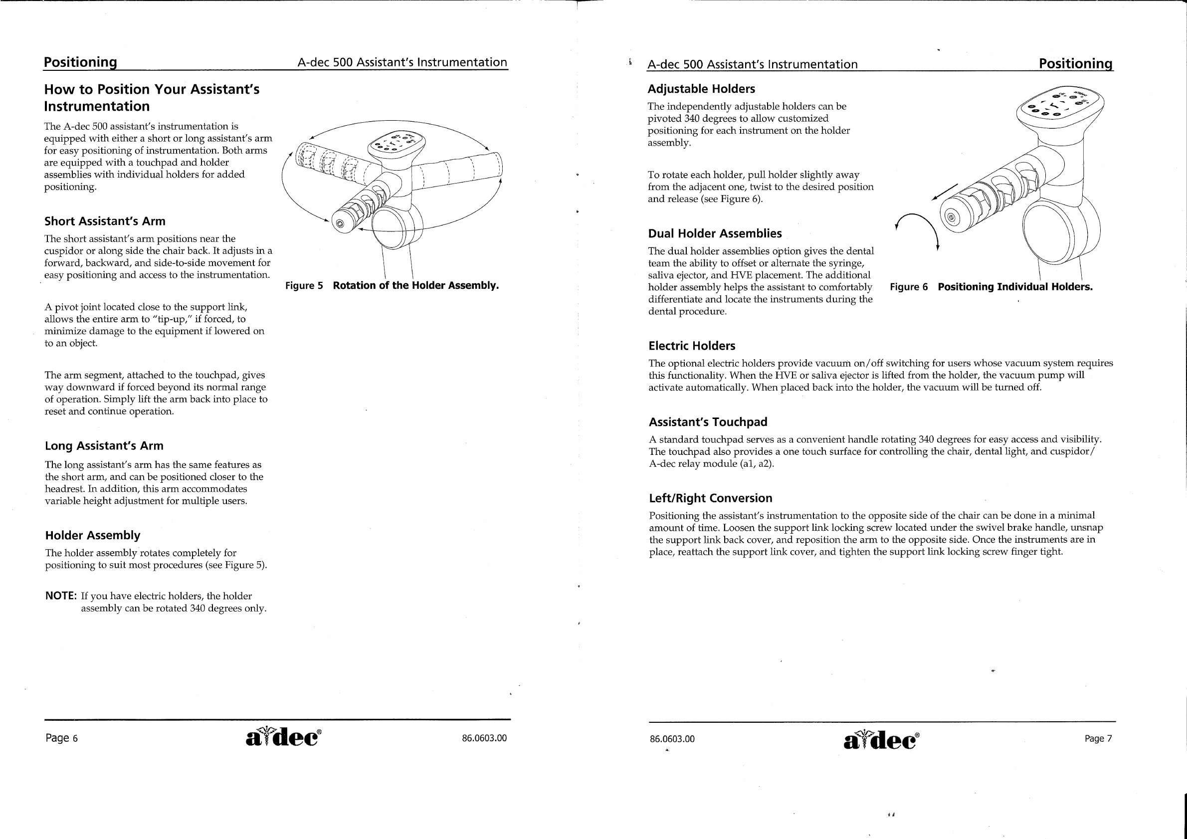
Figure
5
Rotation
of
the
Holder
Assembly.
A
pivot
joint
located
close
to
the
support
link,
allows
the
entire
arm
to
“tip-up,”
if
forced,
to
minimize
damage
to
the
equipment
if
lowered
on
to
an
object.
The
arm
segment,
attached
to
the
touchpad,
gives
way
downward
if
forced
beyond
its
normal
range
of
operation.
Simply
lift
the
arm
back
into
place
to
reset
and
continue
operation.
Long
Assistant's
Arm
The
long
assistant’s
arm
has
the
same
features
as
the
short
arm,
and
can
be
positioned
closer
to
the
headrest.
In
addition,
this
arm
accommodates
variable
height
adjustment
for
multiple
users.
Holder
Assembly
The
holder
assembly
rotates
completely
for
positioning
to
suit
most
procedures
(see
Figure
5).
NOTE:
If
you
have
electric
holders,
the
holder
assembly
can
be
rotated
340
degrees
only.
A-dec
500
Assistant’s
Instrumentation
Positioning
i
Page
6
sa
dec
86.0603.00
Adjustable
Holders
The
independently
adjustable
holders
can
be
pivoted
340
degrees
to
allow
customized
positioning
for
each
instrument
on
the
holder
assembly.
To
rotate
each
holder,
pull
holder
slightly
away
from
the
adjacent
one,
twist
to
the
desired
position
and
release
(see
Figure
6).
Dual
Holder
Assemblies
The
dual
holder
assemblies
option
gives
the
dental
team
the
ability
to
offset
or
alternate
the
syringe,
saliva
ejector,
and
HVE
placement.
The
additional
holder
assembly
helps
the
assistant
to
comfortably
Figure
6
Positioning
Individual
Holders.
differentiate
and
locate
the
instruments
during
the
dental
procedure.
Electric
Holders
The
optional
electric
holders
provide
vacuum
on/off
switching
for
users
whose
vacuum
system
requires
this
functionality.
When
the
HVE
or
saliva
ejector
is
lifted
from
the
holder,
the
vacuum
pump
will
activate
automatically.
When
placed back
into
the
holder,
the
vacuum
will
be
turned
off.
Assistant's
Touchpad
A
standard
touchpad
serves
as
a
convenient
handle
rotating
340
degrees
for
easy
access
and
visibility.
The
touchpad
also
provides
a
one
touch
surface
for
controlling
the
chair,
dental
light,
and
cuspidor/
A-dec
relay
module
(a1,
a2).
Left/Right
Conversion
Positioning
the
assistant’s
instrumentation
to
the
opposite
side
of
the
chair
can
be
done
in
a
minimal
amount
of
time.
Loosen
the
support
link
locking
screw
located
under
the
swivel
brake
handle,
unsnap
the
support
link
back
cover,
and
reposition
the
arm
to
the
opposite
side.
Once
the
instruments
are
in
place,
reattach
the
support
link
cover,
and
tighten
the
support
link
locking
screw
finger
tight.
i
$
θες
86.0603.00
a
Le
dec
|
Раде
7
#4
Touchpad
A-dec
500
Assistant’s
Instrumentation
How
to
Operate
Your
Standard
Touchpad
Manual
Chair
Controls
The
Base
function
controls
chair
lift,
or
vertical
movement.
To
raise
the
chair,
press
the
up
arrow.
To
lower
the
chair,
press
the
down
arrow.
Hold
down
the
arrow
until
the
chair
reaches
the
desired
height,
then
release
it.
The
Back
function
controls
the
chair
back.
To
raise
the
chair
back, press
the
right
arrow.
To
lower
the
chair
back,
press
the
left
arrow.
Hold
down
the
button
until
the
chair
back
reaches
the
desired
position,
then
release
it.
Program
Button
Use
the
Program
button
located
in
between
the
arrows
on
the
touchpad
to
save
the
settings
for
chair
positions
and
cuspidor
cup
fill
and
bowl
rinse
times.
Position
0
(Entry/Exit)
Pressing
Entry/Exit
(Position
0)
sends
the
chair
to
a
preset
entry/exit
position.
Positions
1
and
2
Pressing
Position
1
or
2
on
the
touchpad
sends
the
chair
base
and
back
to
a
preset
position.
Pressing
this
position
Causes
this
action...
Chair
base
and
back
move
to
Entry/Exit
(0)
|
me
preset
entry/exit
position.
Chair
moves
to
a
programmed
Position
1
or
2
. , ,
operating
position.
Chair
back
moves
to
an
Position
3
a
x-ray /rinse position.
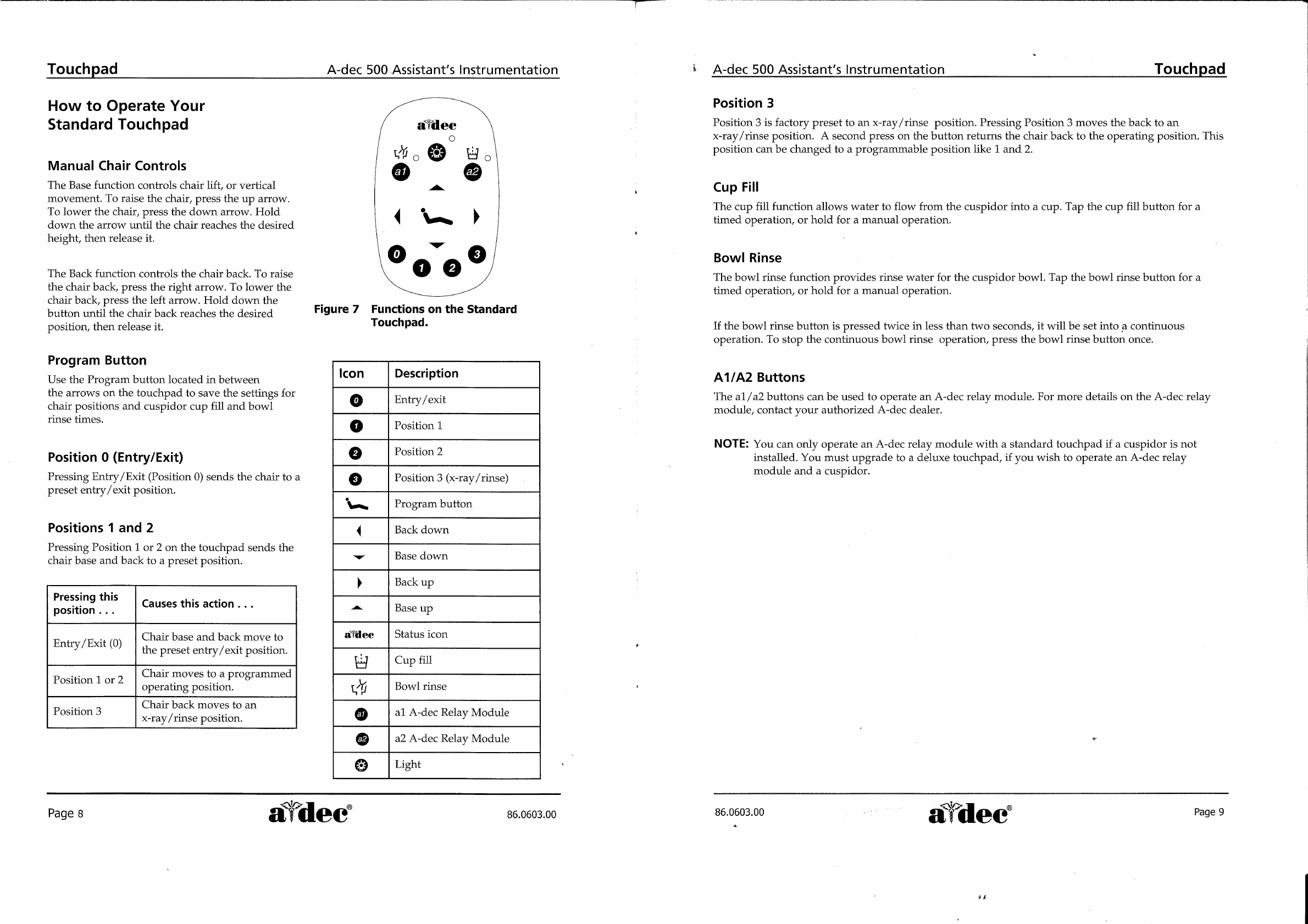
Figure
7
Functions
on
the
Standard
Touchpad.
Icon
Description
Entry
/exit
Position
1
Position
2
Position
3
(x-ray
/rinse)
Program
button
Back
down
Base
down
Back
up
„|-|
|
fooeeo
Base
up
afdec
Status
icon
Cup
fill
vi
Bowl
rinse
al
A-dec
Relay
Module
a2
A-dec
Relay
Module
61616
Light
Page
8
aldec
86.0603.00
A-dec
500
Assistant’s
Instrumentation
|
Touchpad
Position
3
Position
3
is
factory
preset
to
an
x-ray/rinse
position.
Pressing
Position
3
moves
the
back
to
an
x-ray/rinse
position.
À
second
press
on
the
button
returns
the
chair
back
to
the
operating
position.
This
position
can
be
changed
to
a
programmable
position
like
1
and
2.
Cup
Fill
The
cup
fill
function
allows
water
to
flow
from
the
cuspidor
into
a
cup.
Tap
the
cup
fill
button
for
a
timed
operation,
or
hold
for
a
manual
operation.
Bowl
Rinse
The
bowl
rinse
function
provides
rinse
water
for
the
cuspidor
bowl.
Tap
the
bowl
rinse
button
for
a
timed
operation,
or
hold
for
a
manual
operation.
If
the
bowl
rinse
button
is
pressed
twice
in
less
than
two
seconds,
it
will
be
set
into
a
continuous
operation.
To
stop
the
continuous
bowl
rinse
operation,
press
the
bow]
rinse
button
once.
A1/A2
Buttons
The
a1/a2
buttons
can
be
used
to
operate
an
A-dec
relay
module.
For
more
details
on
the
A-dec
relay
module,
contact
your
authorized
A-dec
dealer.
NOTE:
You
can
only
operate
an
A-dec
relay
module
with
a
standard
touchpad
if
a
cuspidor
is
not
installed.
You
must
upgrade
to
a
deluxe
touchpad,
if
you
wish
to
operate
an
A-dec
relay
module
and
a
cuspidor.
86.0603.00
Lee
에어
are
A.
kd
"dec
때

Touchpad
A-dec
500
Assistant's
Instrumentation
Dental
Light
The
dental
light
button
on
the
touchpad
works
as
a
three-way
switch
allowing
you
to
turn
the
dental
light
on
or
off
from
either
the
touchpad
or
the
dental
light.
A
quick
press
on
the
button
allows
you
to
toggle
between
three
intensity
settings,
depending
on
the
location
of
the
dental
light’s
intensity
switch.
The
dental
light
can
be
toggled
between
composite
and
medium
intensity
settings
or
composite
and
high
intensity
settings.
When
the
dental
light
is
in
the
composite
setting,
the
indicator
light
next
to
the
button
flashes.
The
dental
light
also
has
an
auto
on/off
feature.
When
using
a
programmed
chair
position
(1
or
2),
the
dental
light
will
come
on
when
the
chair
reaches
an
operating
position.
The
dental
light
will
turn
off
automatically
when
Position
0
(entry/exit)
or
Position
3
(x-ray/rinse)
is
pressed.
NOTE:
If
Position
3
has
been
reprogrammed
to
a
programmable
position,
the
dental
light
will
not
turn
on/off
when
Position
3
is
pressed.
How
to
Disable Factory
Preset
Functions
There
are
two
factory
preset
options
that
can
be
turned
on
or
off
from
the
standard
touchpad.
Dental
Light
(auto
on/off)
Auto
On/Off
setting
can
be
turned
off
by
pressing
and
holding
the
Program
button
and
then
the
Light
button
together
for
three
seconds.
One
beep
will
confirm
that
the
factory
preset
has
been
turned
off.
To
return
to
the
factory
preset
repeat
steps.
Three
beeps
will
confirm
that
the
auto
on/off
function
is
on.
Position
3
(x-ray/rinse)
Position
3
can
be
toggled
from
the
x-ray/rinse
position
to
a
programmed
position.
To
program
Position
3,
press
Program
and
then
press
and
hold
Position
3
together
for
three
seconds.
One
beep
confirms
that
the
position
can
be
programmed.
To
return
to
the
x-ray/rinse
position,
repeat
steps.
Three
beeps
confirms
that
the
x-ray/rinse
function
is
on.
4
Page
10
a
dec
86.0603.00
A-dec
500
Assistant's
Instrumentation
Care
Instructions
Touch
and
Transfer
Surfaces
Touch
surfaces
are
those
areas
that
require
contact
and
become
potential
cross-contamination
points
during
dental
procedures.
The
minimum
touch
surface
locations
on
A-dec
500
products
include
the
touchpad(s),
control
head
brake
handles,
and
dental
light
handles
and
switches.
Transfer
surfaces
are
those
surfaces
that
are
contaminated
by
contact
with
instruments
and
other
inanimate
objects.
The
primary
transfer
surfaces
on
the
A-dec
500
product
include
traditional
holders,
Continental”
instrument
pad,
and
trays.
A-dec
recommends
barrier
protection
for
all
applicable
touch
and
transfer
surfaces.
When
used,
barriers
must
be
FDA
market-cleared
barrier
plastic.
Cover-All™
barrier
film
or
any
other
FDA
market-cleared
barrier
film
is
suitable
for
this
application.
Refer
to
your
national
regulatory
authorities
for
barrier
recommendations
specific
to
your
locale.
Barrier
plastics
should
be
removed
and
discarded
after
each
patient
treatment.
For
touch
and
transfer
surfaces
where
barrier
protection
is
not
applicable
or
when
barriers
are
compromised,
please
refer
to
A-dec’s
Equipment
Asepsis
Owner’s
Guide
(P/N
85.0696.00)
for
recommendations
on
proper
cleaning
and
chemical
disinfection.
Heat
Sterilization
High
volume
evacuators
(HVE),
saliva
ejectors
(SE),
and
air/water
syringes
should
be
steam
autoclaved
between
patients.
The
following
protocol
should
be
followed:
HVE
—
steam
autoclave
at
134°C
(273°F),
6
minutes
holding
time
SE
—
steam
autoclave
at
134°C
(273°F),
6
minutes
holding
time
Air
/Water
Syringe
-
steam
autoclave
at
134°C
(273°F),
4
minutes
holding
time
Each
handheld
device
with
air
and
water
lines
should
be
discharged
for
20-30
seconds
between
each
patient
to
reduce
the
chance
of
cross-contamination
as
a
result
of
potential
bio-burden
retraction.
Specifications
Minimum
air,
water
and
vacuum
service
requirements
for
proper
unit
operation:
Air:
2.50
cfm
(70.80
1/min)
at
80
psi
(551
kPa).
Water:
1.50
gpm
(5.68
1/min)
at
40
psi
(276
kPa).
Vacuum:
12
cfm
(339.84
1/min)
at
8
inches
of
mercury
(27
kPa).
Specifications
are
subject
to
change
without
notice.
Ne
86.0603.00
a
dee
Page
11
À.
sê

Conclusion
Thank
you
for
taking
the
time
to
use
the
A-dec
500
Assistant’s
Instrumentation
Owner's
Guide.
We
would
appreciate
any
feedback
or
comments
you
have
about
this
document.
Please
mail,
email
or
phone
us
with
your
comments.
You
can
reach
us
at:
A-dec
Inc.
Technical
Communications
Department
2601
Crestview
Drive
Newberg, OR
97132
Reach
us
by
phone
at:1-800-547-1883
email:
website:
www.a-dec.com
si
aye
dee
A-dec
Inc.
2601
Crestview
Drive
Newberg,
OR
97132
USA
Tel:
1-800-547-1883
within
USA/Canada
Tel:
1-503-538-7478
outside
USA/Canada
www.a-dec.
biz
A-dec
International
Inc.
2601
Crestview
Drive
Newberg,
OR
97132
USA
Tel:
1-503-538-9471
www.a-dec.biz
A-dec
United
Kingdom
Austin
House,
11
Liberty
Way
Nuneaton,
Warwickshire
CV11
6RZ
England
Tel:
0800
ADECUK
(233285)
within
UK
Tel:
44
24
7635
0901
outside
UK
www.a-dec.co.uk
A-dec
Australia
41-43
Bowden
Street
Alexandria
NSW
2015
Australia
Tel:
61
(0)2
9699
4600
www.a-dec.com.au
86.0603.00
2004-1
Rev
A
(04123.13)
©A-dec
Inc.
2004
All
rights
reserved
This manual suits for next models
1
Table of contents
Other Adec Dental Equipment manuals


Popular Dental Equipment manuals by other brands

Heraeus
Heraeus iBond Total Etch Instructions for use

KaVo
KaVo INTRAmatic contra-angle 20 ES Instructions for use

EMS
EMS FT-188 Operation instructions

BG Light
BG Light BLUEDENT XPRESS cordless Operating instructions manual

Jordco
Jordco ENDORING II Instructions for use

Miele
Miele A 317 operating instructions

Schuler Dental
Schuler Dental S-U-AURO-KULI operating instructions

EKOM
EKOM DO 2.1 Installation, operation and maintanance manual

vita
vita VITA FDS operating manual

KERR
KERR SonicFill Instructions for use

DENTAURUM
DENTAURUM tiologic Instructions for use

HAGER WERKEN
HAGER WERKEN PRAXIPOL PS II Instructions for use


