ADEEPT AWR-A User manual


01

02

03
04

05

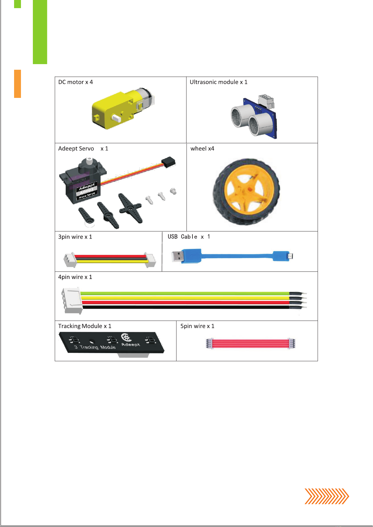
Take out the plates we will use.
Take out the car acrylic plates,
peel off the films.
Peel off the protective film on
the two sides of the plates.
Car Assembly.
06
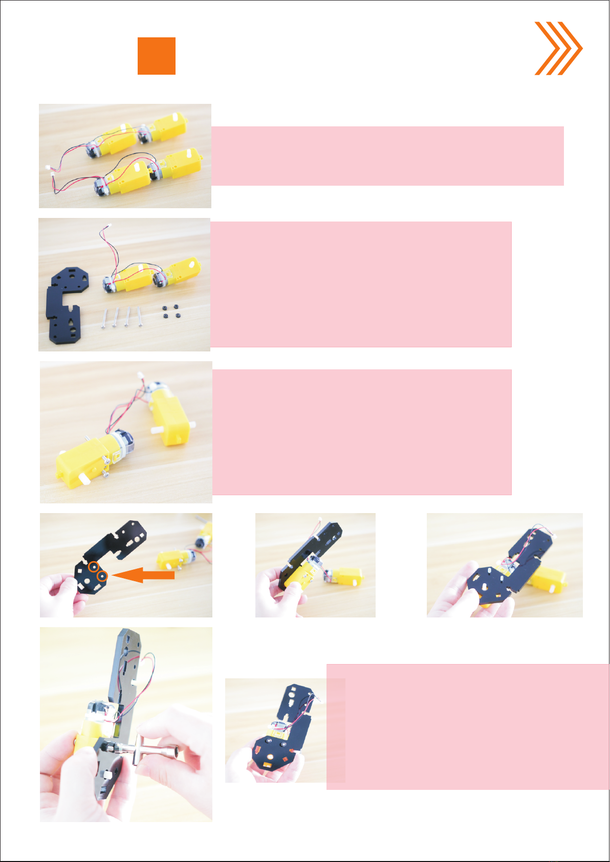
Take out two sets of motors (four motors one set),
pay attention not to break the wire connected to
the motor, handle gently.
First we take out the materials we need
according to the picture on the left:
1x set of motors
1x A01 acrylic plate
4x silver M3*30 screw
4x M3 nut
Pass two silver M3*30 screws from the
protruding surface through the fixing
hole of the motor.Note: First install the
motor welded with four wires.
Use the cross wrench to screw the
M3 nut onto the M3*30 screw.
Note that the screw can't be too tight.
If the M3 nut is tightened too much,
it will not be rotated after the motor
is energized.
Motor Part assembly.
07

On the left is an installation drawings
of one assembled set of motor.
Note: The M3*30 screw cap is on the
protruding face.
Assemble another part according to the above
method. Note that the motor needs to be installed
on the other side of the acrylic plate. Two sets of
motors are symmetrically mounted.
Use the cross wrench to fix two M3 nuts
to two M3*30 screws.Note that the screw
cannot be tightened too much.
Next pass two M3*30 screws through
the other motor.
08
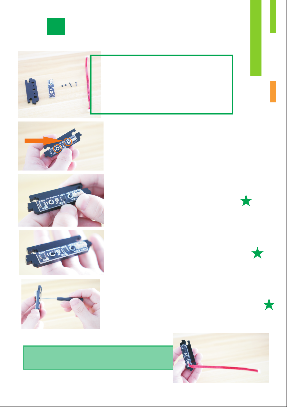
Attach the 3-CH Tracking Module to A02 as shown
in the figure. Note that the direction of the 5Pin
wire interface is to the right. If it is to the left,
the car tracking function will not work properly.
Pass two black M2*10 screws through the
two holes as shown.
Screw two black M2 nuts onto the M2 screw.
Use the small screwdriver to tighten the screws.
Connect the 5Pin wire to the
3-CH Tracking Module.
Tracking Module assembly.
Materials needed to assemble
the tracking module:
1x A02 acrylic plate
1x 3-CH Tracking Module
2x black M2*10 screws
2x black M2 nut
1x 5Pin wire
09
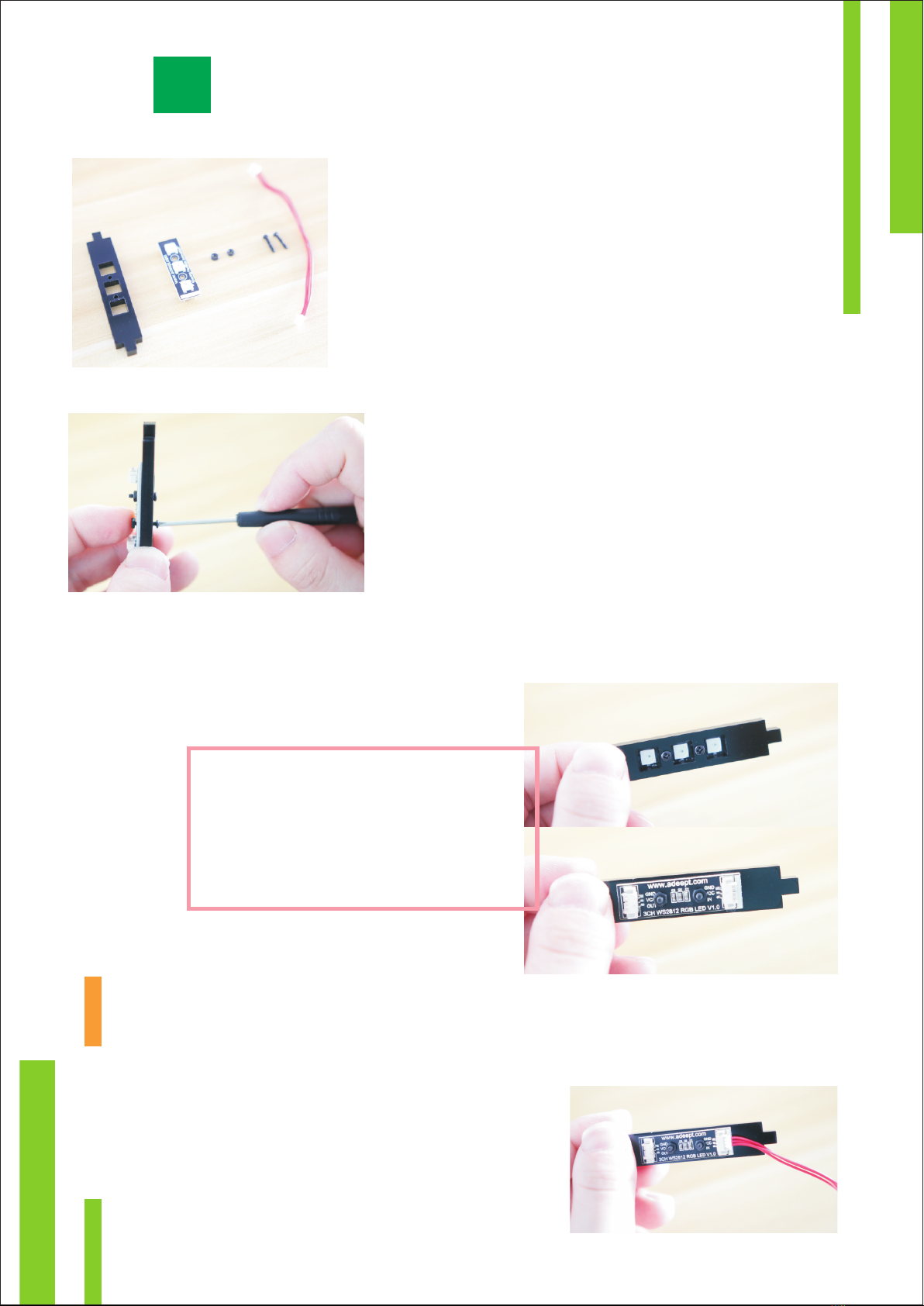
Materials needed to assemble the
WS2812 RGB LED:
1x A03 acrylic plate
1x 3CH WS2812 RGB LED
2x black M2*10 screws
2x black M2 nut
1x 3Pin wire
Attach the WS2812 to the acrylic plate.
Pass two black M2*10 screws through
the acrylic plate and the WS2812 module,
and screw two black M2 nuts into the
other end. Use the small screwdriver to
tighten the screws.
Connect the 3Pin wire to the "IN" connector.
Note that it is the one with white lines on the
3CH Ws2812 RGB LED. If connected wrong,
WS2812 will not work properly.
Ws2812 RGB LED Assembly.
Front and back after screwing.
10

Materials needed to assemble the car base A04:
1x A04 acrylic plate
2x silver M2.5*8 screws
2x M2.5*6+6 copper standoff
Pass two silver M2.5*8 screws through
the two holes on the acrylic plate.
Screw the two M2.5*6+6 copper standoffs
onto the M2.5*8 screws as shown in the figure.
Pay attention to the position of the copper
standoffs. If the copper standoffs are mounted
on the other side of the acrylic plate, the
subsequent installation of Adeept Smart
Hub will fail.
Materials needed to assemble the battery holder:
1x A04 acrylic plate
1x 16850 battery holder
2x silver flat head M3*10 screws
2x black M3 nut
Fix the battery holder on the A04 acrylic
plate as shown in the figure. Pay attention
to the wiring position of the battery holder.
If the battery holder is installed reversely,
the wiring will not be able to connect to the
power connector of Adeept Smart Hub.
Car base Assembly.
11

Use the cross wrench to fix the black M3
nut to the silver flat head screw M3 * 10.
Note that the screws here should be
tightened to prevent them loosening
and the battery holder to fall.
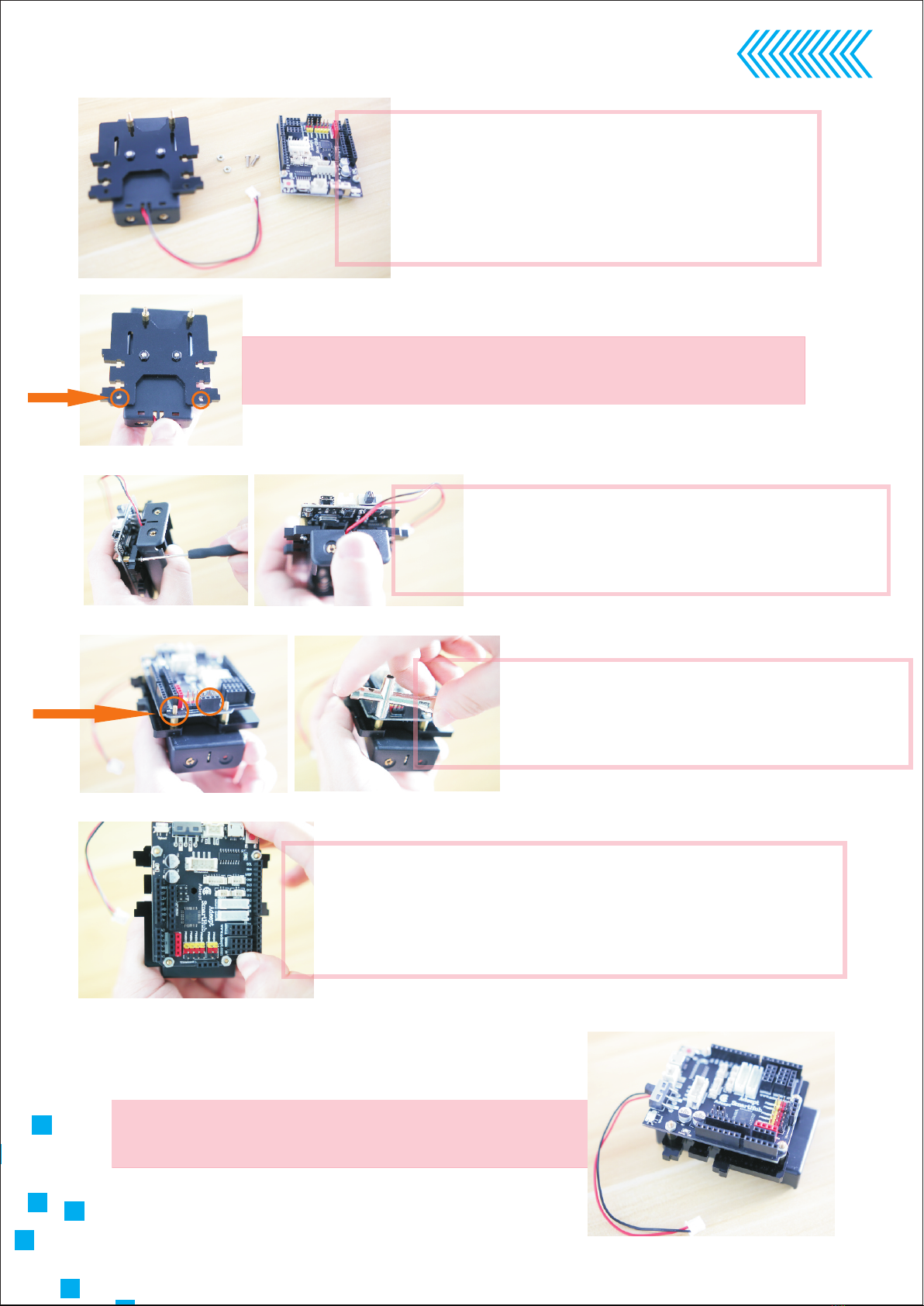
Materials needed to assemble the
Adeept Smart Hub:
1x Adeept Smart Hub
2x silver M2.5 nut
2x M2.5*6+6 copper standoff
Fix the copper standoff in these two
positioning holes.
Pass the M2.6*6+6 copper standoff
through the positioning hole as
shown in the figure, fix the other
end with silver M2.5 nut.
On the right is the effect
after assembling.
12
The car base after assembling is as shown.
Pass the M2.5*8 screw through the A04 acrylic plate.
Materials needed to assemble the base:
1x A04 acrylic plate
2x silver M2.5 nut
2x silver M2.5*8 screws
1x Adeept Smart Hub
Use the small screws to screw two
M2.5 screws to two M2.5*6+6 copper
standoffs.
Use the cross wrench to fix two silver
M2.5 nuts to the M2.5*6+6 copper
standoffs as shown.
Note: If the silver M2.5 nut is not easily screwed
onto the M2.5*6+6 copper standoff, push the
black 4Pin female header of the P7.
13

Place the A02 acrylic plate on the
via of the A01 acrylic plate as shown.
Pass the black M3*12 screw
through the A01 acrylic plate
and tighten the M3*12 screw
with the large screwdriver.
Motor And Tracking Module Assembly.
Use the small screwdriver to place
the black M3 nut into the position
as shown.
Materials needed to assemble
the motor and tracking module:
1x A01 acrylic plate
1x black M3*12 screw
1x black M3 nut
1x A02 acrylic plate
On the right is the real product
after assembling.
14

Fix The Base.
Use the small screwdriver to place the two black M3
nuts into the position as shown.Note: Be careful not
to let the M3 nut slip off the A04 acrylic plate.
Fix A04 to this position on the A01 acrylic
plate as shown.
Use the large screwdriver to tighten the
M3*12 screws.
On the right is the effect after assembling.
Materials needed to fix the base:
1x A01 and A02 acrylic plate
1 x A 0 4 a c r y l i c p l a t e
2 x b l a c k M 3 *1 2 s c r e w
2x black M3 nut
Place two black M3*12 screws into the position
as shown.
15

Car Base Assembly.
Materials needed to assemble the car base:
1x A01 and A04 base
1x A02 acrylic plate
1x A05 acrylic plate
1x A06 acrylic plate
1x A01 acrylic plate
The effect diagram when get to this step.
Place the A06 acrylic plate
on the A01 acrylic plate as
shown.
Place A05 on A01 acrylic plate as shown.
Place A03 acrylic plate on A01
acrylic plate as shown.
16

Fix the A01 acrylic plate to the car base.
On the right is the effect after assembling.
As shown, use the small screwdriver to
place the black M3 nut on the screw hole
on the A02 acrylic plate.
Use the small screwdriver to place
the two black M3 nuts in the position
as shown.
Pass the black M3*12 screw through
the A01 acrylic plate and use the large
screwdriver to tighten the M3*12 scre
Pass two black M3*12 screws
through the A01 acrylic plate
and tighten the M3*12 screws
with the large screwdriver.
17

Ultrasonic Module Assembly.
Install the ultrasonic module on
A07 acrylic plate.
Connect the 4Pin wire with ultrasonic module.
Materials needed to assemble
the servo module:
1x Adeept AD002 Servo
2x black M2*10 screw
2x black M2 nut
1x A08 acrylic plate
Materials needed to assemble
the ultrasonic module:
1x A07 acrylic plate
4x silver M1.4*6 self-tapping screw
1x ultrasonic module
1x 4Pin wire
Install the servo on the A08 acrylic plate as
shown in the figure, pass two black M2*10
screws through the A08 acrylic plate.
Install four silver M1.4*6 self-tapping screws
into the ultrasonic positioning holes and use
the small screwdriver to screw the screws vertically
into the A07 acrylic plate.Note: if you find that
A07 is difficult to screw in, you can try to turn over
the A07 acrylic plate and screw it in again.
18

Screw two black M2 nuts onto the two
M2*10 screws and tighten the M2*10
screws with the small screwdriver.
Materials needed to assemble the head of the car:
1x A09 acrylic plate
1x ultrasonic module
1x Ad002 servo module
6x black M3*12 screw
3x black M3*25 nylon column
Pass the wires of the servo and ultrasonic
module through the hole of A08 acrylic plate.
Mount the ultrasonic module on the A08 acrylic plate.
Screw three black M3*12 screws through
the A08 acrylic plate and screw three black
M3*25 nylon columns onto the M3*12
screws as shown.
Cover the A09 acrylic plate on the A08 and the
ultrasonic module.
19
Table of contents
Other ADEEPT Educational Equipment manuals


Popular Educational Equipment manuals by other brands


Fisher-Price
Fisher-Price R2157 manual

sparkfun
sparkfun Weevil Eye Information & Instructions

John Lewis
John Lewis Illuminated globe quick start guide

Aircatglobal
Aircatglobal VirtualFly VF-G1000 user manual

Saltillo
Saltillo ALT-Chat Quick reference guide

adafruit learning system
adafruit learning system MatrixPortal M4 manual