K5623V1 4/01
ADEM CO LIM ITED W ARRANTY
Alarm Device Manufacturing Company,a Division of PittwayCorporation,and its divisions,
subsidiaries and affiliates ("Seller"),165 Eileen Way,Syosset,New York 11791,warrants its
products to be in conformancewith its ow n plans and specificationsand to be free from defects
in materials and workm anship undernormaluse and service for24 m onthsfrom the date stam p
controlon the productor,forproducts nothaving an Ademcodate stam p,for12 m onths from
date of original purchase unless the installation instructions or catalog sets forth a shorter
period, in w hich case the shorter period shallapply. Seller's obligation shallbe limited to
repairing orreplacing,atits option,free ofcharge formaterials orlabor,any productwhich is
proved not in com pliance w ith Seller's specifications or proves defective in m aterials or
workm anship undernormaluse and service.Seller shallhave no obligation underthis Limited
Warranty or otherwise ifthe productis altered or improperly repaired or serviced by anyone
otherthan Ademcofactory service.Forwarranty service,return producttransportation prepaid,
to AdemcoFactory Service,165 Eileen Way,S yosset,New York 11791.
THERE ARENO W ARRANTIES,EXPRESS OR IMPLIED,OFM ERCHANTABILITY,OR
FITNESS FO R A PARTICULAR PURPOSE OR OTHERW ISE, WHICH EXTEND
BEYOND THE DESCRIPTION ON THE FACE HEREOF.IN NO CASE SHALL SELLER
BE LIABLE TO ANYONE FOR ANY CONSEQUENTIAL OR INCIDENTAL DAM AGES
FOR BREACH OF THIS OR ANY OTHER W ARRANTY,EXPRESS OR IMPLIED,OR
UPON ANY OTHER BASIS O F LIABILITY W HATSOEVER,EVEN IF THE LOSS OR
DAM AGEIS CAUSED BY THE SELLER'S OW N NEGLIGENCEOR FAULT.
Seller does notrepresent thatthe products itsells maynotbe com prom ised or circum vented;
thatthe products willpreventany personal injury orproperty loss by burglary,robbery,fire or
otherwise; or that the products w ill in allcases provide adequate w arning or protection.
Custom erunderstands thata properly installed and maintained alarm mayonly reduce the risk
ofa burglary,robbery,fire orotherevents occurring withoutproviding an alarm,butitis not
insurance or a guarantee thatsuch w illnotoccur or thatthere w illbe no personal injury or
property loss as a result.CONSEQUENTLY,SELLER SH A LL HAVE NO LIABILITY FO R
ANY PERSONAL INJURY,PROPERTY DAMAGE OR OTHER LOSS BASED ON A
CLAIM THE PRODUCT FAILED TO GIVE W ARNING.HOW EVER,IF SELLER IS
HELD LIABLE, W HETHER DIRECTLY OR INDIRECTLY, FOR ANY LOSS OR
DAM AGE ARISING UNDER THIS LIMITED W ARRANTY OR OTHERW ISE,
REGARDLESSOFCAUSE OR ORIGIN,SELLER'S MAXIMUM LIABILITY SH A LL NOT
IN ANY CASE EXCEED THE PURCHASE PRICE OFTHE PRODUCT,WHICH SHALL
BE THE COM PLETE AND EXCLUSIVE REMEDY AGAINST SELLER.This w arranty
replaces any previous warranties and is the only warranty madeby Seller on this product.No
increase or alteration, written or verbal,of the obligations of this L imited W arranty is
authorized.
FCC NOTICE
FCC ID: CFS 8DL 5817CB
This device complies with Part 15 of FCC rules. Operation is subject to the
following two conditions: (1) This device may not cause harmful interference. (2)
This device must accept any interference received, including interference that may
cause undesired operation.
ALARM DEVICE MANUFACTURING COMPANY
A DIVISION OF PITTWAY CORPORATION
165 Eileen Way, Syosset, New York 11791
Copyright © 2000 PITTWAY CORPORATION
¬.895694,l#
®
K5623V1 4/01
5817CB
WIRELESS COMMERCIAL
HOUSEHOLD TRANSMITTER
INSTALLATION INSTRUCTIONS
GENERAL INFORMATION
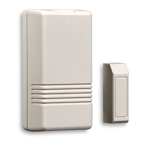
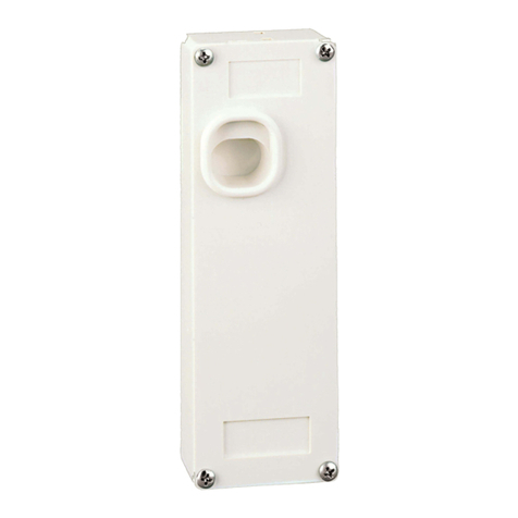
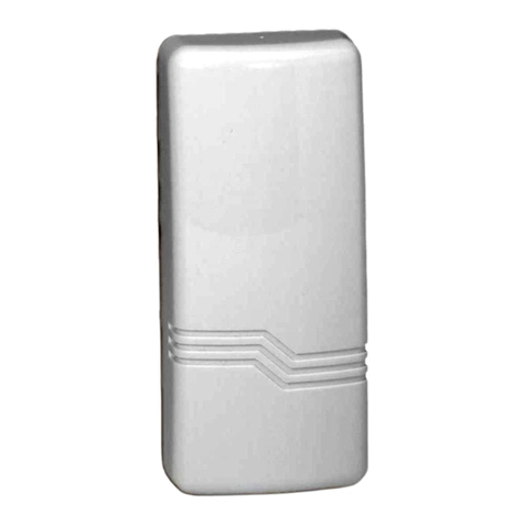
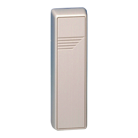
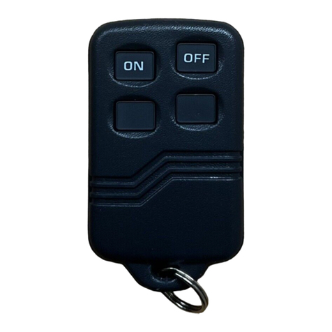
The 5817CB is a universal contact-monitoring transmitter that can be used with household
and commercial fire and burglary-initiating devices such as door/window contacts, motion
and glassbreak detectors, sprinkler water flow switches, tamper switches, post indicator
valves, manual pull stations, and remote duct detectors. Upon activation, it emits an RF
signal to a control panel that sends a burglary or fire alarm to a central station. The 5817CB
has three unique input loops (zones). The first loop (primary loop) is supervised and typically
used for high-priority alarm reporting such as commercial fire or burglary. It requires a
470K ohm end-of-line resistor to be placed across the sensor. The second loop is the built-in,
normally closed reed switch (used in conjunction with a magnet, as described below). The
third loop is another normally closed household burglary loop. All three loops may be used. A
fourth (automatically enrolled) loop contains two tamper switches to protect the 5817CB
transmitter. A built-in cover tamper switch is activated when the cover is removed. A unit
tamper switch is activated if the unit is separated from its mounting plate.
The 5817CB has its own unique serial number permanently assigned during manufacture.
You must "enroll" this transmitter serial number in the control panel at some point prior to
its usage in the alarm system. Refer to the control panel's installation instructions for
further details. Note: During programming of the control panel, program the 5817CB
transmitter as Input Type "RF" (i.e., supervised RF) (mandatory for UL installations).
MOUNTING
For proper orientation of the unit in relation to its wall mounting plate and the loop wiring,
read all of this section before installing the unit. Before mounting the transmitter
permanently, conduct Go/No Go tests (see control's instructions) to verify adequate signal
strength from location. When a satisfactory location is found, remove the battery and proceed
with installation.
The following mounting instructions assume that the unit will be mounted as shown in the
diagrams. The unit may, however, be installed in any direction, as long as the relationship of
the unit to its mounting plate is maintained.
The mounting plate, installed as described below, enables easy removal of the unit for
servicing, should it become necessary.
1. Remove the transmitter's cover by inserting the flat blade of a small screwdriver into
the pry-off slot at the bottom end of the unit on the right side closest to the cover's
decorative ribs and twisting.
2. Disengage the supplied mounting plate from the unit by inserting the blade of a
small screwdriver into the mounting plate release hole (see Diagram 2) and pushing the
locking tab out (see Diagram 1). Slide the mounting plate downward along the case back.
Note: For this application, the alignment guide strip along one edge of the mounting
plate serves no function and may be broken away, if desired.
3. If concealed wiring is to be used, feed the wires through the concealed wiring entry
hole at one corner of the plate (surface wiring is mentioned in Step 5 below).
4. Install the mounting plate, with its case-holding posts pointing up, in the location
selected, as described in the control unit's installation instructions. Use the two flat-head
screws supplied. Note: To ensure proper operation of the unit's back tamper (when it is
separated from the mounting plate), the screws must be anchored to a wall stud or other
solid wood material.
5. If surface wiring is to be used, remove the knockout slot in the case back (located
across from loop 3 terminal block). Surface wiring should enter through this knocked
out space provided. Do not connect the wiring to the terminal block(s) yet.
www.PDF-Zoo.com


