Adesys SVL Series User manual

MEASURING - ALERTING - CONNECTING
EN
Manual SVL
Version 06-2019

Page 2Manual SVL 4G Weblogger
Adesys B.V. | Wateringen
Index
1 Introduction 3
1.1 Variants 3
1.2 Features of the SVL-series 3
1.3 Safety criteria 3
1.4 Checking the delivery 3
1.5 Environment 3
1.6 Warranty and repair 3
1.7 Liability 4
1.8 Identication 4
2 Connection 5
2.1 Positioning 5
2.2 Axingandremoval:DINrail 5
2.3 SIM card 5
2.4 Antenna 6
2.5 Power supply 6
2.5.1 SV-20 mains adapter 6
2.5.2 Power supply 6
2.6 Reset key 6
2.7 Ethernet 6
2.8 2G/4G connection 6
2.9 Inputs and outputs 7
3 SV-prog 7
3.1 Installation 7
3.2 Status screen 7
3.3 Call list 7
3.4 I/O 7
3.4.1 Input delay 7
3.4.2 Recovery report (idle) 8
3.4.3 System errors 8
3.5 Connections 8
3.5.1 Checkmyproces.com 8
3.5.2 Own server 8
3.5.2 Connection interval 8
3.6 System 8
3.6.1 Device 8
3.6.2 Ethernet 8
3.6.3 GSM and mobile data 8
3.6.4 Factory reset 9
4 Noticationprocedure 9
4.1 Noticationmessage 9
4.2 Noticationofstatuschanges 9
4.3 Noticationofmainspowerfailure 9
5 Output switching by SMS 10
6 Appendices 11
6.1 Led status indication 11
7.2 Technicalspecications 11

Page 3Manual SVL 4G Weblogger
Adesys B.V. | Wateringen
1 Introduction
ThismanualcoverstheSVLmoduleequippedwithrmwareversion1.0andhigher.TheSVLisanalarm
dialer and can be used to monitor processes and report alarms via SMS and E-mail.
1.1 Variants
TheSVLisavailableinmultiplevariants:
• The SVL with universal inputs and an output open collector;
• The SVL with universal inputs, output open collector and a relay output;
• The SVL with universal inputs, output open collector and a PT100 2-wire or 3-wire temperature sensor;
• The SVL with contact inputs and a PT100 2-wire or 3-wire temperature sensor.
1.2 FeaturesoftheSVL-series
• Checkmyproces.com.
• Congurabledelaytimes.
• Reporting of power failure.
• Periodicrestart(reset)oftheSVL(canbeswitchedonando).
• Ethernet interface UTP connection.
• SettingsandSMStextsarepermanentlystoredintheinternalashmemoryoftheSVL.
We recommend that you read the user manual carefully so that you can make optimal use of all SVL
options.
1.3 Safetycriteria
BeforeusingtheSVL,thereareseveralcriteriathattheusershouldmeet:
• TheSVLshouldbeinstalledinacontrolledenvironment(forreasonsofreprevention);
• The SVL should be supplied with power using a SELV-type power supply;
• ExternalEthernetshouldnotbeconnecteddirectlytoanSVL,butshouldbeconnectedviaan
overvoltage protection device;
• To reduce the probability of damage to the equipment, the SVL should be placed in an environment
protectedagainstelectrostaticdischarge(ESD);
• The SVL is intended for use as a modem or alarm dialer. The SVL is not intended for use as part of a
critical safety system in a critical process.
1.4 Checking the delivery
Check the packaging for damage. Contact your supplier immediately if the delivery is found to be
damaged or incomplete upon receipt.
The standard delivery includes:
• SVL module;
• Connection terminals;
• Ethernet cable;
• Quickstart SV-line.
Optional items include:
• Antenna and antenna cable (various models, including vandalism-proof antennas);
• Mains adapter 230 Vac/12 Vdc (item number SV-20).
1.5 Environment
This product contains materials that can harm the environment. For the sake of the environment, if the
product has to be replaced at the end of its service life please do not dispose of it through the household
waste. Please return the device to your supplier or hand it over to a designated depot.
1.6 Warrantyandrepair
AdésysperformsaseriesofextensivetestsoneachSVLbeforedispatch.ADÉSYSusesawarrantyperiod
of 1 year.
Warranty claims are invalidated if:
• Thedefectiscausedbygrossnegligenceorinexpertinstallation;
• Thedevicehasbeenopenedand/orrepairsormodicationshavebeenperformedwithoutthe
permission of adésys;
• It is found that the serial number has been removed or damaged.
Please get in touch with Adésys customer service if you have any questions regarding the warranty or
repairs.
Page 4Manual SVL 4G Weblogger
Adesys B.V. | Wateringen
1.7 Liability
Adésys accepts no liability for consequential loss in the event of the stagnation of the alarm. An alarm
dialerdoesnotprovidea100%guaranteeagainstdamage,itismerelyatooltopreventdamage.You
should therefore discuss the remaining risk with your insurer.
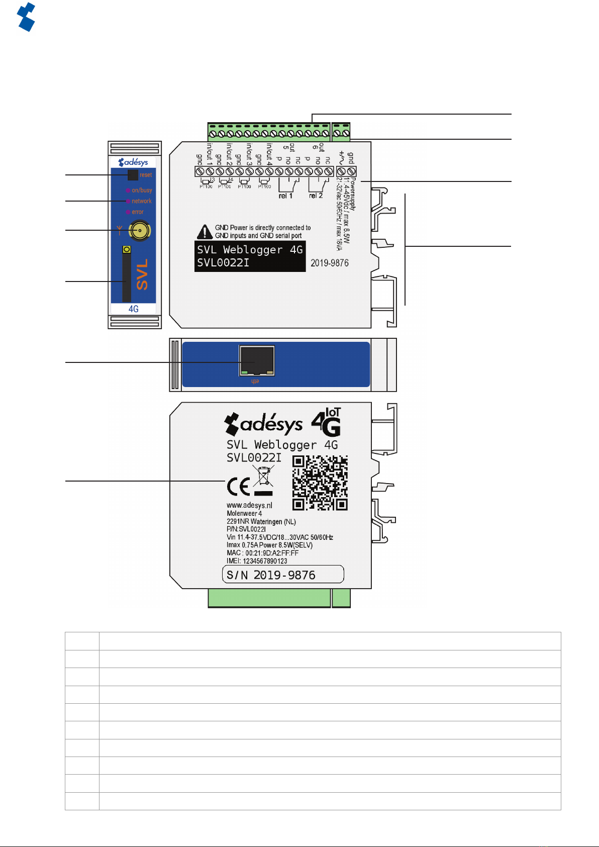
1.8 Identication
1 Reset button
2LEDstatusindicator:generalstatus(on/busy),antennalevel(network),errormessage(error)
3 Antenna connection type SMA female
4 SIM card holder
5 Ethernet connection
6 Information sticker
7 Input/output connection terminals
8 Supply voltage connection terminals
9 Connection sticker
10 DIN-railmountingclamp
Figure 1 Identication SVL
1
2
3
4
5
6
7
8
9
10
Page 5Manual SVL 4G Weblogger
Adesys B.V. | Wateringen
2 Connection
ToconnecttheSVLcorrectly,werecommendusingexclusivelyCamdenCTB922HE/#typeconnectors.
Measurementsmaybeaectedifotherconnectorsareused.
2.1 Positioning
PositiontheSVLwhereitisnotaectedbydirectsunlightorotherheatsources.Choosetheplaceof
installation such that moisture cannot penetrate the device. The SVL can be mounted onto the TS35 rail
without screws. The permitted ambient temperature range for the electronics is -20°C to +55°C.
The transmission power of the SVL’s internal GSM/4G module is higher than that of a standard mobile
phone.Undercertainconditionsthismayaectthefunctioningofsurroundingelectronicequipment.The
eectsdependuponthedistancebetweentheantennaandsurroundingequipment.
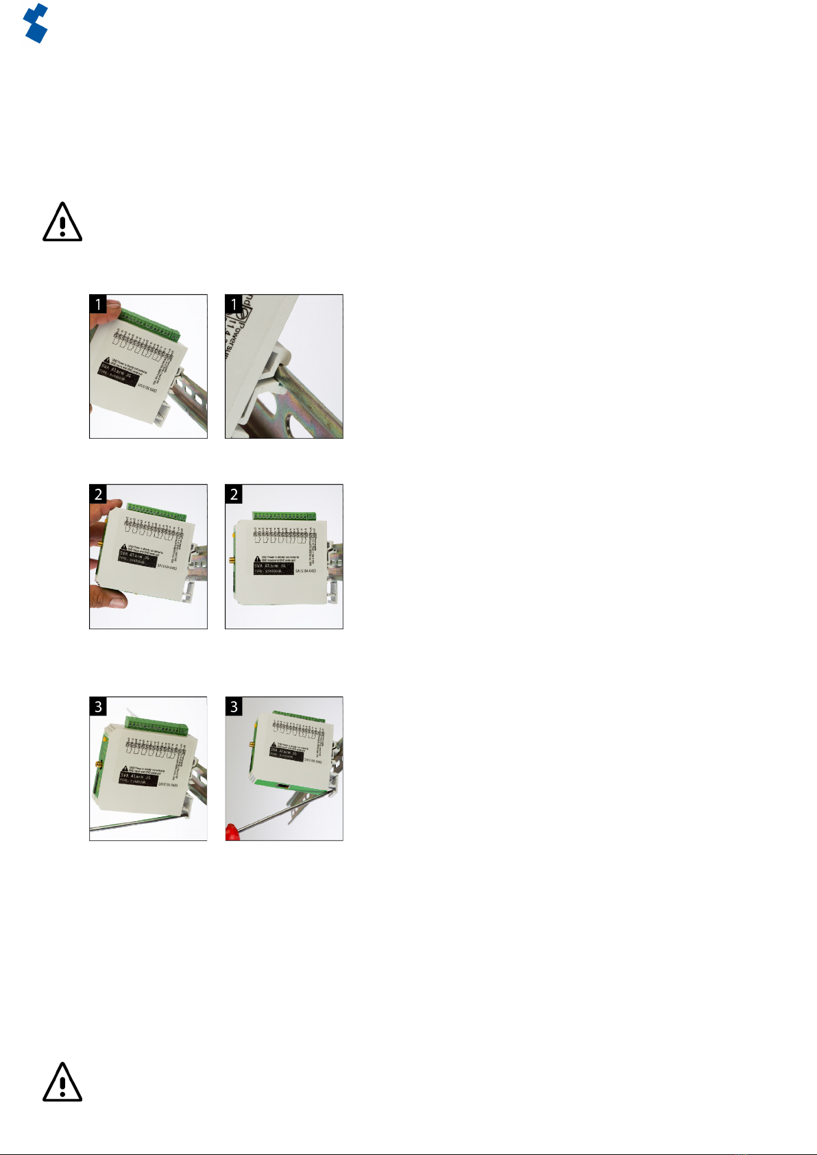
2.2 Axingandremoval:DINrail
TheSVLshouldbeaxedtoaDINrailbeforeconnection.
• PuttheSVLontotheDINrailatanangle[1].ItisimportantthattheSVL’sDINrailclipispositionedon
thetopoftheDINrail.
• TilttheSVLtoclipitintoplace[2].Thencheckwhetheritissecurelyseated.
TheSVLisremovedfromaDINrailasfollows.
• PlaceascrewdriverontheundersideoftheDINrailclip[3].Usethisasalever;afterapprox.3mmthe
SVLcanbetiltedtoreleaseitfromtheDINrail.
2.3 SIMcard
If the SIM card has a PIN code, this should be entered in the setup tool SV-prog. The required SIM card is
installedasfollows:
• SwitchtheSVLobydisconnectingthesupplyvoltage,thenpressandholdtheresetkeyfor8seconds
toswitchothedialer;
• TheSIMcardholderismadeaccessiblebypressingthebuttonnexttoitusingasharpobject.The
holder is then pushed outwards;
• Place the SIM card in the holder and slide this back into the SVL;
• Reconnect the supply voltage to switch the SVL on.
TheSVLshouldbecompletelyswitchedobeforetheSIMcardisinstalled.FittingorremovingtheSIM
card with the SVL switched on may damage the SIM card.

Page 6Manual SVL 4G Weblogger
Adesys B.V. | Wateringen
The use of a ‘Prepaid’ SIM card for dialling purposes is strongly discouraged. The mobile network cannot
automatically request the call credit, which means that this can be run down without anyone noticing,
resultinginoutgoingnoticationscomingtoastandstill.
2.4 Antenna
Connect the antenna cable to the SVL’s antenna connection. The antenna plus associated cable can be
obtainedfromAdésys.Theantennashouldbeaxedtoashighapointaspossibletoobtainthebest
possible range.
Afterinstallation,alwayschecktheeldstrengthoftheantennasignal(max.is5ashesoftheyellow
‘network’LED).Noticationofchangesinsignalstrengthwillalwaystakeplaceafteralongdelay(±30
seconds).Takethisintoaccountif,forexample,theantennaismoved.
2.5 Power supply
2.5.1 SV-20mainsadapter
A 230Vac/12Vdc mains adapter with item number SV-20 can be obtained as an option to supply power to
the SVL.
Whenttingtheterminalblocktothepowersupplycable,ensurethatthepolarityplus(+)andminus(-)is
correct.
Anextrapowersupplyfuseisnotnecessaryhere.
If the SVL is not supplied with power using the above-mentioned mains adapter, the connection
regulations in the section below apply.
2.5.2 Power supply
ConnecttheSVLtoaDCpowersupplyof12to46Vdc(atleast8.5W)oratransformerof20to35Vac.The
powersupplyinputoftheSVLisnotgalvanicallyisolatedfromtheotherconnections.TheGNDconnection
ofthepowersupplyconnectorisdirectlyconnectedinternallytotheGNDconnectionoftheinput
connector and the COM port.
If the SVL is connected to an application (process controller, PLC, computer, active sensor, etc.) without
galvanic isolation and the SVL is connected to the same power supply, there is a real chance of earth loops
and/or short circuits in this power supply.
2.6 Reset key
Theresetkeyhasthreefunctions:rstofall,itisusedtointerruptthealarm.Pressingthisbrieyendsthe
currentnotication;theSMSmessagesthathavenotyetbeensentarenotsent.
A second function of the reset key is to restart the dialer. The dialer can be restarted by holding this key
down for a period of 8 seconds. This only occurs if a power supply is connected.
Ifnopowersupplyisconnected,theresetkeyfunctionsasanobutton.Holdingthekeydownfora
periodof8secondsswitchesothedialer.
Statuses of inputs will not be stored in a permanent memory. If the supply voltage fails, and the built-in
supercap is entirely discharged, the contents of this memory is lost. If the SVL is restarted manually, this
status will also be reset. When the supply voltage is restored, the SVL behaves as if it is being started up
forthersttime.Thismeansthat:
• After the supply voltage has been restored, only active inputs are reported once again;
• No recovery message will be sent if the status of the input has been recovered during this power failure.
The fourth functionality is for when there is something wrong and there seem to be no connection. By
pushingtheresetkeyforadurationof3seconds,releasingit3secondsanddoingthis3timestheDHCP
willbeenabled.ByenablingtheDHCPitispossibletomakechangeswithSV-prog.
2.7 Ethernet
TheEthernetconnectioncanbeusedforanexternalconnection.ThisissetupintheSVL:seetheSV-prog
section. By default this is set up to connect to Checkmyproces.com.
2.8 2G/4G connection
To use the SVL with a 2G/4G connection, a SIM card with Internet subscription should be installed in the
SVL. It is important that the correct APN, APN user and APN password are entered, otherwise the SVL will

Page 7Manual SVL 4G Weblogger
Adesys B.V. | Wateringen
not be able to connect. This can be entered in SV-prog in the 2G/4G window.
TheSVLdoesnotprovideanoticationifsomethinggoeswrongwiththeAPN.Formoreinformation
about the APN, please contact your provider.
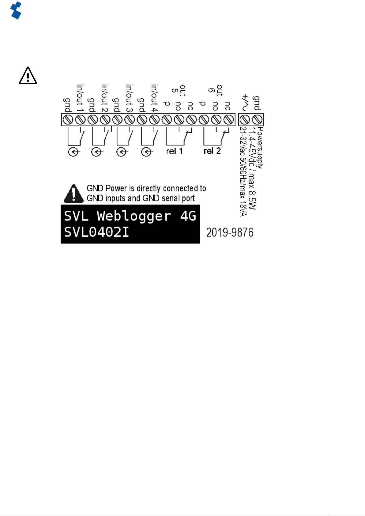
2.9 Inputsandoutputs
It is possible to connect several variants of inputs and outputs to the SVL, such as contact inputs, voltage
inputsdcandrelayoutputs.Whenconnectingdierentinputsitisimportanttolookcarefullyatthewiring
diagram. This can be found on the side of the SVL.
Inputsareprotectedagainst24VAC.However,theyarenotmeantforthedetectionormeasuringAC
signals.
3 SV-prog
3.1 Installation
SettinguptheSVLcanbedoneintwoways,thefullyadjustablewayoftheSV-progtoolandalimited
adjustablewayviaRemoteSetup.ForRemoteSetup,chapter3.5.1Checkmyprocess.comcanbe
consulted.
SV-prog is used to set up the SV series. This program can be downloaded free of charge from the Adésys
website(www.adesys.nl).Allsettingswillbestoredintheinternalashmemory.Itisnot possible to store
the settings on the SIM card!
SV-prog must be installed on your PC before it can be used. Follow the instructions displayed on your
screen during the installation process. As soon as the installation process is complete, start the program
via the shortcut or via the program menu in MS Windows.
Connect the SVL to a power source and connect the SVL to the PC using the Ethernet cable set supplied.
The SVL can be connected to the local network or directly to the PC.
As soon as the SVL has been switched on, the tool will display this in the overview after a few seconds
andtheSVLcanbeconguredbyclickingit.Whensearchdialersispressed,SV-progshowsallaccessible
dialers.
When SV-prog is not showing any dialers or when the error message ‘No ethernet cable’ is shown. There is
apossibilitythewrongnetworkadapterischosen.ByopeningSV-progandopeningthecongurationon
thetopleftsideitispossibletoadjustthenetworkadapter.
Terms used
ThetermsyouwillencounterinSV-progareexplainedbelow.
3.2 Statusscreen
ThestatusscreenprovidesyouwithinformationontheSVL.ExamplesofthisinformationaretheIMEI
code, the serial number, the MAC address and the current status of the inputs and alarms/errors.
3.3 Calllist
A call list is a group of contacts(SMS or E-mail) that can be coupled to the input to send an alarm message
or alarm recovery message. One to eight contacts can be programmed into a call list.
3.4 I/O
Inputs are displayed in this window. All inputs can be set up separately from one another. Settings can
also be established here for Mains Power Failure and System Errors.
Onecalllistcanbesetupforeachinput.Assoonasaninputbecomesactive,thenoticationprocedure
starts. The associated alarm message is sent to all set telephone numbers one after the other. This is
explainedfurtherintheNoticationProceduresection.
3.4.1 Inputdelay
Adelaycanbesetforthestatusnotication(activeandidlemessage)ininputdelay.Thismeansthe
statusnoticationwillnotbesentuntiltheinputhasbeenactivatedordeactivatedforlongerthanthis
period.Themaximumthatcanbesetis‘3600’seconds.
Ifaninputgoesbackintoidlemodeduringthedelaytime,thenoticationproceduredoesnotstart.

Page 8Manual SVL 4G Weblogger
Adesys B.V. | Wateringen
3.4.2 Recovery report (idle)
Ifdesired,arecoveryreportSMScanbesentaftertheinputgoesintoidlemode.Thedefaultsettingiso
evenifnothinghasbeenselected.Select‘Yes’toactivatethisnotication.Arecoveryreportwillalwaysbe
senttotheexternalserver.
3.4.3 System errors
VarioussystemerrorscanbedetectedbytheSVL.Noticationscanbesetupindividuallyforeacherror.
Dependingupontheerror,thisisdisplayedintheprogrammingtoolandanoticationissentviaSMS.By
defaultthenoticationofallsystemerrorsviaSMSisswitchedo.
3.5 Connections
Theterm‘connections’isusedtomeantheconnectiontoanexternalserver.WiththeSVLitispossibleto
make a connection to Checkmyproces.com or to a dedicated server.
3.5.1 Checkmyproces.com
Checkmyproces is a server on which the status of the SVL can be logged and is displayed via the cloud.
After logging in, SVL dialers can be connected to the account. This connection takes place via the IMEI
number. The IMEI number can be obtained via SV-prog in the status screen.
Remote conguration
It is possible to remotely make changes to the settings of the dialer. This is possible by ethernet and by
4G/GPRS.Forusingremotecongurationitisnecessarytohaveaconstantconnection.Whenusing4G/
GPRSkeepinmindoftheextracost.
Ifthenetworkissecuredbyuseofarewall.Pleasemakethefollowingexceptions.
Dataconnection
URL : http://svx.meetcentrale.nl:80/severa
Protocol : http
Port : 80
System settings
URL : mqtt.meetcentrale.nl
Protocol : mqtt
Port : 1883
3.5.2 Own server
It is also possible to enter your own server IP instead of Checkmyproces.com. Log data and status are then
sent to this IP address. The connection to your own server is made via two paths. The message is sent via
HTTPPOSTandthesettingsviaMQTT.FormoreinformationpleasecontactAdésys.
3.5.2 Connectioninterval
Thisistheintervalatwhichdataissenttotheserver,eitherviaEthernetor2G/4G.Ifbothareswitchedo,
no data will be sent. If both connections are connected and correctly set up, Ethernet will be used as the
main connection type and 2G/4G will serve as a back-up in case a connection via Ethernet is not possible.
3.6 System
In the system section you can change the general SVL settings, enter GSM and mobile data settings or
trigger a factory reset.
3.6.1 Device
Inthiswindowyoucanchangedevice-specicsettingssuchasdevicename,alarmactivetext,alarm
recoverytext,automaticupdates,periodicresetandaperiodicreport.
3.6.2 Ethernet
EthernetcanbesetupwithaDHCPserverorwiththeIP,DNSandgatewayenteredbytheuser.Whenan
erroroccursitispossibletoresettheDHCPbypushingtheresetkeyforadurationof3seconds,releasing
it 3 seconds and doing this 3 times. After which the leds wil show restart sequence.
3.6.3 GSMandmobiledata
Here,theGSMmodulecanbeswitchedo,thePINcodeentered,2G/4Gmobiledataswitchedoorthe
data from the APN set up. Please contact your provider for the APN settings.

Page 9Manual SVL 4G Weblogger
Adesys B.V. | Wateringen
3.6.4 Factoryreset
By performing a factory reset all settings will be lost and a reset to the default settings will be prompted.
4 Noticationprocedure
Thenoticationprocedurestartsintheeventofastatuschangeorerror.Ifsetup,theSVLwillrst
establishadataconnectionandsenddata,andthensendtheassociatednoticationmessagetotherst
contact on the call list that has been set up.
4.1 Noticationmessage
AnSMSore-mailalarmmessageisstructuredasfollows:Device name | input name | status.
• Device name:containsatextchosenbytheuser.Thiscanbesetupinthesystemmenu.
• Input name:containsatextchosenbytheuser,whichiscoupledtotheinputchannel.Thiscanbeset
up in the I/O menu for the relevant input.
SystemerrorssuchastheEtherneterrorandthe‘nonumberscoupled’errorhaveaxedtext(inEnglish)
thatcannotbechanged.Forexample,powerfailureisusedforamainspowerfailure.
• Status:showswhetheraninputchannelisActiveorIdle.Activeandrecoverytextscanbesetupinthe
system menu.
E-mail
ThisisusedifanE-mailaddressisenteredinthecalllist.Intheeventofanotication,thedialerrst
sendsamessagetoCheckmyprocesviahttpost,whereuponCheckmyprocesconvertsthenotication
into an E-mail message and sends this to the E-mail address that has been entered. The structure of the
message is the same as the SMS.
4.2 Noticationofstatuschanges
Afterinputchannel1hasbeenactivated,thefollowingcanbeobserved:
• ThegreenLED(on/busy)ashes1xtoindicatethatinputchannel1isactive;
• Afterafewseconds,thegreenLED(on/busy)ashesfastertoindicatethattheSMSmessageisbeing
sent;
• ThegreenLED(on/busy)againashes1x.TheSMSmessagehasbeensent;
• ThenoticationmessageappearsonthemobilephonetowhichtheSMSmessagehasbeensent;this
messagecanbestructuredasfollows:LOCATION PUMP FAULT Active;
• ThegreenLED(on/busy)continuestoshowthestatusoftheinputuntilthisceasestobeactive;
• Iftheinputreturnstoidlemodeandarecoveryreporthasbeensetup,thenoticationmessagewillbe
structuredasfollows:LOCATION PUMP FAULT Idle.
4.3 Noticationofmainspowerfailure
The SVL is equipped with a supercap. This gives the dialer the option of sending a few messages in the
eventofapowerfailure.Theassociatednoticationmessageissenttotherstnumberinthecalllist
linkedtothemainspowerfailure.Afterthepowerfails,thefollowingcanbeobserved:
• TheredLED(error)ashes5xtoindicatethatthesupplyvoltagehasbeenlost;
• Afterafewseconds,thegreenLED(on/busy)ashesfastertoindicatethattheSMSmessageisbeing
sent;
• ThegreenLED(on/busy) remains on. The SMS message has been sent;
• ThenoticationappearsonthemobilephonetowhichtheSMSmessagehasbeensent;thismessage
canbestructuredasfollows:LOCATION powerfailure Active;
• TheredLED(error) continues to show the status of the mains power failure until this has been
recovered.
Amainspowerfailuremessagealwaystakespriorityoveranongoingnoticationofastatuschange.After
noticationofthemainspowerfailure,anyinterruptednoticationcanberestarted.Noticationofstatus
changesthathavenotyetbeennotiedthencontinues.ThispriorityarrangementappliesforbothActive
and Idle.
Figure 2 Notication prodecure
Page 10Manual SVL 4G Weblogger
Adesys B.V. | Wateringen
5 Output switching by SMS
With the SVL, the output channel can be switched by means of an SMS message. The SMS message should
bestructuredasfollows:#<Command><parameter1><parameter2>#
• Command = O (Output).
• Parameter1=A(Active)ofI(Idle)ofP(Pulsschakelen,default:2secondenactive).
• Parameter2 = Ingangsnummer.
Note:Theoutputnumberisnotthesameastherelaynumber.Relaynumber1isoutput5.
ExampleSMSmessagetorelay1:
• Output5active:#OA5#
• Output5Idle:#OI5#
• Output5withdefaultPulse:#OP5#
• Output5with8sPulse:#OP58#
• Output5with20sPulse:#OP520#
Figure 3 Connectsticker

Page 11Manual SVL 4G Weblogger
Adesys B.V. | Wateringen
6 Appendices
6.1 Ledstatusindication
Number of ashes for error (red)
1x Problem with GSM module
2x No SIM card detected
3x Incorrect pin code
4x PUK code necessary
5x Power failure
6x No SMS central number / no antenna level
7x No telephone number coupled to input / 2G/4G connection cannot be
established / Ethernet error
8x Connectiontoexternalservercannotbeestablished
Number of ashes for network (orange)
O No antenna
Constant Connectedtoexternalserver
1x Antenna level 1% < > 20%
2x Antenna level 21% < > 40%
3x Antenna level 41% < > 60%
4x Antenna level 61% < > 80%
5x Antenna level 81% < > 100%
Faster Establishing connection (clientmode)
Number of ashes for on/busy (green)
O SVAisswitchedo
On SVA is switched on
Faster Starting up / sending message
1x Input 1 active
2x Input 2 active
3x Input 3 active
4x Input 4 active
5x Input 5 active
6x Input 6 active
7x Input 7 active
8x Input 8 active
System properties
SVL0000-I Typeofdetector:(alarm dialler |) Weblogger (| modem)
Number of digital inputs
Number of GPIO inputs
Number of PT100 inputs
Number of relay outputs
I=4G variant
Input/output options (diers for each SVL model) No.
Digitalcontactinput(NO/NC) 4 - 8
Pulse counter 4 - 8
Digitalvoltageinput(5-24VDC) 4 - 8
Analoguevoltageinput(0-10VDC) 4 - 8
Current input (0-20mA ) 4 - 8
PT100input(80-157Ω) 0 - 4
Open collector output 4 - 8
Relay output 0 - 2
7.2 Technicalspecications

Page 12Manual SVL 4G Weblogger
Adesys B.V. | Wateringen
Hardware 4201 4G
Type I/O SVL0040-I
SVL0022-I
SVL0400-I
SVL0402-I
SVL0420-I
SVL0800-I
Contact inputs
max.contactresistance
max.Vinlow
0 - 8
1kΩ
1V
Pulse counter
Filter (pulse duration Tmin)
• fast
• average
• slow
max.contactresistance@active
max.Vinlow
Pulse levels
• Vminhigh
• Vmaxlow
• Vmaxlevel
0 - 8
1.2–20 ms
20–100 ms
> 100 ms
1kΩ
1V
2V
1.5V
30V
Digital inputs (5-24VDC)
Abs.Vmaxlevel
Vnommax
Vminhigh
Vmaxlow
4 - 8
30V
24V
2.0V
1.5V
Analogue inputs (0–10V DC)
Range
Abs.Vmaxlevel
Vmaxnom
4 - 8
0-10VDC
30V
24V
Current input (0–20mA)
Range
Input power limited
(incaseuptomax.30Vatinputduringcurrentmode)
4 - 8
4 ... 20mA
approx.240mA
for 10ms, then 500ms out
PT100 input (80–157Ω)
• 2 wire
• wire
Range
Vinmax
4
2
-50 ... 150ºC
30V
Inputs are protected against 24VAC. However, they are not suitable for measuring / detecting AC signals in
Voltage / Contact or Digital Input mode.
Open Collector (OC) outputs
Switchable voltage level
Imaxperoutput
Outputsareprotectedagainstoverload.Detection/
disconnectionmechanismper4outputsarranged:
Short-circuit current
4
SELV
45mA
1 - 4
5 - 8
< 600mA during <500us
Relay output
Relay modes (P/NO/NC)
Imaxperoutput
Switchable voltage level
Lifeexpectancy
0 - 2
1A
SELV30VDC/1A(resistive)
1x10⁵operationsat20°C,1Hz
Ethernet Type 10Base-T/ 100Base-TX
AutoMDIX Yes
GSM/GPRS/UMTS/
LTE Cat-M1 Mobiel netwerk Global-BandFDD-LTE
B1/B2/B3/B4/B5/B8/B12/B13/B17/B18/B19/B20/B25/B26/
B28/B39 (B39 CAT-M1 only)
GSM/GPRS/EDGE850/900/1800/1900MHz(Quadband)
Antenneaansluiting Connector type SMA female
Power supply Nominal 1-2 Watt (2W whilst the supercap is charging)
Peak 8.5 Watt / 18 VA (AC)
Imax 0.75A@Vin=11.4V
Power supply range 11.4...46VDC(SELV)
20 ... 35 V AC (SELV)
Built-in emergency
power supply Supercap (loaded after a few minutes) so that a power
failure can still be reported
Expectedservicelife(CalculatedMTBF) 88167 hours (=10 years), according to componentcounting
method

Page 13Manual SVL 4G Weblogger
Adesys B.V. | Wateringen
Enclosure and operating conditions
Enclosure DIN-rail(TS35)mounting;enclosurereretardantUL94-V0
Dimmensions(WxHxD) 23x95x102 (mm)
Weight 125gr
Operating temperature Between -20°C ... +55°C
Air humidity Between 20% ... 85% (niet gecondenseerd)
IP code IP10
Maximumheigth Up to 2000 metres
(above2000metresthemaximumoperating
temperature is reduced by 1.5°C per 300 metres up to
amaximumheigthof4000metres)
Regulations
EMC Emission:EN301489-01V1.9.2&EN301489-03V1.4.1(ClassB)
Immunity:EN301489-01V1.9.2&EN301489-03V1.4.1(ClassA)
Safety (CE) EN 60950-1 (2006) + A11 (2009) + A1 (2010) + A12 (2011) + AC(2011) + A2
(2013)
Alert functions
Number of dialing
numbers 3calllists,eachcontaining8dialingnumberspercalllist,maximumof20
digits per dialing number
Notications SMSmessageortextmessageoverIPIPnetwork
Molenweer 4
2291 NR Wateringen
The Netherlands
+31 174 794022
www.adesys.nl
Visit the SVL product page on the website
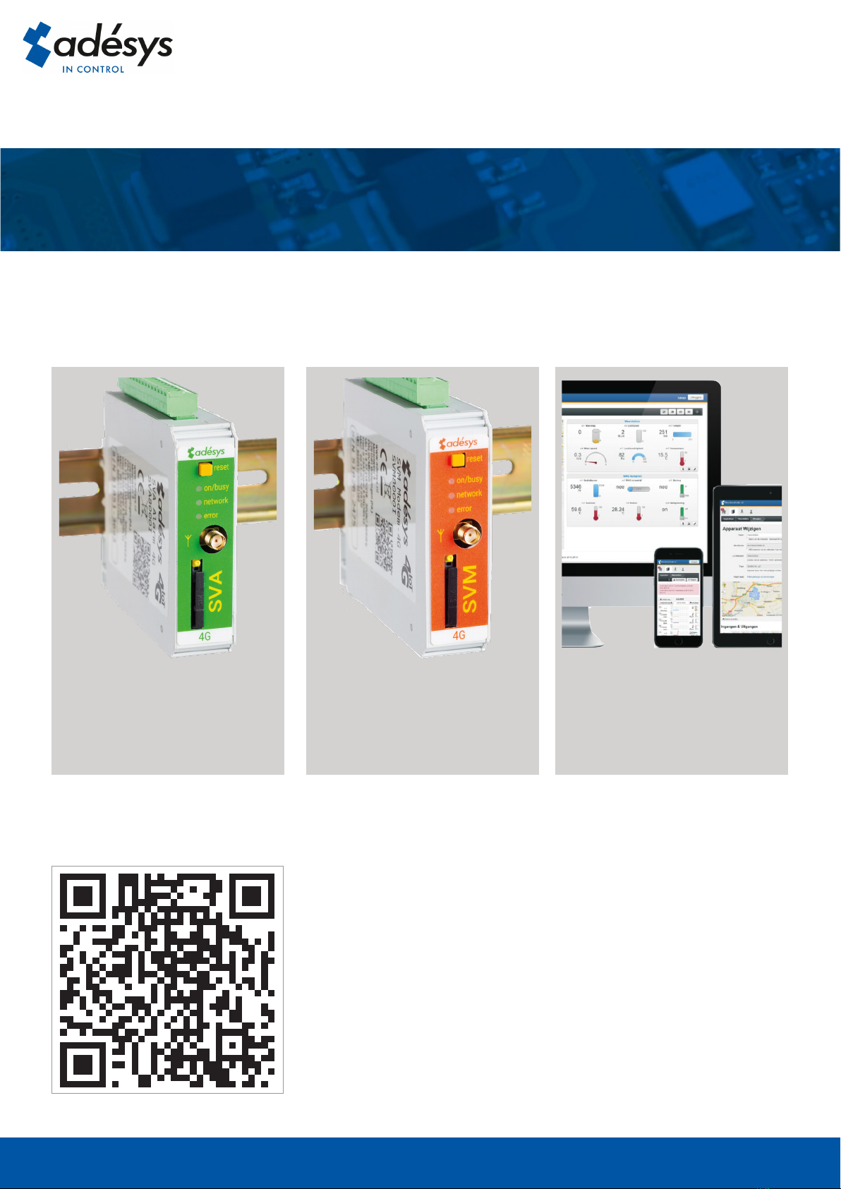
Also available in this SV-product line:
SVA 4G alarm dialler SVM 4G modem Checkmyprocess.com
Industrial 4G SMS/E-mail
alarm dialler for monitoring of
your technical processes.
Industrial 4G modem/sms
alarm dialler for connection to
applicationsintheeld.
Convenient display of current
measured values from
your process.
Version 06-2019
This manual suits for next models
6
Table of contents
Other Adesys Control Unit manuals

Popular Control Unit manuals by other brands


Gecko
Gecko in.yt-7 0611-221031-361 Quick start card

Kramer
Kramer TBUS-5i installation instructions

TriMark
TriMark e-ASK Consumers manual

ATEQ
ATEQ G6 Series manual

The Human Solution
The Human Solution Uplift 80 manual

Bardiani Valvole
Bardiani Valvole MIXPROOF B915PMO Instruction, use and maintenance manual