manuals.online logo
Brands
  1. Home
  2. •
  3. Brands
  4. •
  5. Gecko
  6. •
  7. Control Unit
  8. •
  9. Gecko in.yt-7 0611-221031-361 Technical manual

Gecko in.yt-7 0611-221031-361 Technical manual

Other Gecko Control Unit manuals

Gecko TSPA-1 Reference guide

Gecko

Gecko TSPA-1 Reference guide

Gecko in.xe-5 0602-221063-299 Technical manual

Gecko

Gecko in.xe-5 0602-221063-299 Technical manual

Gecko IN.XE-5 0602-221046 Technical manual

Gecko

Gecko IN.XE-5 0602-221046 Technical manual

Gecko 1001 Reference guide

Gecko

Gecko 1001 Reference guide

Gecko SC-CF-SBD User manual

Gecko

Gecko SC-CF-SBD User manual

Gecko In.Touch 0608-521012 User manual

Gecko

Gecko In.Touch 0608-521012 User manual

Popular Control Unit manuals by other brands

Seitz 14A80 user manual

Seitz

Seitz 14A80 user manual

Wilo RS485 Installation and operating instructions

Wilo

Wilo RS485 Installation and operating instructions

Becker CentralControl CC41 Commissioning Instruction

Becker

Becker CentralControl CC41 Commissioning Instruction

SICK CDB650 operating instructions

SICK

SICK CDB650 operating instructions

Panduit NetKey NKP5E88M Series installation instructions

Panduit

Panduit NetKey NKP5E88M Series installation instructions

MX Options Concentric Petite Fitting instructions

MX

MX Options Concentric Petite Fitting instructions

Clean Water Systems Fleck 2510 Installation & start?up guide

Clean Water Systems

Clean Water Systems Fleck 2510 Installation & start?up guide

Fairchild FSB44104A user guide

Fairchild

Fairchild FSB44104A user guide

LEGRAND Wattstopper LMIN-104 installation instructions

LEGRAND

LEGRAND Wattstopper LMIN-104 installation instructions

PMK ATT10BNCS instruction manual

PMK

PMK ATT10BNCS instruction manual

Tektronix TDS3FFT user manual

Tektronix

Tektronix TDS3FFT user manual

Woodward easYgen Technical manual

Woodward

Woodward easYgen Technical manual

Balluff BNI EIP-502-105-R015 user guide

Balluff

Balluff BNI EIP-502-105-R015 user guide

NXP Semiconductors TWR-LS1021A Getting started

NXP Semiconductors

NXP Semiconductors TWR-LS1021A Getting started

Advantech PCM-3117 Startup manual

Advantech

Advantech PCM-3117 Startup manual

Danfoss MCO 101 manual

Danfoss

Danfoss MCO 101 manual

Moons' Lin Engineering R701P user manual

Moons'

Moons' Lin Engineering R701P user manual

Aventics RV1 operating instructions

Aventics

Aventics RV1 operating instructions

manuals.online logo
manuals.online logoBrands
  • About & Mission
  • Contact us
  • Privacy Policy
  • Terms and Conditions

Copyright 2025 Manuals.Online. All Rights Reserved.

1- Connect all outputs & keypads
3- Select spa configuration (if prompt on startup)
3
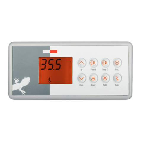
At first startup the keypad display
will show Lx or LLx, where « x »
representing the config. number. Some
spa packs come with a pre-selected
config. and you may skip this step if
your system automatically starts up1.
Use the Up/Down key to choose the
new low level configuration number.
Press the Program2key to confirm
the selection.
21
2- Connect the main power
Light outputs
(P34 always on, P35 relay controlled)
Main power
entry connection
Heater
connections
Heater
Bonding lugs
A1
A2
A3
A4
C3
C2
C1
H L GC
A4
A3
A2
A1
C1 - Main keypad connector
CO - Communication links (2 ports)
in.touch, in.stik, Aux keypad in.k112,
Swim Spa com. cable, etc.
For 240 V (4 wires)
Connect wiring of the electrical
service box GFCI. Neutral wire is
mandatory.
For 120 V (*3 wires)
* If connected to a 3 wire system,
any 240 V components will not
work.
For 240 V (4 wires)
L2
N
L1
G
For 120 V (*3 wires)
WARNING! All connections must be made by a qualified electrician in accordance with the national electrical code and any state, provincial or local electrical code in
effect at the time of the installation. This product must always be connected to circuit protected by a Ground Fault Circuit Interrupter (GFCI).
2.a- Electrical wiring
Heater voltage
Verify BROWN common wire
connection to tab:
P9 - 240 V (default)
P10 - 120 V
Pumps & accessories voltage
Verify each WHITE common wire
connection to tab:
N - 120 V (default)
L2 - 240 V pump/acc.
P9
2.b- Heater & pump/accessories voltage
P10
N
L1
G
G C HL
C1
C2
C3
AMP ports (A0 to A4,
and C1 to C3) for pumps
& accessories. Function
varies per configuration
(see next page).
A0
H L GC Optional
floating connector
(Part #9920-401346)
1 Note: To re-enter the low level
selection menu, hold the Pump 1
key for 30 seconds.
Note: For the Color keypad series,
select Settings menu, go into
Electrical config and choose the
appropriate Low level.
2Note: If the keypad does not have
a Program or Filter key, use the
Light key instead.
For more information, see our
website: www.geckoalliance.com
4- Select breaker current

GFCI b
60 A 48 A
50 A 40 A
40 A 32 A
30 A 24 A
20 A 16 A
15 A 12 A
321
(10 to 20 A dedicated to 120 V)
Press and hold the Program key
for 20 seconds until you access the
breaker setting menu.
Note: For the Color keypad series,
select Settings menu, go into Electri-
cal config and choose Input current.
Use the Up/Down key to select the
desired value. Then press the Program
key to confirm the selection.
Note: If the keypad does not have the
Program or Filter key, use the Light
key instead.
The values displayed by the system
correspond to 80% of the maximum
amperage capacity of the GFCI.
For more information, see our
website: www.geckoalliance.com
Quick Start Card
in.yt-7™North American version
Standard
config. # Pump 1 Pump 2 Pump 3 Pump 4 Pump 5 Blower Light 2 DIRECT 2 Circ. Pump (CP)
configuration
Ozone (O3)
configuration1
Filter cycle
daily Heater pump
1
1SP
(A3)
12A
1SP
(A2)
10A
1SP
(C3)
10A
_ _ _ _ DIR
During filter cycle
(C2)
1A
During filter cycle with CP
(A1)
0A
2 * 6 hours
(with CP)
With CP
8A (2KW)
2
1SP
(A3)
12A
1SP
(A2)
10A
1SP
(C3)
10A
_ _
X
(A4)
4A
_ DIR
During filter cycle
(C2)
1A
During filter cycle with CP
(A1)
0A
2 * 6 hours
(with CP)
With CP
8A (2KW)
3
1SP
(A3)
12A
1SP
(A2)
10A
1SP
(C3)
10A
1SP
(A4)
8A
_ _ _ DIR
During filter cycle
(C2)
1A
During filter cycle with CP
(A1)
0A
2 * 6 hours
(with CP)
With CP
8A (2KW)
4
1SP
(A3)
12A
1SP
(A2)
10A
1SP
(C3)
10A
1SP
(A4)
8A
_
X
(A1)
4A
_ DIR
During filter cycle
(C2)
1A
During filter cycle with CP
(K2-P Tab)
0A
2 * 6 hours
(with CP)
With CP
8A (2KW)
5
1SP
(A3)
12A
1SP
(A2)
10A
1SP
(C3)
10A
1SP
(A4)
8A
1SP
(A1)
8A
_ _ DIR
During filter cycle
(C2)
1A
During filter cycle with CP
(K2-P Tab)
0A
2 * 6 hours
(with CP)
With CP
8A (2KW)
6
1SP
(A3)
12A
1SP
(A2)
10A
1SP
(C3)
10A
1SP
(A4)
8A
1SP
(A1)
8A
X
(K2-P Tab)
4A
_ DIR
During filter cycle
(C2)
1A
_
2 * 6 hours
(with CP)
With CP
8A (2KW)
7
2SP
(A3)
12A-3A
1SP
(A2)
10A
1SP
(C3)
10A
_ _ _ _ DIR _
During filter cycle with P1
(A1)
0A
2 * 2 hours
with P1
With P1
8A (2kW)
8
2SP
(A3)
12A-3A
1SP
(A2)
10A
1SP
(C3)
10A
_ _
X
(A4)
4A
_ DIR _
During filter cycle with P1
(A1)
0A
2 * 2 hours
with P1
With P1
8A (2kW)
9
2SP
(A3)
12A-3A
1SP
(A2)
10A
1SP
(C3)
10A
_ _ _ _ DIR
During filter cycle
(C2)
1A
During filter cycle with CP
(A1)
0A
2 * 6 hours
(with CP)
With CP
8A (2KW)
10
2SP
(A3)
12A-3A
1SP
(A2)
10A
1SP
(C3)
10A
_ _
X
(A4)
4A
_ DIR
During filter cycle
(C2)
1A
During filter cycle with CP
(A1)
0A
2 * 6 hours
(with CP)
With CP
8A (2KW)
11
2SP
(A3)
12A-3A
1SP
(A2)
10A
1SP
(C3)
10A
1SP
(A4)
8A
_ _ _ DIR _
During filter cycle with P1
(A1)
0A
2 * 2 hours
with P1
With P1
8A (2kW)
12
2SP
(A3)
12A-3A
1SP
(A2)
10A
1SP
(C3)
10A
1SP
(A4)
8A
_
X
(C2)
4A
_ DIR _
During filter cycle with P1
(A1)
0A
2 * 2 hours
with P1
With P1
8A (2kW)
13
2SP
(A3)
12A-3A
1SP
(A2)
10A
1SP
(C3)
10A
1SP
(A4)
8A
_ _ _ DIR
During filter cycle
(C2)
1A
During filter cycle with CP
(A1)
0A
2 * 6 hours
(with CP)
With CP
8A (2KW)
14
2SP
(A3)
12A-3A
1SP
(A2)
10A
1SP
(C3)
10A
1SP
(A4)
8A
_
X
(A1)
4A
_ DIR
During filter cycle
(C2)
1A
_
2 * 6 hours
(with CP)
With CP
8A (2KW)
15
2SP
(A3)
12A-3A
1SP
(A2)
10A
1SP
(C3)
10A
1SP
(A4)
8A
1SP
(A1)
8A
_ _ DIR _
During filter cycle with P1
(C2)
0A
2 * 2 hours
with P1
With P1
8A (2kW)
16
2SP
(A3)
12A-3A
1SP
(A2)
10A
1SP
(C3)
10A
1SP
(A4)
8A
1SP
(A1)
8A
X
(C2)
4A
_ DIR _ _
2 * 2 hours
with P1
With P1
8A (2kW)
17
2SP
(A3)
12A-3A
1SP
(A2)
10A
1SP
(C3)
10A
1SP
(A4)
8A
1SP
(A1)
8A
_ _ DIR
During filter cycle
(C2)
1A
_
2 * 6 hours
(with CP)
With CP
8A (2KW)
18
2SP
(A3)
12A-3A
2SP
(A2)
10A-3A
1SP
(C3)
10A
_ _ _ _ DIR _
During filter cycle with P1
(A1)
0A
2 * 2 hours
with P1
With P1
8A (2kW)
19
2SP
(A3)
12A-3A
2SP
(A2)
10A-3A
1SP
(C3)
10A
_ _
X
(C2)
4A
_ DIR _
During filter cycle with P1
(A1)
0A
2 * 2 hours
with P1
With P1
8A (2kW)
20
2SP
(A3)
12A-3A
2SP
(A2)
10A-3A
1SP
(C3)
10A
_ _ _ _ DIR
During filter cycle
(C2)
1A
During filter cycle with CP
(A1)
0A
2 * 6 hours
(with CP)
With CP
8A (2KW)
21
2SP
(A3)
12A-3A
2SP
(A2)
10A-3A
1SP
(C3)
10A
_ _
X
(A1)
4A
_ DIR
During filter cycle
(C2)
1A
_
2 * 6 hours
(with CP)
With CP
8A (2KW)
22
2SP
(A3)
12A-3A
2SP
(A2)
10A-3A
2SP
(C3)
10A-3A
_ _ _ _ DIR _
During filter cycle with P1
(A1)
0A
2 * 2 hours
with P1
With P1
8A (2kW)
23
2SP
(A3)
12A-3A
2SP
(A2)
10A-3A
2SP
(C3)
10A-3A
_ _
X
(A1)
4A
_ DIR _ _
2 * 2 hours
with P1
With P1
8A (2kW)
24
2SP
(A3)
12A-3A
2SP
(A2)
10A-3A
2SP
(C3)
10A-3A
_ _ _ _ DIR
During filter cycle
(A1)
1A
_
2 * 6 hours
(with CP)
With CP
8A (2kW)
25
2SP
(A3)
12A-3A
1SP
(A2)
10A
_ _ _ _
X
(A4) DIR _
During filter cycle with P1
(A1)
0A
2 * 2 hours
with P1
With P1
8A (2kW)
26
2SP
(A3)
12A-3A
1SP
(A2)
10A
_ _ _
X
(C3)
4A
X
(A4) DIR _
During filter cycle with P1
(A1)
0A
2 * 2 hours
with P1
With P1
8A (2kW)
27
2SP
(A3)
12A-3A
1SP
(A2)
10A
_ _ _ _
X
(A4) DIR
During filter cycle
(C2)
1A
During filter cycle with CP
(A1)
0A
2 * 6 hours
(with CP)
With CP
8A (2kW)
28
2SP
(A3)
12A-3A
1SP
(A2)
10A
_ _ _
X
(C3)
4A
X
(A4) DIR
During filter cycle
(C2)
1A
During filter cycle with CP
(A1)
0A
2 * 6 hours
(with CP)
With CP
8A (2kW)
29
2SP
(A3)
12A-3A
2SP
(A2)
10A-3A
_ _ _ _
X
(C2) DIR _
During filter cycle with P1
(A1)
0A
2 * 2 hours
with P1
With P1
8A (2kW)
30
2SP
(A3)
12A-3A
2SP
(A2)
10A-3A
_ _ _
X
(C3)
4A
X
(C2) DIR _
During filter cycle with P1
(A1)
0A
2 * 2 hours
with P1
With P1
8A (2kW)
Configuration selection chart
Software #361, rev. 001
For complete TechBook or more information, see our website: www.geckoalliance.com
9919-101500-A Rev. 07-2016 www.geckoalliance.com
© Groupe Gecko Alliance Inc., 2016
All trademarks or registered trademarks are the property of their respective owners.
1When the Ozonator is not controlled by a relay, it can be tied to Pump 1 Low speed or Circ. Pump. Pump using cable splitter AMP PN: 9920-401369.
Glossary
P1 Pump 1
CP Circulation Pump
XInstalled
1SP High speed only
2SP High and Low speed
(OUT, AMP, Relay, Tab) Output connector
12A, 12A-3A Output current: 1 speed or High - Low speed