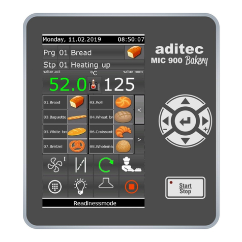
aditec MIC 900 User manual

User Manual
MIC 900 / MIC 1100 / MIC 3000
Process controller
V00.21
Issue 17.08.2021_00
Measurement and
Control technology
Hardware development
Software development
Specialised electronics
Food technology
Process visualisation
aditec gmbh
Talweg 17
D-74254 Offenau
Tel.:+49(0)7136 96122-0
Fax:+49(0)7136 96122-20
www.aditec.net
eMail: info@aditec.net

User Manual MIC 900 / MIC 1100 / MIC 3000
2
Issue 17.08.2021_00
Contents
1Introduction .....................................................................................................................................5
1.1 Overview ....................................................................................................................................5
1.2 Display and operating area........................................................................................................6
1.2.1 Input and display touch panel.............................................................................................6
1.2.2 Control buttons....................................................................................................................6
1.3 Functions of the on-screen key pad...........................................................................................9
1.3.1 MIC 1100 / MIC 3000 Operating buttons (number and letter buttons)...............................9
1.4 Entering numerical values........................................................................................................10
1.4.1 MIC3000 Control buttons (number buttons) .....................................................................11
1.4.2 Screen lock.......................................................................................................................11
2Standby ..........................................................................................................................................12
2.1 Program groups and program images in standby....................................................................12
2.2 Selecting a program.................................................................................................................13
2.2.1 Program number:..............................................................................................................13
2.2.2 Program name..................................................................................................................13
2.2.3 Favourites list....................................................................................................................13
2.3 Selecting a step........................................................................................................................13
2.3.1 Selection via the process name........................................................................................14
2.3.2 Selection via the step number ..........................................................................................14
2.3.3 Using the task bar to switch into the next step .................................................................14
2.4 Actual and nominal values.......................................................................................................15
2.5 Program run times....................................................................................................................16
2.6 Optional displays......................................................................................................................16
2.6.1 Optional nominal values ...................................................................................................16
2.6.2 Process display.................................................................................................................17
2.6.3 Aggregate and relay display.............................................................................................17
2.6.4 Messages (system status messages) ..............................................................................17
2.6.5 Alarm messages...............................................................................................................18
2.6.6 Optional control loops / measured values ........................................................................18
2.6.7 Favourites.........................................................................................................................18
2.6.8 Aggregate buttons ............................................................................................................18
2.6.9 Aggregate modules...........................................................................................................18
2.6.10 Switching into the next step..............................................................................................19
2.6.11 Analogue outputs..............................................................................................................19
2.7 Task bar ...................................................................................................................................19
2.7.1 Start page / profiles:..........................................................................................................19
2.7.2 Programs: .........................................................................................................................19
2.7.3 Editing a program step:.....................................................................................................20
2.8 Information bar.........................................................................................................................20
3Menu page......................................................................................................................................20
4Programming mode ......................................................................................................................21
4.1 Selecting a program.................................................................................................................21
4.2Setting up a favourites list........................................................................................................22
4.3 Editing program steps..............................................................................................................22
4.3.1 Display for editing program steps.....................................................................................22
4.3.2 Assign program images....................................................................................................23
4.3.3 Entering nominal values ...................................................................................................24
4.3.4 Entering a Delta value ......................................................................................................24
4.3.5 Setting up repetitive steps ................................................................................................24
4.3.6 Copying, deleting and adding programs/steps .................................................................25
4.4 Linking programs......................................................................................................................26
4.5 Create/change cleaning times in programming mode .............................................................27
4.6 Setting up a program with VisuNet ..........................................................................................27
4.6.1 Enabling VisuNet ..............................................................................................................28
4.6.2 Editing programs with VisuNet..........................................................................................28
5Program start.................................................................................................................................28

User Manual MIC 900 / MIC 1100 / MIC 3000
3
Issue 17.08.2021_00
5.1.1 Instant start.......................................................................................................................28
5.1.2 Start with time of day ........................................................................................................28
5.1.3 Starting a program with batch number .............................................................................29
5.1.4 Sensor log on or off (Sensor registration).........................................................................29
5.1.5 Operating hours messages on the user pages.................................................................30
6Operating mode.............................................................................................................................31
6.1 Shut-down conditions...............................................................................................................32
6.1.1 Negative core shut-down (Showering/cooling).................................................................32
6.1.2 FC value............................................................................................................................32
6.2 Transient changes to the nominal values ................................................................................33
6.3 Batch number during operation................................................................................................33
6.4 Switching into the next step or previous step ..........................................................................34
6.5 Pausing a program...................................................................................................................34
6.6 Single step control....................................................................................................................34
6.7 Alarm signal .............................................................................................................................34
6.8 Maximum step time display......................................................................................................35
6.9 Checking cleaning times in the operating mode......................................................................35
6.10 Fast dehumidifying ...............................................................................................................36
7Information page ...........................................................................................................................36
8Profiles ...........................................................................................................................................36
8.1 Date and time...........................................................................................................................37
8.2 Enabling data logger................................................................................................................37
8.3Enabling and disabling a signal ...............................................................................................39
8.4 Enabling batch number............................................................................................................39
8.5 Loading programs....................................................................................................................40
8.5.1 Loading progams..............................................................................................................40
8.5.2 Copying programs onto a USB.........................................................................................41
8.5.3 Saving data logger data onto a USB ................................................................................41
8.6 Show versions..........................................................................................................................41
8.7 Administrators (from V00.07)...................................................................................................42
8.7.1 Configuration/changes to the administrator settings ........................................................42
8.7.2 Display of the current user in operating mode..................................................................44
8.8 Operating hour counter reading...............................................................................................45
8.9 Screensaver.............................................................................................................................45
9Power failure..................................................................................................................................46
10 List of errors (possible problems) ...........................................................................................47
11 Connection diagram..................................................................................................................48
11.1 MIC 900................................................................................................................................48
11.2 MIC 1100..............................................................................................................................49
11.3 MIC 3000..............................................................................................................................50
12 Technical data............................................................................................................................50
12.1 MIC 900................................................................................................................................50
12.2 MIC 1100..............................................................................................................................50
12.3 MIC 3000..............................................................................................................................51
13 Index ...........................................................................................................................................51
14 Safety instructions ....................................................................................................................52

User Manual MIC 900 / MIC 1100 / MIC 3000
4
Issue 17.08.2021_00
Symbols used in this user manual
The following symbols are used in this user manual to emphasize important information:
Symbol
Description
This is a Please note or a tip.
Be aware!
This symbol points out potential problems and what to do to avoid them.
Shows a sequence of actions that should be executed one after the other.

User Manual MIC 900 / MIC 1100 / MIC 3000
5
Issue 17.08.2021_00
1 Introduction
1.1 Overview
Processors MIC 900, MIC 1100 and MIC 3000,
with user-friendly touch panel, 7“ TFT display with resistive touch technology, several interfaces and a
housing of standard industrial quality, are designed for use in universal cooking and smoking
chambers as well as climatic smoke and maturing chambers.
In its standard version the controller is equipped with
4 Pt100 temperature inputs and
2 inputs which can be converted to Pt100 and current 4-20mA / voltage 0-10V or thermocouples
(compliant with DIN EN 60584).
The following interfaces allow communication: LAN/Ethernet and USB Serial Port.
In order to adapt the controller for specific purposes each control loop can be used as a 2-point
controller, XP controller or with PID behaviour.
MIC 900:
The standard version has 16 relay outputs
(12 normally open contacts and 4 changeover contacts).
MIC 1100:
In its standard version the controller is equipped with 18 relay outputs
(14 normally open contacts and 4 changeover contacts).
MIC 3000:
The standard version has 24 relay outputs
(16 normally open contacts and 8 changeover contacts).

User Manual MIC 900 / MIC 1100 / MIC 3000
6
Issue 17.08.2021_00
1.2 Display and operating area
The controller is sub-divided into an input/display panel and a control button panel.
1.2.1 Input and display touch panel
The upper half is a 5" (MIC 1100) or 7“ (MIC 900 + MIC 3000) touch display. Here you can change the
different settings and information on program data and the input screens are shown.
1.2.2 Control buttons
The control buttons allow you to navigate through the operating elements of the touch display with the
help of the cursor buttons. Use the “Enter”button to confirm the entries you have made.
Controllers MIC 1100 and MIC 3000 had short-cut buttons that allow you to select operating elements
directly.
Some control buttons have LEDs. The LEDs give a visual indication of various aggregate conditions.
MIC 900
MIC 1100
MIC 3000

User Manual MIC 900 / MIC 1100 / MIC 3000
7
Issue 17.08.2021_00
MIC 900, MIC 1100 and MIC 3000
Only
MIC 900 +
MIC 3000
Pause
Pausing program runs and resuming a paused program
run.
LED flashes –program in hold mode/start time runs
Start / Stop
Starting and stopping programs.
LED lights –control in operation
LED flashes –end of the program
Cursor left -
Moving horizontally to the next operating element on the
left.
Cursor right +
Moving horizontally to the next operating element on the
right.
Cursor up
Moving vertically up to the next operating element.
Entering number values (incremented).
Cursor down
Moving vertically down to the next operating element.
Entering number values (decremented).
Cursor ENTER
Confirm the selected button/box
Only MIC 1100 + MIC 3000
Control buttons 1-5
Depending on the page that is currently displayed, the
functions of the buttons change. The current
function/description of the button corresponds to the
buttons on the task bar.
On the menu display you can see the following
descriptions:
F1 –Configuration
F2 –Service
F3 –Start page
F4 –Profiles
F5 –Programs
Chamber
temperature
Short-cut button for entering nominal chamber
temperature value (min, max)
LED shines –heating is active
Step time
Short-cut button for entering the nominal step time
LED shines –control in operation
Repetition
The function button can be allocated freely (in
preparation)
(only MIC 3000)
Humidity max
Short-cut button for entering the nominal humidity value
max
LED shines –dehumidification is active
Core temperature
Short-cut button for entering the nominal core
temperature value
LED shines –cooling is active

User Manual MIC 900 / MIC 1100 / MIC 3000
8
Issue 17.08.2021_00
Air circulation level
Short-cut button for changing the circulation level on a
multi-level motor (if it has been configured that way)
LED shines –air circulation level 1 is active (low)
LED flashes slowly –air circulation level 2 is active
(intermediate)
LED flashes quickly –air circulation level 3 is active
(high)
(only MIC 3000)
Delta
Short-cut button for entering the Delta value
Humidity min
Short-cut button entering the nominal humidity value, min
LED shines –humidification is active
MIC 3000
MIC 1100
Program number
Program number entry
Step
Switching into the next step, selecting a step
Line
Confirming an entry and highlighting the next object.
Test mode
(only MIC 3000)
Calling up test mode / Changing the key board mode
(numbers / capital letters/ lower case letters)
LED off –number
LED shines –lower case letters
LED flashes –capital letters
...
Numerical pad
Number or signs entry
(only MIC 3000)
Plus/Minus
Switching from positive to negative values
(only MIC 3000)
Manual program
Button is without function at the moment
Please note
Short-cut buttons allow you to access specific nominal values directly (and actual values during
operation) in order to check or change values.

User Manual MIC 900 / MIC 1100 / MIC 3000
9
Issue 17.08.2021_00
1.3 Functions of the on-screen key pad
Key pad
- Insert/replace mode
- Deleting individual symbols
- Deleting an entire text passage
- Capital /Lower case letters
- Numbers and special symbols
- Confirm entry
- Leaving the operation without changing the
original settings
- More special symbols
1.3.1 MIC 1100 / MIC 3000 Operating buttons (number and letter buttons)
Numerical pad text entry MIC 1100

User Manual MIC 900 / MIC 1100 / MIC 3000
10
Issue 17.08.2021_00
Numerical pad text entry MIC 3000
Text can also be entered via the operation buttons 0 –9. Select which value you want to enter via the
cursor buttons and then change into entry mode by pressing the Return button. Now use the operation
buttons on the numerical pad to enter your value and confirm your entry by pressing Return. The
cursor can be moved via the arrow buttons.
Be aware
You can skip between keypad modes by pressing the „Test“ button. While you are
entering text, the LED in the „Test“ button will show the selected keypad mode.
LED off –number
LED lit –lower case letters
LED flashing –capital letters
If you want to delete a symbol, take the cursor to the position you want to delete and overwrite it with
a blank space. Press button „9“ 3 times or button „0“ once and a blank space will appear.
Entering special symbols
Special symbols can be entered via the „0“ button. The following symbols are available:
leer
.
,
!
?
%
/
_
-
+
=
#
*
(
)
1.4 Entering numerical values
A numerical pad is used to enter numerical values. It will be displayed when
you have to enter values.
- Deleting the value in an entry box
- Changing the leading sign of a value
- Closing the keypad. Changes made to the nominal value
are not saved.
- De-activating a nominal value
- Saving an entered value
Numerical pad

User Manual MIC 900 / MIC 1100 / MIC 3000
11
Issue 17.08.2021_00
Be aware
The controller also allows you to enter negative temperature values:
-In order to pre-program negative nominal values in a step, the installation manufacturer
has to pre-program negative nominal value limits for chamber and core.
- „0“ can be entered as a nominal value. The nominal value „Off“ is shown for chamber
and core when a new program step is pre-programmed. . This means: the nominal value
is deactivated. As soon as a value is entered (even if it is „0“) the nominal value counts
as activated. If you want to deactivate the nominal value later in the step, press
the „Off“ button.
1.4.1 MIC3000 Control buttons (number buttons)
Number pad MIC 1100
Number pad MIC 3000
Text can also be entered via the operation buttons 0 –9. Select which value you want to enter via the
cursor buttons and then change into entry mode by pressing the Return button. Now use the operation
buttons on the numerical pad to enter your value and confirm your entry by pressing Return.
1.4.2 Screen lock
When you press the „Enter“ button for 3 seconds, all buttons and touch function on the display will be
locked. On the bottom edge of the display you will see the lock symbol.
In order to de-activate the lock, press the „Enter“ button for about 5 seconds.
For your information
A program run is not affected by a button/keypad lock. This means that the program will
continue as normal, even if the keypad lock is activated while a program is in operation.
Neither the communication with VisuNet nor the service program are affected when a keypad
lock is activated. Programs can be started and stopped via VisuNet even if the keypad is
locked.
The function is mainly needed while the installation and the controller are being cleaned.

User Manual MIC 900 / MIC 1100 / MIC 3000
12
Issue 17.08.2021_00
2 Standby
As soon as the controller has been connected to a power supply, it will automatically boot up and will
display the message „Loading please wait...“. This process can take up to 1 minute. Then you will get
to the standby screen.
Be aware
Please do not operate the touch screen with sharp implements i.e. pointed fingernails,
pens/pencils, screwdrivers etc. Only use blunt, soft implements i.e. fingers, rubber pens.
Current Program bar
Pr.group Step bar
Current Optional
Pr.image displays
(menu of favourites)
Actual value display
Symbols | Scale
Select program group
Status bar
System time
Task bar
In standby none of the programs has been selected, this means that nominal values are not displayed.
The current operating status of the installation is shown on the information bar.
2.1 Program groups and program images in standby
Hint
Program images/program groups are only displayed when the option is enabled. Ask your
service technician.
•Current program image: The current program is displayed (display only).

User Manual MIC 900 / MIC 1100 / MIC 3000
13
Issue 17.08.2021_00
•Current program proup:
The current program group (related to the current program) is
displayed. By touching the field, all programs belonging to this
program group are displayed and can be selected.
•Program group selection:
All 12 program groups are displayed. By touching the program
group, all programs belonging to this group are displayed and can
be selected.
Hint
Display of all programs which are not assigned to a program group:
Select program 00 →Touch the field current program group →all programs are displayed
which are not assigned to a program group
2.2 Selecting a program
Starting from standby mode, you have 3 options of how to select a program:
2.2.1 Program number:
Use the numerical pad to enter the program number
and confirm with „Enter“.
2.2.2 Program name
A menu list of all available programs will open. Select
the program you want and confirm with „Enter“.
2.2.3 Favourites list
Press on the program you want on the favourites list.
You can find information on how to set up a favourites list,
item 4.2
Setting up a favourites list, page 22.
2.3 Selecting a step
In standby you can select steps. This allows you to skip steps during operation or to repeat a step that
has already run. You can also select a step while in standby mode in order to e.g. check on the
entered nominal values or to start a program with the second or third step.
Starting from standby mode, there are 3 options of how to change steps:

User Manual MIC 900 / MIC 1100 / MIC 3000
14
Issue 17.08.2021_00
2.3.1 Selection via the process name
Selecting a process name
Press the box with the process name and a list of all the processes will open. From this list you can
now assign the required process to the step. Please press „Enter“ to confirm your choice.
2.3.2 Selection via the step number
Press the step number box and the on-screen numerical pad will open. Enter the required step
number via the pad and confirm with „Enter“.
Please note
In the step box you can also see current alarm messages (e.g. sensor fault).
2.3.3 Using the task bar to switch into the next step
Task bar
Use the arrow buttons to change into the previous or next step respectively.

User Manual MIC 900 / MIC 1100 / MIC 3000
15
Issue 17.08.2021_00
2.4 Actual and nominal values
Actual value:
Currently measured sensor value or current step time
Symbol/Scale (combined button):
Shows the measured variable and the measuring scale.
If the nominal value for chamber max. or humidity max. has
been enabled, the „Symbol“button allows you to change the
display from min. nominal value to max. nominal value. Which
nominal values is currently shown, can be seen in the nominal
value box (min./max.).
Nominal value:
Only the entry boxes for nominal values that have been enabled in the current process will be shown.
In standby nominal values are not shown, because neither a program nor a process has been
selected. Press the „nominal value“ box during operation and an entry box will open up to allow you to
change the nominal value. This is, however, a transient change that only applies while this step is
running and will not be saved.
Display of the actual step time during operation
(from version V00.08 onwards)
Colon in the actual time display is flashing –Step time is counted.
Colon in the actual time display is not flashing –Step time is not
counted.
Hint
When the step time counter has been paused, the step time is not counted. However, all
other control processes are taking place. All outputs (relays, analogue outputs, etc.) continue
to be actuated.
Normally the colon in the actual/current step time display will be flashing in operating mode.
When the step time counter has been paused, the colon is not flashing. The time is shown in
red.
Actual and nominal values
Act val.
Symbol
Scale
Nom.val
Chamber temp.
Core temp.
Humidity
Step time

User Manual MIC 900 / MIC 1100 / MIC 3000
16
Issue 17.08.2021_00
2.5 Program run times
Press the symbol to show the program runtime or the remaining program runtime.
Actual/current step time
Program runtime: Duration of the current program
(including all steps)
Remaining program runtime: Time that remains
until the program ends (including all steps). Only the
steps that have a pre-programmed step time are
taken into account.
Time paused
The time count is paused, the colon between the
minute and second (00:05) display is not flashing.
The display is shown in red.
Hint
The remaining program runtime is also calculated if steps without step time have been pre-
programmed. When a step without step time is in operation, the remaining program runtime
cannot be counted backwards. During these steps the colon in the remaining program
runtime display will not be flashing.
2.6 Optional displays
Depending on the configuration settings, different optional displays are available for the various
values. In some cases, settings can be changed via these displays.
Use the arrow button to browse through the enabled displays.
Browsing through
the optional displays
2.6.1 Optional nominal values
If additional nominal values (e.g. FC value, Delta temperature, air
circulation) or aggregate buttons have been enabled, they are all
shown on the „Optional nominal value“ list.
Press the current nominal value to change it during operation.
(Changeover ON/OFF or changing the values via the numerical
pad)
If the intelligent air circulation is programmed the active level
appears in green colour.
Be aware
The new nominal values are only valid in the current step. They are not saved and are
only valid until the end of the step. If you want to make permanent changes to the
nominal values you need to go to „Programming mode“, item 4, page 21 and make the
changes there.

User Manual MIC 900 / MIC 1100 / MIC 3000
17
Issue 17.08.2021_00
Please note
Aggregate modules, unlike aggregate buttons, can be programmed permanently and saved.
Also see „
Editing program steps“, item 4.3.1, page 22
The current status of the aggregates are shown under „Aggregate and relay display“, item
2.6.3, page 17
2.6.2 Process display
In the process display all the steps and the corresponding processes are
shown. The currently selected or currently running step is highlighted in
blue. This shows you clearly which processes have already run and
which are still to come.
2.6.3 Aggregate and relay display
All the aggregates which have been configured for the current process, together with their operating
status, are shown In this list
0 –Aggregate off
1 –Aggregate on
2.6.4 Messages (system status messages)
All digital inputs which have been configured as messages in a
process or program and their operating status are shown here.
0 –Contact open
1 –Contact closed
Please note
Messages are for information only and are not sent to
the recording program „VisuNet“.
Aggregate which have been
configured for the selected process
Aggregate buttons
Aggregate modules

User Manual MIC 900 / MIC 1100 / MIC 3000
18
Issue 17.08.2021_00
2.6.5 Alarm messages
All digital inputs which have been configured as alarms in a
process or program and their operating status are shown here.
0 –Contact open
1 –Contact closed
2.6.6 Optional control loops / measured values
The installation manufacturer can enable additional control loops
in every individual process. This list shows you the optional control
loops which have been enabled in the current process together
with their actual values.
2.6.7 Favourites
The programs that have been put on the favourites list are shown
in this display. Here you can select a program from the list.
How you can set up your own favourites list is described under„
Setting up a favourites list“ p.22.
2.6.8 Aggregate buttons
In this display a list of the aggregate buttons and their switching
status is shown. Certain relays can be switched on/off by the user
via these aggregate buttons.
2.6.9 Aggregate modules
In this display a list of the aggregate modules is shown. Certain
relays can be switched on/off by the user via these aggregate
buttons.

User Manual MIC 900 / MIC 1100 / MIC 3000
19
Issue 17.08.2021_00
There are 3 different types of buttons for aggregates and aggregate modules:
▪On/Off buttons
▪Buttons with interval time. The „On“time interval is fixed and is pre-configured by the installation
manufacturer. The „Off“time interval in seconds can be entered for each program by the end user.
▪Buttons with pulse interval. The base time is fixed and pre-configured by the installation
manufacturer. The end user can enter the length of the pulse interval in percent (in relation to the
base time) in each program.
2.6.10 Switching into the next step
If single step control has been enabled in the configuration, you
can set it to automatic (GO) or manual (STOP). Setting „GO“ will
disable single step control.
2.6.11 Analogue outputs
In this display the analogue outputs and their setting value are
listed. This display is only available if the configuration has been
set up accordingly.
2.7 Task bar
2.7.1 Start page / profiles:
The task bar is sub-divided into 5 task buttons. If you leave the start page/standby by pressing a
button, you can get back to standby by pressing the „Start page“ button on any page you may be on.
Menu: Press the „Menu“ button to get to the menu page
(see „Menu page“, item 3, page 20)
Arrow buttons(<, >): Press the arrow buttons right/left to skip forward or backwards from step to step
within a program.
Program: Press the „Program“ button to get to programming mode. For more information see:
item 4, page 21
Start: Starting a program. („Program start“, item 5, page 28)
2.7.2 Programs:
Start page: Calling up standby
Arrow buttons(<<, >>): Skipping through the program list in blocks of 10
Edit: Editing programs
Start: Starting programs. („Program start“, item 5, page 28)

User Manual MIC 900 / MIC 1100 / MIC 3000
20
Issue 17.08.2021_00
2.7.3 Editing a program step:
Back: Calling up the start page / standby
Arrow buttons(<, >): Press the arrow buttons right/left to skip forward or backwards from step to step
within a program.
Menü: Press the „Menu“ button to get to the menu page
(see „Menu page“, item 3, page 20)
Start: Starts programs. („Program start“, item 5, page 28)
2.8 Information bar
On the information bar you can see messages, operating status, alarm messages and the system
time.
3 Menu page
The „Menu“ page of the touch panel is arranged as follows:
Menu
▪Configuration:
System specific controller settings.
The settings are protected by a password and can only be set up by a service technician.
▪Service:
Settings for the maintenance personnel on-site: Initial start-up, maintenance work etc.
The settings are protected by a password and can only be set up by a service technician.
▪Profiles:
Settings for the operator/end user.
These settings are not password protected.
▪Programs:
Opens the program selection page.
This manual suits for next models
2
Table of contents
Other aditec Controllers manuals
Popular Controllers manuals by other brands
MegaTec
MegaTec NetAgent Mini user manual
Festo
Festo CMXR-C1 Programming instructions

Tascam
Tascam RC-W100-R120 user manual
PlanetCNC
PlanetCNC THC user manual

Mitsubishi Electric
Mitsubishi Electric Central Controller GB-50A Instruction book
Mitsubishi Electric
Mitsubishi Electric MELSEC Q Series user manual
