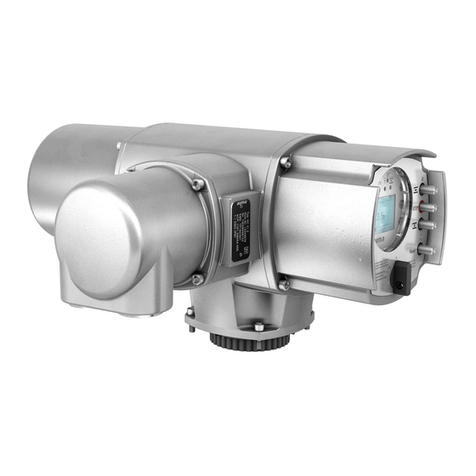
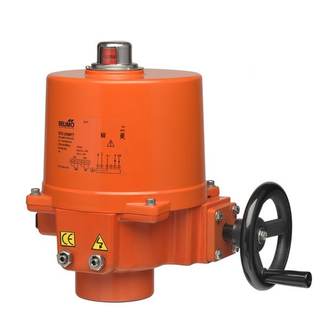
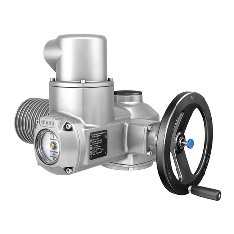
AUMA SG 05.1 User manual


Other manuals for SG 05.1
1
This manual suits for next models
3
Table of contents
Other AUMA Controllers manuals
AUMA
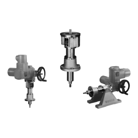
AUMA LE 12.1 User manual
AUMA
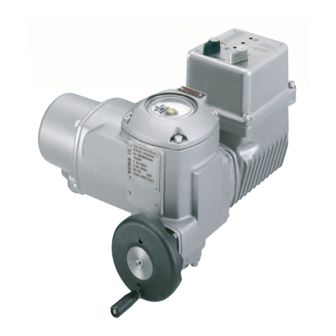
AUMA SG 03.3 Series User manual

AUMA
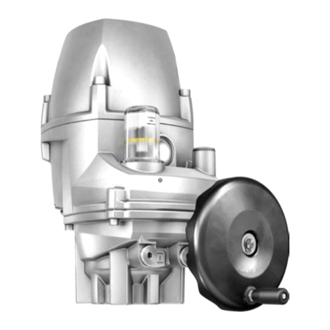
AUMA SAEx 25.1 User manual
AUMA
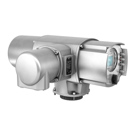
AUMA PROFOX PF-M25 User manual
AUMA
AUMA Aumatic AC 01.1 User manual
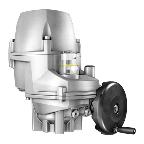
AUMA
AUMA PF-M25 Series Manual
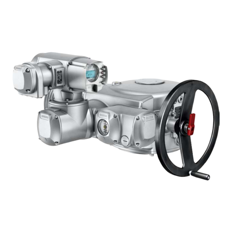
AUMA
AUMA SA 25.1 User manual
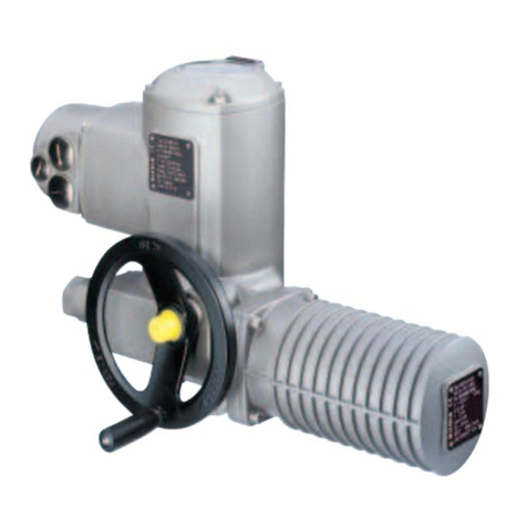
AUMA
AUMA SG 05.1-FA07 User manual
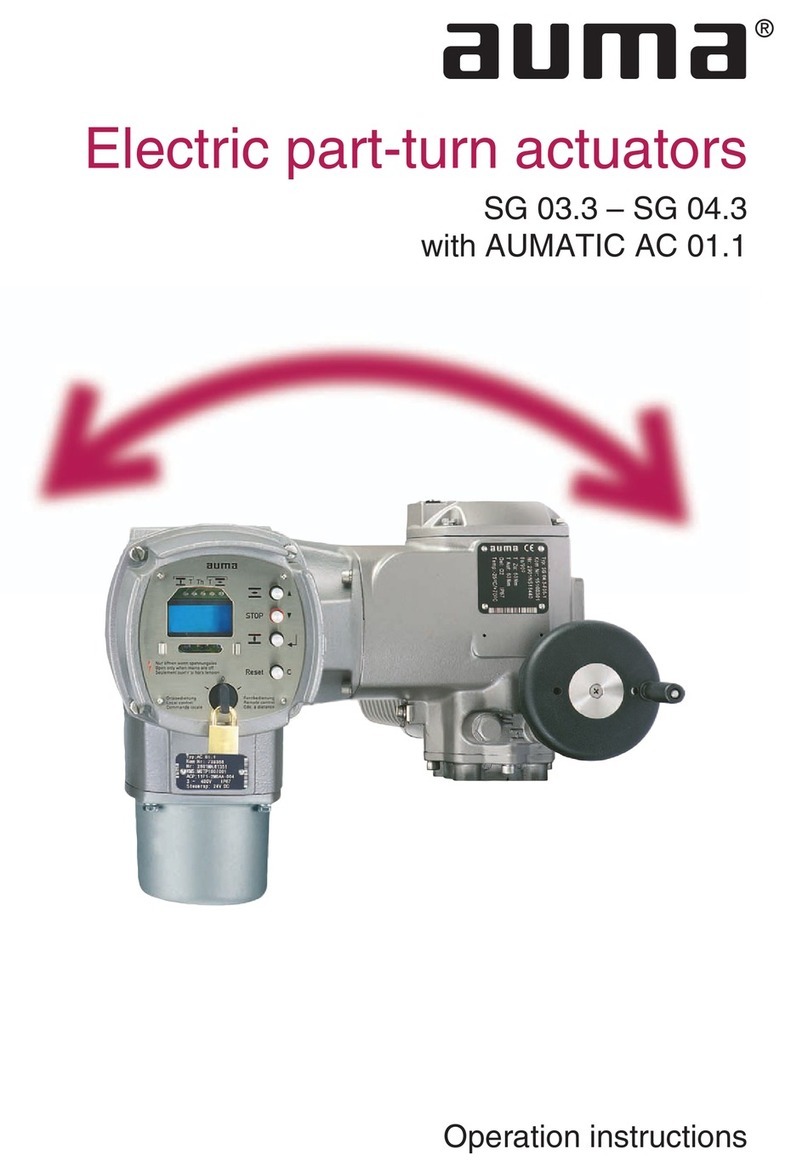
AUMA
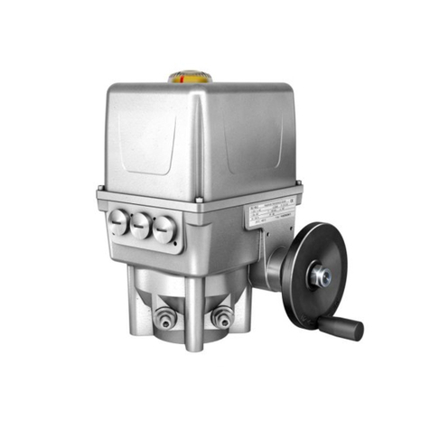
AUMA SG 03.3 Series User manual
AUMA
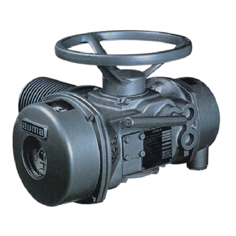
AUMA EQ 40 Assembly instructions
AUMA
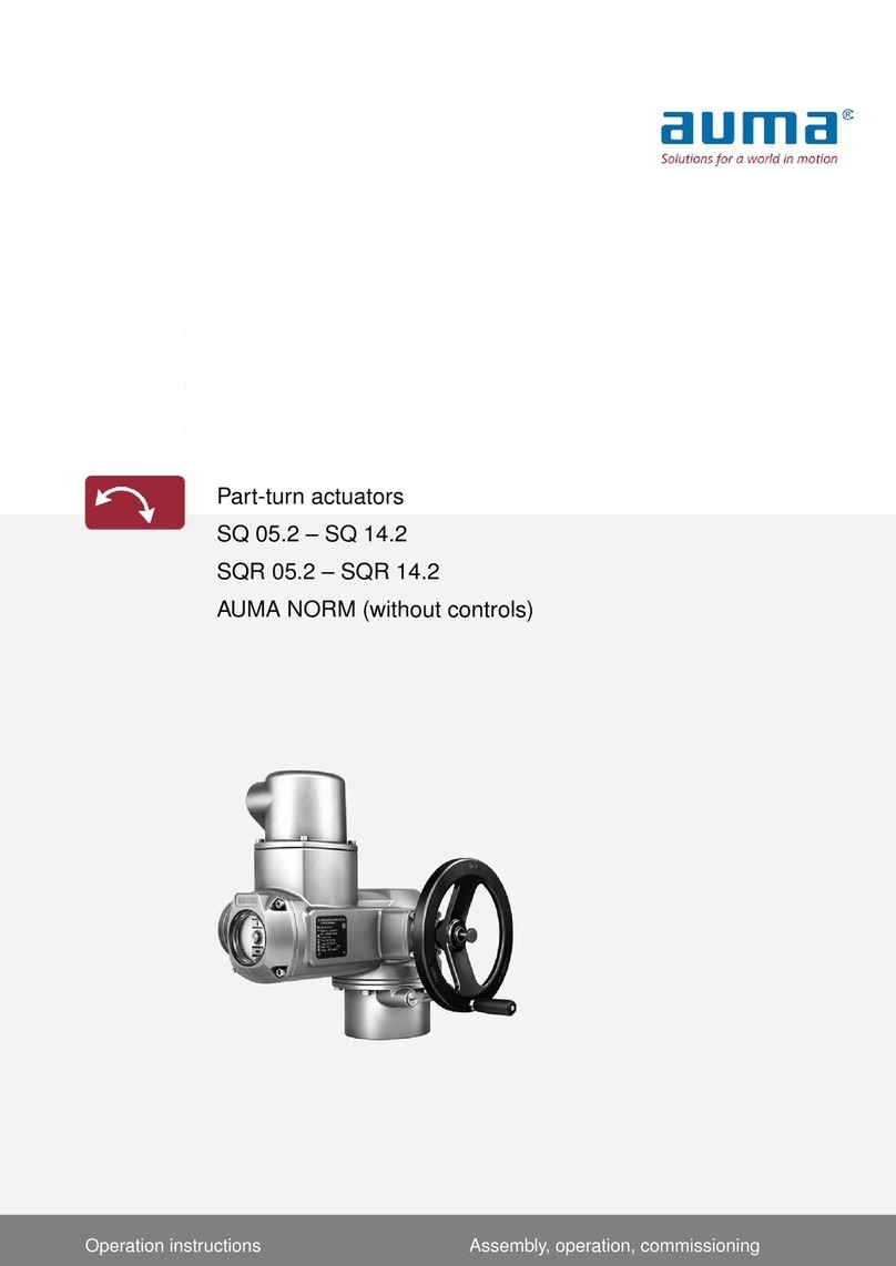
AUMA SA3-SA100 User manual
AUMA
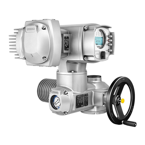
AUMA SQ 05.2 User manual
AUMA
AUMA SAVEx 07.2 User manual
AUMA
AUMA GST 10.1 Administrator Guide
AUMA
AUMA Profibus PBD 100 User manual
AUMA
AUMA SQEx 05.2 User manual
AUMA
AUMA SVCR 05.1 User manual
AUMA
AUMA SA 07.2 User manual
AUMA
AUMA SAExC 07.1 User manual

AUMA
AUMA SAN 07.1 User manual
Popular Controllers manuals by other brands
Nice HySecurity
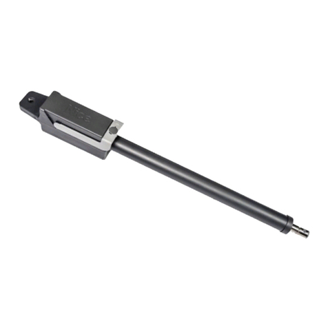
Nice HySecurity TITAN 912L Series Installation & reference manual
Universal Remote Control
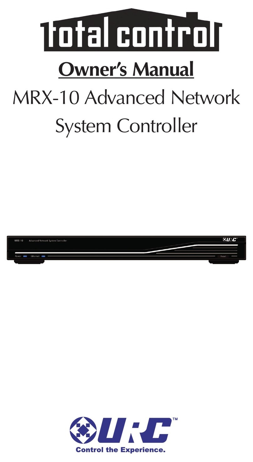
Universal Remote Control total control MRX-10 owner's manual
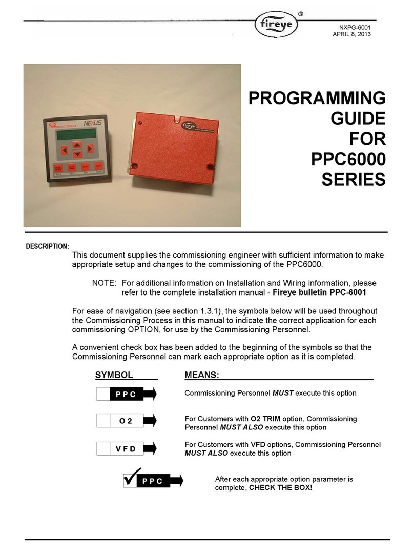
Fireye
Fireye PPC6000 Series Programming guide

Kapego LED
Kapego LED 843022 manual
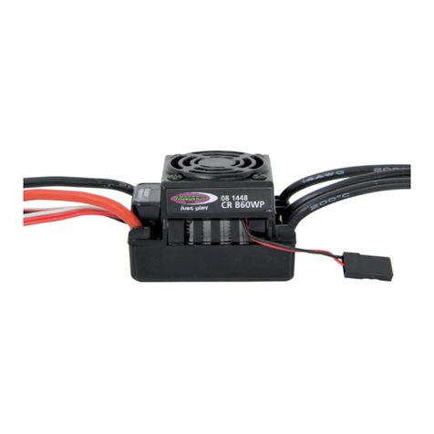
Jamara
Jamara Speed controller CRB60WP instructions
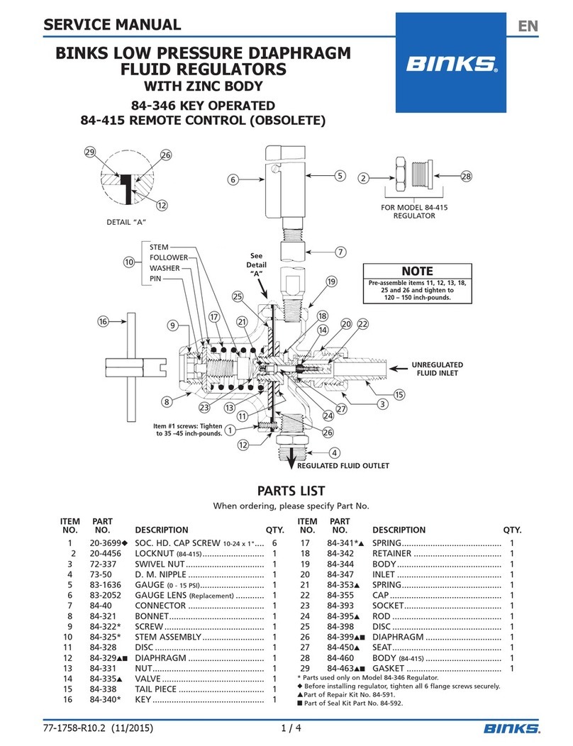
Binks
Binks 84-346 Service manual

