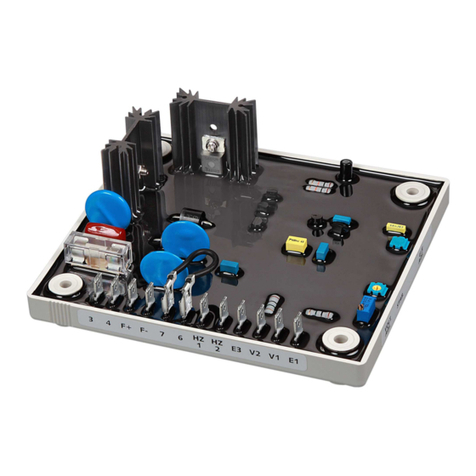
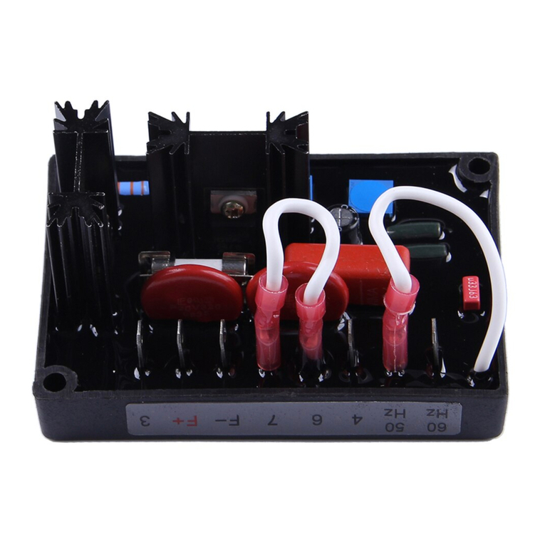
Basler SR6A User manual

INSTRUCTION MANUAL
FOR
SR6A & SR9A
Voltage Regulator
Part Number: 9017700XXX
Publication: 9017700991
Revision: J Jul-13
CALL US TODAY
1-888-POWER-58
REQUEST A QUOTE
SHOP ONLINE
www.genpowerusa.com
CALL US TODAY
1-888-POWER-58
REQUEST A QUOTE
SHOP ONLINE
www.genpowerusa.com

CALL US TODAY
1-888-POWER-58
REQUEST A QUOTE
SHOP ONLINE
www.genpowerusa.com
CALL US TODAY
1-888-POWER-58
REQUEST A QUOTE
SHOP ONLINE
www.genpowerusa.com

Preface
This instruction manual provides information about the installation and operation of the SR6A & SR9A
Voltage Regulator. To accomplish this, the following information is provided:
•General information
•Mounting
•Operation
•Troubleshooting
Conventions Used in this Manual
Important safety and procedural information is emphasized and presented in this manual through
warning, caution, and note boxes. Each type is illustrated and defined as follows.
Warning!
Warning boxes call attention to conditions or actions that may cause
personal injury or death.
Caution
Caution boxes call attention to operating conditions that may lead to
equipment or property damage.
Note
Note boxes emphasize important information pertaining to installation
or operation.
CALL US TODAY
1-888-POWER-58
REQUEST A QUOTE
SHOP ONLINE
www.genpowerusa.com
CALL US TODAY
1-888-POWER-58
REQUEST A QUOTE
SHOP ONLINE
www.genpowerusa.com

12570 State Route 143
Highland IL 62249-1074 USA
www.basler.com
info@basler.com
Tel: +1 618.654.2341
Fax: +1 618.654.2351
© 2013 by Basler Electric
All rights reserved
First printing: November 1975
Warning!
READ THIS MANUAL. Read this manual before installing, operating, or maintaining the SR6A & SR9A
Voltage Regulator. Note all warnings, cautions, and notes in this manual as well as on the product.
Keep this manual with the product for reference. Only qualified personnel should install, operate, or
service this system. Failure to follow warning and cautionary labels may result in personal injury or
property damage. Exercise caution at all times.
Basler Electric does not assume any responsibility to compliance or noncompliance with national code, local code,
or any other applicable code. This manual serves as reference material that must be well understood prior to
installation, operation, or maintenance.
For terms of service relating to this product and software, see the Commercial Terms of Products and Services
document available at www.basler.com/terms.
This publication contains confidential information of Basler Electric Company, an Illinois corporation. It is loaned for
confidential use, subject to return on request, and with the mutual understanding that it will not be used in any
manner detrimental to the interests of Basler Electric Company and used strictly for the purpose intended.
It is not the intention of this manual to cover all details and variations in equipment, nor does this manual provide
data for every possible contingency regarding installation or operation. The availability and design of all features
and options are subject to modification without notice. Over time, improvements and revisions may be made to this
publication. Before performing any of the following procedures, contact Basler Electric for the latest revision of this
manual.
The English-language version of this manual serves as the only approved manual version.
CALL US TODAY
1-888-POWER-58
REQUEST A QUOTE
SHOP ONLINE
www.genpowerusa.com
CALL US TODAY
1-888-POWER-58
REQUEST A QUOTE
SHOP ONLINE
www.genpowerusa.com

Revision History
The following information provides a historical summary of the changes made to this instruction manual
(9017700991 Rev J). Revisions are listed in chronological order.
Manual
Revision and Date Change
J, Jul-13 •Converted manual into new style and structure
I •This revision letter not used
A through H •No data available
—, Nov-75 •Initial release
CALL US TODAY
1-888-POWER-58
REQUEST A QUOTE
SHOP ONLINE
www.genpowerusa.com
CALL US TODAY
1-888-POWER-58
REQUEST A QUOTE
SHOP ONLINE
www.genpowerusa.com

CALL US TODAY
1-888-POWER-58
REQUEST A QUOTE
SHOP ONLINE
www.genpowerusa.com
CALL US TODAY
1-888-POWER-58
REQUEST A QUOTE
SHOP ONLINE
www.genpowerusa.com

Contents
General Information .................................................................................................................................... 1
Specifications ............................................................................................................................................ 1
Power Input*.......................................................................................................................................... 1
Output Rating......................................................................................................................................... 1
Input Sensing Voltage*(NEMA Standard) ............................................................................................ 1
Field Resistance .................................................................................................................................... 1
Temperature .......................................................................................................................................... 2
Vibration ................................................................................................................................................. 2
Mounting ................................................................................................................................................ 2
Weight.................................................................................................................................................... 2
Overall Dimensions................................................................................................................................ 2
Optional Features ...................................................................................................................................... 2
Accessories ............................................................................................................................................... 2
Model and Style Number Description........................................................................................................ 3
Principles of Operation............................................................................................................................... 5
Functional Circuits ..................................................................................................................................... 5
Application Information .............................................................................................................................. 5
Starting Large Motors or Providing Fault Current for Selective Breaker Tripping ................................. 5
Parallel Compensation .............................................................................................................................. 6
Reactive Droop Compensation (Droop)................................................................................................. 6
Reactive Differential Compensation (Cross-Current) ............................................................................ 6
Installation ................................................................................................................................................... 9
Mounting .................................................................................................................................................... 9
Interconnection ........................................................................................................................................ 11
General ................................................................................................................................................ 11
Regulator Sensing (Terminals E1, E2, and E3)................................................................................... 11
Field Power (Terminals F+ and F–) ..................................................................................................... 13
Interconnecting Regulator with Brush-Type Rotary Exciters (Terminal A–) ........................................ 13
Input Power (Terminals 3 and 4) ......................................................................................................... 13
Parallel Compensation (Terminals 1 and 2) ............................................................................................ 14
Reactive Droop Compensation (Droop) .................................................................................................. 14
Reactive Differential Compensation (Cross Current) .............................................................................. 14
Wiring....................................................................................................................................................... 18
Operation ................................................................................................................................................... 19
Operation at Reduced Speeds ................................................................................................................ 19
Voltage Shutdown ................................................................................................................................... 19
Adjustments............................................................................................................................................. 19
Stability Adjustment R4........................................................................................................................ 20
Generator Voltage Adjust Rheostat R1 ............................................................................................... 20
Nominal Voltage Range Set Adjust R3................................................................................................ 20
Wiring....................................................................................................................................................... 20
Initial Operation ....................................................................................................................................... 20
Single Unit Operation (No Load).......................................................................................................... 20
Instability .............................................................................................................................................. 21
Field Flashing .......................................................................................................................................... 21
Parallel Operation.................................................................................................................................... 22
Preliminary Instructions ....................................................................................................................... 22
Preliminary Operation .......................................................................................................................... 22
Conditions Necessary for Paralleling................................................................................................... 22
Metering ............................................................................................................................................... 22
Sequence of Operation (Parallel) ........................................................................................................ 23
Maintenance .............................................................................................................................................. 25
Preventive Maintenance .......................................................................................................................... 25
Corrective Maintenance........................................................................................................................... 25
Warranty and Repair Service .................................................................................................................. 25
CALL US TODAY
1-888-POWER-58
REQUEST A QUOTE
SHOP ONLINE
www.genpowerusa.com
CALL US TODAY
1-888-POWER-58
REQUEST A QUOTE
SHOP ONLINE
www.genpowerusa.com

Troubleshooting........................................................................................................................................ 27
Voltage Does Not Build Up to Rated Value............................................................................................. 27
Voltage Builds Up Until Relay Actuates, Then Decays ........................................................................... 28
Voltage High but Uncontrollable with Voltage Adjust Rheostat............................................................... 28
Voltage High but Controllable with Voltage Adjust Rheostat .................................................................. 28
Voltage Low and Controllable with Voltage Adjust Rheostat .................................................................. 29
Poor Regulation....................................................................................................................................... 29
Poor Voltage Stability .............................................................................................................................. 30
Voltage Recovers Slowly with Load Change........................................................................................... 31
Parallel Generators Do Not Divide Real Power Load Equally................................................................. 31
No Reactive Droop Compensation Can Be Obtained for Parallel Generators........................................ 31
Parallel Generators Do Not Divide Reactive kvar Load Equally (Circulating Reactive Current Between
Generators) ............................................................................................................................................. 32
CALL US TODAY
1-888-POWER-58
REQUEST A QUOTE
SHOP ONLINE
www.genpowerusa.com
CALL US TODAY
1-888-POWER-58
REQUEST A QUOTE
SHOP ONLINE
www.genpowerusa.com

General Information
The SR6A and SR9A Voltage Regulators precisely control the output voltage of an ac electric generating
system by controlling the amount of current supplied to the exciter (or generator) field. This includes
brushless rotary exciters, brush type rotary exciters, or direct excitation into the field of machines within
the regulator’s power rating.
The voltage regulators contain no electrolytic capacitors and are relatively unaffected by temperature,
humidity, vibration, and shock.
Specifications
Voltage Regulation......................................................... Less than ±½% (average voltage)
Response Time .............................................................. Less than 17 milliseconds
Voltage Adjust Range .................................................... ±10% of nominal voltage
Maximum Power Dissipation.......................................... 60 Watts
Parallel Compensation ................................................... 5 A at 25 VA, Droop Adjustment to 6%
Power Input*
SR6A .............................................................................. 120 Vac ±10%, 400 Hz, 840 VA†
SR9A .............................................................................. 240 Vac ±10%, 400 Hz, 1,680 VA†
*If correct voltage is not available for power input, a suitable power transformer must be selected. See
the Installation chapter.
† The actual input VA is equal to the dc current times input voltage.
Output Rating
Maximum Continuous
SR6A .............................................................................. 63 Vdc, 7 Adc
SR9A .............................................................................. 125 Vdc, 7 Adc
One Minute Forcing
SR6A .............................................................................. 90 Vdc, 10 Adc
SR9A .............................................................................. 180 Vdc, 10 Adc
Input Sensing Voltage*(NEMA Standard)
SR6A
100-110/190-200-208/220-230-240/380-400-415/500 Vac ±10% at 400 Hz
SR9A
120-139/208/240/416/480/600 Vac ±10% at 400 Hz
*Sensing voltage may be single- or three-phase.
Field Resistance
SR6A .............................................................................. 9 Ωminimum
SR9A .............................................................................. 19 Ωminimum
CALL US TODAY
1-888-POWER-58
REQUEST A QUOTE
SHOP ONLINE
www.genpowerusa.com
CALL US TODAY
1-888-POWER-58
REQUEST A QUOTE
SHOP ONLINE
www.genpowerusa.com

Temperature
Ambient Operating Temperature Range........................ –55°C to 70°C (–67°F to 158°F) at 3.5 amperes
–55°C to 55°C (–67°F to 131°F) at 7.0 amperes
Storage Temperature Range ......................................... –65°C to 100°C (–85°F to 212°F) at 3.5 amperes
Temperature Coefficient (after 20 minutes warm-up) .... ±½% for 20°C (68°F) change
Vibration
Tested to withstand 5 G’s from 20 to 260 Hz.
Mounting
Designed to operate when mounted directly on an engine generator set. It is recommended to be
mounted vertically for optimum cooling.
Weight
13 lb (5.8 kg)
Overall Dimensions
Height ............................................................................. 11.500 inches (292.10 mm)
Width .............................................................................. 8.375 inches (212.72 mm)
Depth.............................................................................. 5.000 inches (127.00 mm)
Optional Features
The internal voltage regulator optional features listed below are designated by a combination of letters
and numbers in the complete model number. See the style chart and/or contact the factory for additional
variations.
•Parallel compensation
•Voltage build-up relay
•Single- or three-phase sensing
•Sensing voltage
•Cover
•Voltage adjust rheostat
•Type of stability circuit
Accessories
The following is a partial list of accessories that are available for use with the SR6A and SR9A Voltage
Regulators.
•EMI suppression filters
•Low- and medium-voltage power isolation transformers
•Paralleling current transformers
•Voltage regulators operating from 60 hertz power on 400 hertz generators
•Wide-range voltage adjust circuit components
•Control switches
•Motor-operated controls
Information covering these accessories may be obtained by consulting the applicable instruction manual
and product bulletin, or by contacting your nearest Basler Electric Sales Representative or the factory.
CALL US TODAY
1-888-POWER-58
REQUEST A QUOTE
SHOP ONLINE
www.genpowerusa.com
CALL US TODAY
1-888-POWER-58
REQUEST A QUOTE
SHOP ONLINE
www.genpowerusa.com

If used, an external voltage adjust rheostat may be obtained from a source other than Basler Electric. This
rheostat must be a minimum of 2 watts in size. The nominal required resistance is 175 Ω. Although any
value from 150 Ωto 250 Ωmay be used, a slight change in the voltage adjust range will occur.
Model and Style Number Description
SR6A and SR9A electrical characteristics and operational features are defined by a combination of letters
and numbers that make up the style number. The model number and style number are shown in Figure 1.
Figure 1. Style Chart
CALL US TODAY
1-888-POWER-58
REQUEST A QUOTE
SHOP ONLINE
www.genpowerusa.com
CALL US TODAY
1-888-POWER-58
REQUEST A QUOTE
SHOP ONLINE
www.genpowerusa.com

CALL US TODAY
1-888-POWER-58
REQUEST A QUOTE
SHOP ONLINE
www.genpowerusa.com
CALL US TODAY
1-888-POWER-58
REQUEST A QUOTE
SHOP ONLINE
www.genpowerusa.com

Principles of Operation
Functional Circuits
Refer to the block diagram in Figure 2. The voltage regulator senses the generator voltage, compares a
rectified sample of that voltage with a reference diode (Zener) voltage, and supplies the field current
required to maintain the predetermined ratio between the generator voltage and the reference voltage.
This unit consists of five basic circuits. These are a sensing circuit, an error detector, an error amplifier, a
power controller, and a stabilization network.
Figure 2. Overall Block Diagram
Application Information
Starting Large Motors or Providing Fault Current for Selective Breaker Tripping
For generators equipped with brushless exciters or for static-excited generators, the field power is taken
from the generator output voltage. A heavy load, such as a large motor, can cause generator voltage to
decrease substantially at the first few cycles after load application. A short circuit on the generator output
could reduce the voltage from the generator to zero. Either of these conditions can cause reduction of the
available field power to a level which will not sustain generator voltage. Accessory excitation support
systems are available which take advantage of the generator line currents as a source of excitation power
during either condition.
For brush-type, rotation-excited generators, the exciter armature connections can be used as an alternate
source of excitation during either of the conditions described above to provide excitation support. See the
Installation chapter for a typical interconnection diagram. This scheme uses the other contact on the
buildup relay to connect dc voltage from the exciter armature directly to the exciter field. As an alternative,
the regulator could be used as described above.
CALL US TODAY
1-888-POWER-58
REQUEST A QUOTE
SHOP ONLINE
www.genpowerusa.com
CALL US TODAY
1-888-POWER-58
REQUEST A QUOTE
SHOP ONLINE
www.genpowerusa.com

Parallel Compensation
Parallel operation requires additional components in the regulating system. These are resistor R25,
transformer T3 and a current transformer CT1. Two of the components are included in a parallel equipped
voltage regulator. These are R25 and T3. Current transformer (CT1) is a separate item and must be
interconnected as shown in the Installation chapter.
These components allow the paralleled generators to share reactive load and reduce circulating reactive
currents between them. This is accomplished in the following manner.
A current transformer CT1 is installed in phase B of each generator. It develops a signal that is
proportional in amplitude and phase to the line current. This current signal develops a voltage across
resistor R25. A slider on R25 supplies a part of this voltage to the primary of the transformer T3. The
secondary windings of T3 are connected in series with the leads from the secondary of the sensing
transformer T1, and the sensing rectifiers located on the printed circuit board. The ac voltage applied to
the sensing rectifier bridge is the vector sum of the stepped-down sensing voltage (terminals E1 and E3)
and the parallel CT signal supplied through T3 (terminals 1 and 2). The voltage supplied to the sensing
rectifiers by the parallel CT is very small in relation to the signal supplied by the sensing voltage. The
regulator input sensing voltage (terminals E1 and E3) and the parallel compensation signal (terminals 1
and 2) must be connected to the generator system so as to provide the correct phase and polarity
relationship.
Regulators with single-phase sensing provide about 8% maximum droop while three-phase sensing
regulators provide 6% droop. When generators are paralleled on the same bus and have different type
sensing, care must be taken to compensate for these differences using the slide wire adjustment on
droop resistor R25.
When a resistive load (unity power factor) is applied to the generator, the voltage that appears across
R25 (and T3 windings), leads the sensing voltage by 90°, and the vector sum of the two voltages is nearly
the same as the original sensing voltage. Consequently, almost no change occurs in generator output
voltage.
When a lagging power (inductive) load is applied to the generator, the voltage across R25 becomes more
in phase with the sensing voltage and the combined vectors of the two voltages results in a larger voltage
being applied to the sensing rectifiers. Since the action of the regulator is to maintain a constant voltage
at the sensing rectifiers, the regulator reacts by decreasing the generator output voltage.
When a leading power factor (capacitive) load is applied to the generator, the voltage across R25
becomes out of the phase with the sensing voltage and the combined vectors of the two voltages results
in a smaller voltage being applied to the sensing rectifiers, then the regulator reacts by increasing the
generator voltage.
When two generators are operating in parallel, if the field excitation on one generator should become
excessive and cause a circulating current to flow between generators, this current will appear as a lagging
power factor (inductive) load to the generator with excessive field current and a leading power factor
(capacitive) load to the other. The parallel Compensation circuit will cause the voltage regulator to
decrease the field excitation on the generator with the lagging power factor load, and increase the field
excitation on the generator with the leading power factor load, so as to minimize the circulating currents
between the generators.
Reactive Droop Compensation (Droop)
Reactive droop compensation (droop) allows two or more paralleled generators to proportionally share
inductive loads by causing a decrease or droop in the generator system voltage.
Reactive Differential Compensation (Cross-Current)
Reactive differential compensation allows two or more paralleled generators to share inductive reactive
loads with no decrease (or droop) in the generator system output voltage. This is accomplished by the
action and circuitry described previously for reactive droop compensation, and the addition of cross-
connecting leads between the parallel CT secondary windings as shown in the Installation chapter. By
connecting the finish of one parallel CT to the start of another, a closed series loop is formed, which
CALL US TODAY
1-888-POWER-58
REQUEST A QUOTE
SHOP ONLINE
www.genpowerusa.com
CALL US TODAY
1-888-POWER-58
REQUEST A QUOTE
SHOP ONLINE
www.genpowerusa.com

interconnects the CTs of all generators to be paralleled. The signals from the interconnected CTs cancel
each other when the line currents are proportional and in phase. No system voltage decrease occurs.
These regulators provide the necessary circuit isolation so that parallel reactive differential compensation
can be used. The reactive differential circuit can be used only when all the generators connected in
parallel have identical paralleling circuits included in the loop.
Reactive differential compensation cannot be used when paralleled with the utility or other infinite (utility)
bus. When reactive differential compensation is to be used on an isolated bus that may parallel with the
utility bus, an auxiliary contact on the breaker used to connect the isolated bus to the utility bus must be
used to open the reactive differential interconnecting loop any time the isolated system is connected to
the utility. Contact Basler Electric for additional information.
CALL US TODAY
1-888-POWER-58
REQUEST A QUOTE
SHOP ONLINE
www.genpowerusa.com
CALL US TODAY
1-888-POWER-58
REQUEST A QUOTE
SHOP ONLINE
www.genpowerusa.com

CALL US TODAY
1-888-POWER-58
REQUEST A QUOTE
SHOP ONLINE
www.genpowerusa.com
CALL US TODAY
1-888-POWER-58
REQUEST A QUOTE
SHOP ONLINE
www.genpowerusa.com

Installation
Mounting
The voltage regulator should be mounted vertically for optimum cooling when operating near its full-rated
output. The regulator can be mounted in any location where the ambient temperature does not exceed its
operational limits. Due to its rugged construction, the regulator can be mounted directly on the generator.
Outline dimensions are shown in Figure 3.
Figure 3. Outline Drawing
CALL US TODAY
1-888-POWER-58
REQUEST A QUOTE
SHOP ONLINE
www.genpowerusa.com
CALL US TODAY
1-888-POWER-58
REQUEST A QUOTE
SHOP ONLINE
www.genpowerusa.com

The outline drawing for the voltage adjust rheostat (Basler P/N: 03456) is shown in Figure 4.
Figure 4. Outline Drawing - Voltage Adjust Rheostat (Basler P/N: 03456)
CALL US TODAY
1-888-POWER-58
REQUEST A QUOTE
SHOP ONLINE
www.genpowerusa.com
CALL US TODAY
1-888-POWER-58
REQUEST A QUOTE
SHOP ONLINE
www.genpowerusa.com

The outline drawing for the paralleling rheostat (Basler P/N: 03469) is shown in Figure 5.
Figure 5. Outline Drawing - Paralleling Rheostat (Basler P/N: 03469)
Interconnection
Caution
Meggers and high potential test equipment must not be used.
Incorrect use of such equipment could damage the semiconductors
contained in the regulator.
General
The regulator must be connected to the generator system as instructed in this chapter and as shown in
the basic interconnection diagrams (Figure 7 and Figure 8). A minimum of 16 AWG (1.29 mm) wire
should be used for all connections to the regulator.
Regulator Sensing (Terminals E1, E2, and E3)
Caution
The SR6A & SR9A Voltage Regulators are factory preset for 120 Vac
sensing.
The voltage regulator contains an internal sensing transformer(s) T1 (T2) provided with taps for various
input sensing voltages. These sensing voltages are: 120, 208, 240, 416, 480, and 600 Vac (refer to
Figure 6). The model number of the unit designates single-phase (T1) or three-phase (T1 and T2)
sensing. For operation with generator voltages above 600 Vac, a potential transformers(s) must be used
to supply the regulator sensing voltage. The regulator sensing circuit load is less than 10 VA and correct
polarity must be maintained to the regulator sensing input.
CALL US TODAY
1-888-POWER-58
REQUEST A QUOTE
SHOP ONLINE
www.genpowerusa.com
CALL US TODAY
1-888-POWER-58
REQUEST A QUOTE
SHOP ONLINE
www.genpowerusa.com

On single-phase sensing models, the voltage sensing leads are connected to terminals E1 and E3. For
three-phase sensing, terminals E1, E2 and E3 are used. For precise voltage regulation, the sensing leads
should be connected as close as possible to the point where regulation is desired.
SR6A and SR9A Voltage Regulators are factory preset for 120 Vac sensing voltage. If the sensing
voltage needs to be changed for your application, perform the following steps.
Step 1. Remove the cover if applicable.
Step 2. Remove nine hex screws.
Step 3. Remove the printed circuit board without disconnecting the wires.
Step 4. Locate transformer(s) T1 for single-phase sensing units (T1 and T2 for three-phase sensing
units). These transformers are equipped with Faston connectors for changing sensing taps.
Step 5. For single-phase sensing units, move the wire that is factory connected to T1-120 terminal to the
T1 terminal labeled with the desired sensing voltage.
Step 6. For three-phase sensing units, move the wire at terminal T1-120 to the T1 terminal labeled with
the desired sensing voltage. Also, move the wire from terminal T2-120 to the T2 terminal labeled
with the desired sensing voltage.
Figure 6. Top View of Voltage Regulator
The voltage applied to the sensing terminals of the regulator is regulated. Therefore, it cannot correct for
voltage drop in leads that may occur at points other than where the regulator sensing leads are
connected. The leads that supply regulator sensing should not be used to supply power to any other
equipment or to the regulator power stage (terminals 3 and 4).
If the generator will be operated in parallel with other generators, the phase relationship of sensing
voltage and the paralleling current transformer is very important. (See Parallel Compensation for further
information.)
CALL US TODAY
1-888-POWER-58
REQUEST A QUOTE
SHOP ONLINE
www.genpowerusa.com
CALL US TODAY
1-888-POWER-58
REQUEST A QUOTE
SHOP ONLINE
www.genpowerusa.com
This manual suits for next models
1
Table of contents
Other Basler Controllers manuals

Basler
Basler SSR 32-12 User manual

Basler
Basler AVC63-2.5 User manual

Basler
Basler AVC63-4 User manual

Basler
Basler VR63-4A/UL User manual

Basler
Basler DGC-2020 User manual

Basler
Basler AEC 42-7 User manual

Basler
Basler DGC-2020ES Quick guide

Basler
Basler DECS-250 User manual

Basler
Basler AVC63-12A1 User manual

Basler
Basler DGC-2020ES User manual

Basler
Basler DECS-200 User manual

Basler
Basler AVC63-2 User manual

Basler
Basler VR63-4B User manual

Basler
Basler APR 63-5 User manual

Basler
Basler AVC634A-12 User manual

Basler
Basler DGC-2020ES User manual

Basler
Basler DGC-500 User manual

Basler
Basler BE2000E User manual

Basler
Basler SCP 250 User manual

Basler
Basler KR4FFX User manual