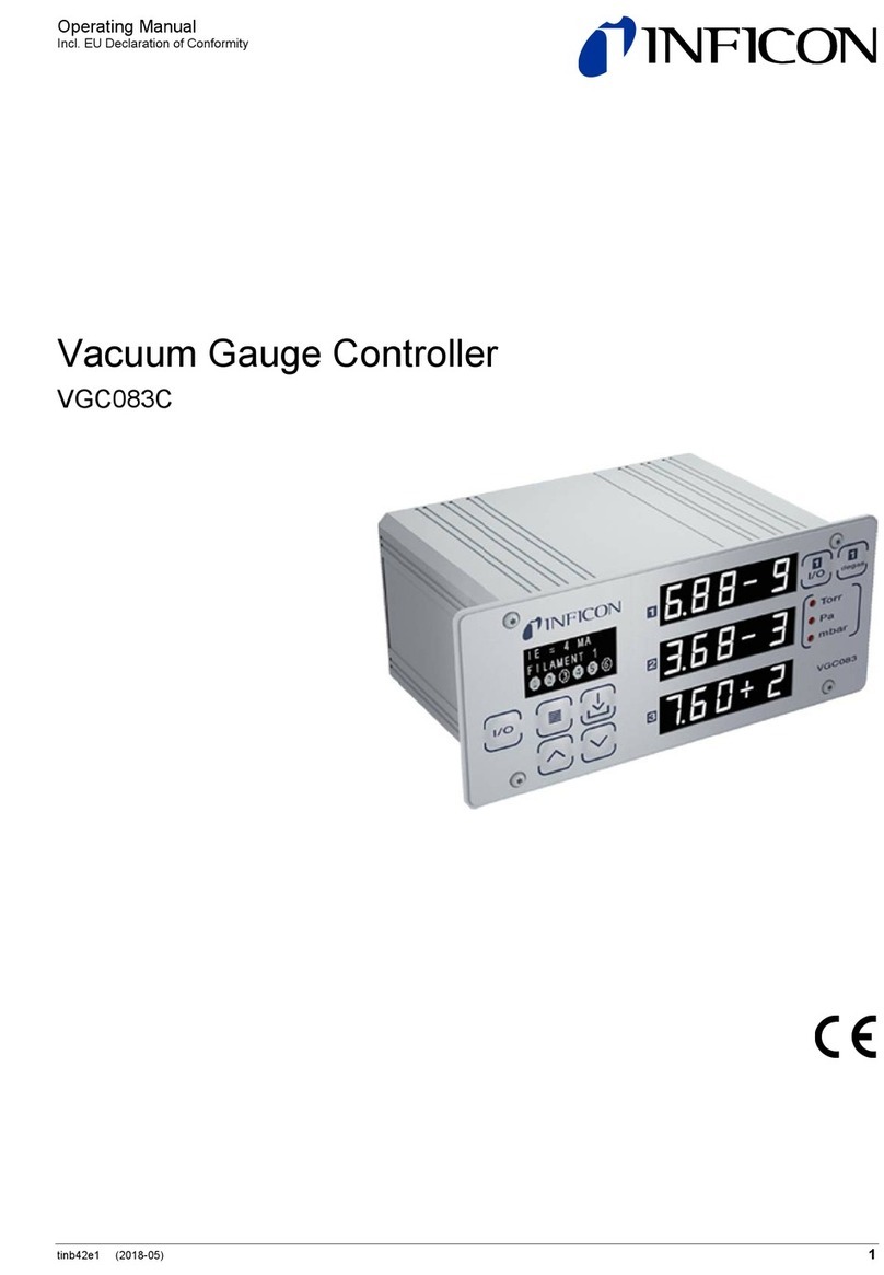
Inficon VGC083B User manual

Operating
M
Incl. EU Declar
a
tinb29e1 (201
6
Vacu
VGC08
3
M
anual
ation of Confor
m
6
-11)
um
G
3
A, VG
C
m
ity
G
aug
e
C
083B
e
Co
n
n
troll
e
r
1

2
Prod
u
V
alid
Imp
o
u
ct Identi
f
ity
rtant Use
r
f
ication
r
Informa
t
I
n
n
T
T
I
f
c
o
W
A
T
e
a
m
c
a
I
n
d
A
ti
v
p
a
N
c
u
T
s
y
I
d
p
s
e
I
d
p
m
t
ion
n
all communi
c
a
meplate:
his document
399
-
399
-
he part numb
e
not indicated
o
rrespond to
t
W
e reserve th
e
A
ll dimensions
here are ope
r
lectromechan
re a variety o
f
m
ent must tak
e
a
tion of this e
q
n
no event will
a
mages that
r
A
ny examples
v
e purposes.
B
a
rticular insta
l
c
tual use bas
e
N
o patent liabil
u
its, equipme
n
hroughout thi
s
y
mbols and s
a
d
entifies infor
m
hysical hazar
d
e
rious injury,
p
d
entifies infor
m
hysical hazar
d
m
oderate injur
y
CA
U
c
ations with I
N
t
applies to pr
o
-
700
-
701
er (PN) can b
e
otherwise in
t
t
he unit VGC
0
e
right to mak
e
are indicated
r
ational chara
c
ical equipme
n
f
uses for soli
d
e
every preca
u
q
uipment is s
a
l
INFICON be
r
esult from th
e
or diagrams i
n
Because of t
h
llation, INFIC
O
e
d on the exa
l
ity is assume
d
n
t, or softwar
e
s
manual we
u
a
fety messag
e
m
ation about
p
d
s which, if p
r
p
roperty dam
a
m
ation about
p
d
s which, if p
r
y
, property da
U
TION
N
FICON, plea
o
ducts with p
a
(VGC083A, use
w
(VGC083B, use
w
e
taken from
t
t
he legends, t
h
0
83A.They ap
p
e
technical ch
a
in mm.
c
teristic differ
e
n
t. Because o
f
d
state equip
m
u
tion and sati
s
a
fe and used
i
responsible
o
e
use or appli
c
n
cluded in thi
s
h
e many varia
b
O
N cannot as
s
mples and di
a
d
by INFICO
N
e
described in
u
se notes, no
t
e
s to make y
o
p
ractices or ci
r
ecautions are
a
ge, or econo
p
ractices or ci
r
ecautions are
mage, or eco
n
s
e specify th
e
a
rt numbers:
w
ith BAG050 and
w
ith BAG051 or B
A
t
he product n
a
h
e illustration
s
p
ly to the VG
C
a
nges withou
t
e
nces betwee
n
f
these differe
n
m
ent, all perso
s
fy themselve
s
i
n an accepta
b
o
r liable for in
d
c
ation of this
e
s
manual are
p
b
les and requ
i
s
ume respon
s
a
grams.
N
with respect
this manual.
t
ices and appl
u aware of s
a
r
cumstances
t
not taken, co
m
ic loss.
r
cumstances
t
not taken, co
n
omic loss.
tinb29e
1
e
information
o
PGEG050)
AG052/053 and
P
a
meplate.
s
in this docu
m
C
083B by an
a
t
prior notice.
n solid state
e
n
ces, and be
c
o
ns that apply
s
that the inte
b
le manner.
d
irect or cons
e
e
quipment.
p
rovided solel
irements imp
o
s
ibility or liabil
i
to use of info
r
l
y internation
a
a
fety consider
a
t
hat can caus
e
o
uld result in d
t
hat can caus
e
o
uld result in
m
1
(2016-11) VGC083A_B.
o
o
n the produc
t
P
EG050)
m
ent
logy.
e
quipment an
d
c
ause there
this equip-
nded appli-
e
quential
y for illustra-
o
sed on any
i
ty for any
r
mation cir-
a
lly recognize
d
a
tions.
e
electrical or
eath or
e
electrical or
m
inor or
o
m
t
d
d

tinb29e1 (2016-11) VGC083A_B.om 3
Identifies information that is critical for successful application and understanding of
the product.
Labels may be located on or inside the device to alert people that dangerous
voltages may be present.
INFICON assumes no liability and the warranty is rendered null and void if the end-
user or third parties
•disregard the information in this document
•use the product in a non-conforming manner
•make any kind of interventions (modifications, alterations etc.) on the product
•use the product with accessories not listed in the corresponding product docu-
mentation.
Liability and Warranty
NOTICE
SHOCK HAZARD

4tinb29e1 (2016-11) VGC083A_B.om
Contents
Product Identification 2
Validity 2
Important User Information 2
Liability and Warranty 3
1Introduction / General Information 6
1.1 VGC083A 6
1.2 VGC083B 7
2Technical Data 8
3Important Safety Information 11
3.1 Safety Precautions - General 11
3.2 Safety Precautions - Service and Operation 11
3.3 Electrical Conditions 12
3.3.1 Proper Equipment Grounding 13
3.3.2 Electrical Interface and Control 13
3.4 Overpressure and use with hazardous gases 13
3.5 Gases other than Nitrogen / air 13
4Installation 15
4.1 Mechanical Installation - Controller 15
4.1.1 Panel Mount 15
4.1.2 Rack Mount 15
4.1.3 Mechanical Installation - Ionization Gauge 17
4.1.4 Mechanical Installation - Convection Gauge 17
4.2 Electrical Installation 18
4.2.1 Grounding 18
4.2.2 Installation 19
4.2.3 Connecting the Ionization Gauge Cable 19
4.2.3.1 Standard Nude and Glass IG Cable 20
4.2.3.2 Bakeable Nude IG Cable 21
4.2.3.3 Standard IG Cable Connector Pin Out 22
4.2.4 Connecting the PGE050 - connectors labeled "2" and "3" 23
4.2.5 Power Connection 24
4.2.6 Relay Connection 24
4.2.7 Analog Output Connection 24
4.2.8 Analog Input Connection (Capacitance Diaphragm Gauges, etc.) 24
4.2.9 Digital I/O Connection 25
4.2.10 RS232 / RS485 Serial Communications Connection 26
5Operation - IG and CG 28
5.1 IG Emission Current 28
5.2 IG Degas 28
5.3 IG Filament Material Selection / Venting the Chamber 28
5.4 IG Over Pressure Shut Down 29
5.5 IG Over Temperature Shut Down 29
5.6 Convection Gauge (CG) Initial Setup 30
6Setup and programming 31
6.1 Applying Power 31
6.2 Front Panel Display 31
6.3 User Interface Basics 32
6.4 Factory-Set Default Parameters 32
6.5 Programming 34
6.5.1 SETUP UNIT 34
6.5.2 ION GAUGE 35
6.5.3 ION GAUGE 40
6.5.4 RELAYS 40
6.5.5 Analog Output 42
6.5.6 SERIAL COMM 47
6.5.7 DISPLAY 47

tinb29e1 (2016-11) VGC083A_B.om 5
7Analog Output Charts & Equations (Nitrogen/Air Only) 49
7.1 Analog Output wide range measurement for IG - CG1 0.5 - 7V
(Nitrogen / Air only) 49
7.2 Analog Output for IG LOG N - 10 (Nitrogen / Air only) 50
7.3 Analog Output for IG LOG N - 11 (Nitrogen / Air only) 51
7.4 Analog Output for IG LOG N - 12 (Nitrogen / Air only) 52
7.5 Analog Output for IG 1.8 - 8.7 V (Nitrogen / Air only) 53
7.6 Analog Output for IG LINEAR (Nitrogen / Air only) 54
7.7 Analog Output for CG1 or CG2 1 - 8 V (Nitrogen / Air only) 54
7.8 Analog Output for CG1 or CG2 0 - 7 V (Nitrogen / Air only) 56
7.9 Analog Output for CG1 or CG2 NON - LIN (Nitrogen / Air only) 57
7.10 Analog Output for CG1 or CG2 LINEAR (Nitrogen / Air only) 59
8Using the Gauge with Different Gases 60
8.1 Ion Gauge Display Correction Factors for Selected Gases 60
8.2 Effects of Different Gases on Convection Gauge Display 61
8.3 Effects of Different Gases on Analog Output 64
8.3.1 Ion Gauge Analog Output Correction Factors for Selected Gases 64
8.3.2 IG - CG1 0.5 - 7V Analog Output Correction Factors for Selected Gases 64
8.3.2.1 IG-CG1 0.5 - 7V Analog Output Correction Factors -
Ion Gauge Range 64
8.3.2.2 IG-CG1 0.5 - 7V Analog Output Correction Factors -
Convection Gauge Range 66
8.3.3 Convection gauge analog output for selected gases 66
8.3.3.1 CG1 1 - 8 V or CG2 1 - 8 V Analog Output Correction Factors -
Convection Gauge 67
8.3.3.2 CG1 0 - 7 V or CG2 0 - 7 V Analog Output Correction Factors -
Convection Gauge 68
8.3.3.3 CG1 NON-LIN or CG2 NON-LIN Analog Output Correction Factors -
Convection Gauge 69
9Communication Protocol (Serial Interface) 70
9.1 Device Specific Serial Communication Info 70
9.2 INFICON RS232 / RS485 Command Protocol Summary 70
9.3 INFICON RS232 and RS485 Command Protocol Summary 71
9.4 RS232 GP 307 and 358 Protocol 74
9.5 RS485 GP 307 and 358 Protocol 75
10 Service 77
10.1 Calibration 77
10.2 Troubleshooting - IG Operation 77
10.3 Troubleshooting - IG Error Messages 78
10.4 Clearing Error Messages - IG 78
10.5 Research Screen 78
10.5.1 Research Screen (Diagnostic Display - IG) 78
10.6 Maintenance 80
11 Repair 81
12 Accessories 81
13 Storage 82
14 Disposal 82
EU Declaration of Conformity 83
For cross-references within this document, the symbol (→XY) is used; for cross-
references to further documents listed under ‘Literature’, use is made of the symbol
(→[Z]).

6
1 I
n
1.1
V
T
c
M
n
troduct
i
V
GC083A
T
ypical Com
p
c
omplete Va
c
M
easureme
n
i
on / Ge
n
p
onents of t
h
c
uum Press
u
n
t System
n
eral Inf
o
T
s
y
•
•
•
•
1)
T
t
h
B
c
o
T
e
h
i
m
P
d
e
x
h
e
u
re
o
rmatio
n
he Vacuum
G
y
stem which i
s
The VGC0
8
One INFIC
O
ionization g
One or two
Cables to i
n
The VGC083
A
vacuum gaug
e
ypical compo
n
h
e figure belo
w
B
AG050 hot io
n
o
ntrol for up t
o
he VGC083A
ither rack or i
n
igh rack-mou
n
m
portant infor
m
P
GE050 Oper
a
e
vice you int
e
x
ternal devic
e
n
G
auge Control
s comprised
o
8
3A Vacuum
G
O
N BAG050
n
g
auge or othe
r
INFICON P
G
n
terconnect t
h
A
will also operate
e
head.
n
ents of the c
o
w
. The VGC0
8
n gauge hea
d
o
two enhanc
e
, a controller
u
n
strument pa
n
n
t panels are
a
m
ation about
t
a
ting Manual.
e
nd to connec
t
e
s and cables
l
er VGC083A
o
f the followin
g
G
auge Contr
o
n
ude UHV EB
-
r
brands of nu
d
G
E050 convec
t
h
e VGC083A
a
the Granville-Phi
l
o
mplete vacu
u
8
3A provides
d
(IG). Additio
n
e
d convection
u
nit capable o
n
el mountable
a
vailable to
m
t
he PGE050
c
Read the Op
e
t
to the VGC0
that the VGC
0
is a vacuum
p
g
:
o
ller
-
degas Bayar
d
d
e UHV EB-d
e
t
ion enhance
d
a
nd point-of-u
s
lips
®
Convectron
®
u
m measure
m
p
ower and op
n
ally, it provid
e
gauges (CG)
V
G
C
o
B
A
P
G
1
&
f
controlling
m
.
Optional ind
u
ount the unit i
c
onvection ga
u
e
rating Manu
a
8
3A prior to c
o
0
83A is inten
d
tinb29e
1
p
ressure mea
s
d
-Alpert hot c
a
egas B-A ga
u
d
pirani heads
se devices
®
convection enh
a
m
ent system
a
p
erating contr
o
e
s power and
)
.
G
C083A Vac
o
o
ntroller
A
G050 Ion G
a
G
E050 Conve
c
&
2 (CVG 1 &
m
ultiple gauge
u
stry standar
d
i
nto rack encl
o
u
ge please re
a
ls in their ent
i
onnecting an
d
d
ed to be use
d
1
(2016-11) VGC083A_B.
o
s
urement
a
thode
ges
1)
a
nced pirani
re shown in
o
l for the
operating
om Gauge
uge
c
tion Gauges
2)
heads, is
d
19-inch, 2U
o
sures. For
f
er to the
i
rety for any
d
using the
d
with.
o
m

tinb29e1 (2016-11) VGC0
1.2
V
GC
0
Typic
a
compl
e
Meas
u
83A_B.om
0
83B
a
l Compone
n
e
te Vacuum
u
rement Sys
t
n
ts of the
Pressure
t
em
The Va
c
system
•The
•On
e
cath
gau
g
•On
e
•Cab
1)
The
V
vacu
u
Typical
the figu
r
BAG05
1
and op
e
The VG
either r
a
high ra
c
importa
n
PGE05
0
device
y
externa
l
c
uum Gauge
C
which is com
p
VGC083B V
a
e
INFICON B
A
h
ode ionizatio
n
g
es
e
or two INFIC
les to interco
n
V
GC083B will als
o
u
m gauge head.
components
o
r
e below. The
1
or BAG052
/
e
rating control
or
G
C083B, a co
n
a
ck or instrum
c
k-mount pan
e
nt information
0
Operating
M
y
ou intend to
c
l devices and
C
ontroller VG
p
rised of the f
o
a
cuum Gauge
A
G051 nude o
r
n
gauge or ot
h
ON PGE050
c
n
nect the VG
C
o
operate the Gra
n
o
f the comple
t
VGC083B pr
o
/
053 ion gau
g
for up to two
n
troller unit ca
p
ent panel mo
u
e
ls are availa
b
about the P
G
M
anual. Read
t
c
onnect to th
e
cables that th
C
083B is a v
a
o
llowing:
Controller
r
BAG052 / 0
5
h
er equivalent
c
onvection en
C
083B and po
n
ville-Phillips
®
Co
t
e vacuum m
e
o
vides power
g
e heads (IG)
.
enhanced co
n
p
able of contr
o
u
ntable. Optio
b
le to mount t
h
G
E050 convec
t
t
he Operating
e
VGC083B p
r
e VGC083B i
s
a
cuum pressu
5
3 glass I
2
R
B
brands of I
2
R
n
hanced piran
i
int-of-use de
v
o
nvectron
®
conve
c
e
asurement s
y
and operatin
g
.
Additionally,
n
vection gau
g
VGC083
Controll
e
BAG051
BAG052
PGE050
1 & 2 (C
V
r
olling multipl
e
o
nal industry s
h
e unit into ra
c
c
tion gauge pl
e
Manuals in t
h
r
ior to connec
t
s
intended to
re measurem
e
B
ayard-Alpert
h
R
glass/nude
B
i
heads
1)
v
ices
c
tion enhanced pi
r
y
stem are sho
w
g
control for e
i
it provides p
o
g
es (CG).
B Vacoom G
a
e
r
Ion Gauge
or
/ 053 Ion Ga
u
Convection
G
V
G 1 & 2)
e
gauge head
s
tandard 19-in
c
c
k enclosures
e
ase refer to t
h
eir entirety fo
t
ing and usin
g
be used with.
7
e
nt
h
ot
B
-A
r
ani
w
n in
i
ther the
o
wer
a
uge
u
ge
G
auges
s
, is
c
h, 2U
. For
he
r any
g
the

8tinb29e1 (2016-11) VGC083A_B.om
2 Technical Data
VGC083A
with BAG050
with PGE050
2×10-11 …1×10⁻³ Torr
1×10⁻⁴ …1000 Torr
VGC083B
with BAG051 or BAG052/053
with PGE050
4×10⁻¹⁰ …1×10⁻³ Torr
1×10⁻⁴ …1000 Torr
Units of measurement Torr, mbar, Pa (user selectable)
Pressure indication LED - 3 independent pressure display
channels, 3 digit plus 2 digit exponent per
channel
Set-up & programming screen OLED - displays state of all setpoint relays, IG
emission current, error messages for fault
conditions
VGC083A
(IG)
powers & operates one INFICON BAG050
nude UHV EB-Degas B-A hot cathode or other
equivalent brands
, (CG) powers & operates up to 2 INFICON PGE050
convection or Granville-Phillips®(GP)
Convectron®
VGC083B
(IG)
powers & operates one BAG051 or BAG052 /
053 or other equivalent brands of glass or nude
I2R B-A hot cathode
, (CG) powers & operates up to 2 INFICON PGE050
convection or Granville-Phillips®(GP)
Convectron®
IG sensor on/off, degas on/off and emission current can all be controlled via front
panel soft-keys, remote input signals (digital I/O) or serial communications. IG sen-
sor can also be automatically turned on/off using measurements from one of the
user selectable convection or alternate gauges.
IG sensor on/off, degas on/off and emission current can also be set by applying
momentary continuity to ground. Also the 9-pin D-sub remote input DIGITAL I/O
connector provides pin-pin compatible signals with the GP 358 controller as well as
compatible signals with the GP 307.
Number 6
single-pole, double-throw (SPDT), user as-
signable to any of the gauges
Contact rating 5 A at 30 V (dc), 5 A at 250 V (ac), resistive
load
Measurement range
Display
Functionality
IG sensor control
IG remote input signals
(digital I/O)
Setpoint relays

tinb29e1 (2016-11) VGC083A_B.om 9
IG analog output
Log-linear
0 … 10 V (dc), 1 V/decade, or
1.7 … 9.3 V (dc) (nominal 1.8 … 8.7 V (dc)),
0.8 V/decade
Linear 0 … 10 V (dc) (useable over 3 decades)
Combination IG + CG analog
Log-linear
0.5 … 7 V (dc), 0.5 V/decade
CG analog output
Log-linear
1 … 8 V (dc), 1 V/decade, or
0 … 7 V (dc), 1 V/decade
Linear 0 … 10 V (dc) (useable over 3 decades)
Non-linear analog S-curve 0.375 … 5.659 V (dc)
CDG one 0 … 10 V (dc) analog input signal from a
CDG when used as an alternate gauge to CG2,
or analog input from one of the following
INFICON modules: PGE300, PGE500,
BAG300
Protocol RS485 / RS232 - ASCII protocol
IG sensor on/off status message is displayed on the front panel, by serial commu-
nications and by SPDT relay (DIGITAL I/O Connector) rated at 1 A at 30 V (dc)
resistive, or 1 A at 30 V (ac) non-inductive.
IG degas on/off status or IG error conditions are displayed on the front panel, by
serial communications and by an open collector transistor output (ground emitter)
rated at 40 V max. VCE, 50 mA IC max.
IG filament switching User selectable between filament 1 or 2 using
the front panel soft-keys or RS232 / RS485
serial comm
IG emission current 100 μA, 4 mA, 10 mA or automatic switching of
emission current (auto ranging)
IG degas 40 W, resistive
IG overpressure protection
(turns ion gauge off at the
following factory default settings)
1 × 10⁻³ Torr at 100 μA emission current
5 × 10⁻⁴ Torr at 4 mA emission current
1 × 10⁻⁴ Torr at 10 mA emission current
Temperature
Operation
Storage
0 … +40 °C
–40 … +50 °C
Relative humidity 0 … 95, non-condensing
Altitude
Operating
Storage
max. 2500 m (8200 ft.)
max. 12500 m (41000 ft.)
Pollution degree II
Degree of protection IP20
Housing aluminum extrusion - black powder paint finish
Analog output
Analog input
Serial communications
Status output
IG (Ionization Gauge)
Ambience
Housing

10
M
D
i
V
G
W
V
G
ains specifi
c
i
mensions
G
C083A, V
G
W
eight
G
C083A, V
G
c
ations
G
C083B
G
C083B
V
C
m
0
V
oltage
C
onnectors
IG & CG
Digital I/O
Serial com
m
RS23
2
RS48
5
analog I/O,
power
m
m (inch)
.7 kg (1.7 lb.)
m
unications
2
5
setpoint rela
y
20 …
2
power
y
s,
gauge
9-pin
D
9-pin
D
9-pin
D
plugg
a
includ
e
2
8 V (dc), 20
0
reversal and
cable assem
b
D
-sub male
D
-sub female
D
-sub male
a
ble terminal
b
e
d)
tinb29e
1
0
W protected
transient ove
r
blies provide
d
b
lock (mating
1
(2016-11) VGC083A_B.
o
against
r
-voltages
d
by INFICON
connectors
o
m

tinb29e1 (2016-11) VGC0
3 Impo
3.1 Safe
t
Gen
e
3.2 Safe
t
Serv
i
83A_B.om
rtant Sa
f
t
y Precau
t
e
ral
t
y Precau
t
i
ce and O
p
f
ety Info
r
t
ions -
t
ions -
p
eration
r
mation
INFICO
provide
d
this ma
n
To avoi
ment.
F
bodily
h
Failure
t
and int
e
tomer's
Althoug
INFICO
operati
o
installat
This de
v
Hazard
o
product
tection
o
provide
d
W
A
the pro
d
Do not
m
INFICO
service
use this
W
A
perform
After se
service
specifie
d
shock o
product
To redu
moistur
e
not spill
have b
e
duct if i
t
Due to
t
is possi
b
that the
equipm
e
has be
e
Ensure
ground.
Ensure
electric
a
Use a p
power
s
N has design
e
d
it is installe
d
n
ual. Please
r
i
d serious inj
F
ailure to co
m
h
arm, includ
i
t
o comply wit
h
e
nded use of t
failure to co
m
h every atte
m
N cannot anti
c
o
n, or mainte
n
ion and use
o
v
ice meets F
C
o
us voltages
a
should never
o
f the operato
d
.
A
RNING! Th
d
uct enclosur
e
m
odify this pr
o
N service trai
n
and repair ce
n
s
product if un
a
A
RNING! S
o
ing any servi
c
e
rvicing this pr
person. Whe
n
d by INFICO
N
o
r other hazar
d
will void the
w
ce the risk of
e
. These pro
d
any type of li
q
e
en damaged.
t
is damaged.
t
he possibility
ble that the p
r
product be p
e
e
nt grounding
e
n compromis
e
the enclosur
e
that the vacu
u
a
lly grounded
.
p
ower source
o
s
upplies.
WARNI
N
e
d and tested
d
and operate
d
r
ead and foll
o
ury or death
,
m
ply with the
s
i
ng death, an
h
these warni
n
his instrumen
t
m
ply with thes
e
m
pt has been
m
c
ipate every
c
n
ance of the
m
f this product,
C
C part 15 re
q
a
re present wi
be operated
w
r from accide
n
ere are no op
e
e
. Refer servi
c
o
duct or subs
t
n
ed personne
n
ter to ensur
e
a
uthorized m
o
o
urce power
m
c
ing.
o
duct, ensur
e
n
replacemen
t
N
Substitution
s
d
s. Use of un
a
w
arranty.
fire or electri
c
d
ucts are not
w
q
uid onto the
s
Immediately
of corrosion
w
r
oduct’s safet
y
e
riodically ins
p
. Do not use i
f
e
d.
e
of the unit is
u
m port on w
h
o
f 20 … 28 V
N
G
this product t
o
d
within the st
r
o
w all warnin
follow the s
a
s
e safety pr
o
d
or propert
y
n
gs violates t
h
t
. INFICON di
s
e
instructions.
m
ade to consi
d
c
ontingency th
m
odule. If you
h
please conta
q
uirements for
th this produ
c
w
ith the cove
r
n
tal contact w
i
e
rator service
c
ing to service
t
itute any part
s
l. Return the
p
e
that all safet
y
o
difications ha
m
ust be remov
e
that all safet
y
t
parts are req
s
of non-quali
f
a
uthorized pa
r
shock, do no
t
w
aterproof an
d
s
e products.
D
c
ontact INFI
C
w
hen used in
c
y
could be co
m
p
ected for so
u
f
the equipme
connected di
r
h
ich the vacuu
(
dc), 200 W o
r
o provide saf
e
rict safety gui
d
gs and instr
u
a
fety inform
a
o
cedures co
u
y
damage.
h
e safety stan
d
sclaims all lia
b
d
er most pos
s
h
at arises fro
m
have any que
a
ct INFICON.
r
an unintenti
o
c
t during norm
r
s removed u
n
w
ith hazardous
e
able parts or
a
e
trained pers
o
s
without aut
h
p
roduct to an
y
features are
a
ve been mad
e
ed from the p
r
y
checks are
m
q
uired, ensure
f
ied parts ma
y
r
ts or modific
a
o
t expose this
d
careful atte
n
D
o not use the
C
ON to arrang
c
ertain enviro
n
m
promised ov
u
nd electrical
c
e
nt grounding
o
r
ectly to a go
o
u
m gauge sen
s
r use INFIOC
N
e
and reliable
d
elines provi
d
u
ctions.
a
tion in this
d
ld result in s
e
d
ards of insta
l
b
ility for the c
u
s
ible installati
o
m
various inst
a
s
tions about t
h
o
nal radiator,
c
al operation.
T
n
less equivale
internal volta
a
djustments i
n
o
nnel.
h
orization of q
u
I
NFICON qua
maintained.
D
e
.
r
oduct prior t
o
m
ade by a qu
a
that the part
s
y
result in fire,
a
tions made t
o
product to rai
n
n
tion must be
p
se products i
f
e
return of th
e
n
mental cond
i
e
r time. It is i
m
c
onnections a
o
r electrical i
n
o
d quality eart
h
s
ors are mou
n
N
series optio
11
service,
d
ed in
d
ocu-
e
rious
l
lation
u
s-
o
ns,
a
llations,
h
e safe
c
lass A.
T
he
nt pro-
ges is
n
side
u
alified
lified
D
o not
o
a
lified
s
are
electric
o
this
n
or
p
aid to
f
they
e
pro-
i
tions, it
m
portant
nd
n
sulation
h
n
ted is
nal

12
3.3
E
E
lectrical
N
Conditio
n
T
T
i
n
v
i
b
It
n
e
D
C
t
o
I
f
c
o
•
•
•
D
w
E
D
D
h
N
w
o
f
l
e
b
I
f
o
e
x
t
a
m
T
s
o
a
c
h
e
S
A
fi
e
e
a
c
o
a
g
c
o
t
a
t
h
N
OTICE
n
s
urn off power
urn off power
n
g normally a
c
i
ce personnel
y
this operati
n
is important t
e
ctions and e
q
lectrical insul
a
D
o not use if t
h
C
ontact INFIC
O
o
INFICON fo
r
measured pr
e
o
nditions, the
The pressu
The pressu
The pressu
D
uring the De
g
w
ill turn off but
E
nsure vacuu
m
D
egas of the B
D
o not attempt
e
re.
N
ever use an
a
w
hen the Ion
G
f
other gauge
s
e
ading to fila
m
e
fore pressur
e
you are usin
g
perating the i
o
x
tended perio
a
in emission
c
m
inated by res
he most com
m
o
r or head el
e
ll possible ind
h
aracterized
a
lectrodes, or
B
S
ensors that f
a
A
fter servicing
e
d service pe
r
WARNIN
G
ning electrica
l
re maintained
o
ntact with th
e
gaseous env
i
rounded con
d
o
ming in cont
a
a
ge potential.
h
e gas inside
t
to the unit be
to the unit if
a
c
cording to thi
s
for any servi
c
n
g manual.
t
hat the produ
c
quipment gro
u
a
tion has bee
n
h
e unit has be
e
O
N for return
a
r
evaluation.
e
ssure excee
d
ion gauge wil
re exceeds 1.
re exceeds 5.
re exceeds 1.
g
as cycle, if th
the filament
w
m
level is less
B
AG05x serie
s
t
to turn the I
G
a
uxiliary or co
n
G
auge filamen
s
may not all
o
m
ent damage.
e
is allowed t
o
g
dual filamen
o
n gauge fila
m
o
d of time ma
y
c
urrent in appl
idual applicat
i
m
on cause of
e
ctrodes. Nois
ications of ga
a
s either: A) a
B
) an accumu
a
il due to cont
a
these produc
t
r
son
G
! When high
l
shock hazar
d
d
at earth grou
e
gas contain
e
ironment ma
y
d
uctor of elect
r
a
ct with an e
x
This conditio
n
t
he vacuum c
h
f
ore attempti
n
a
cable or plu
g
s
instruction
m
c
e or troubles
h
c
t be periodic
a
u
nding. Do n
o
n
compromis
e
e
n dropped o
r
a
uthorization
a
d
s the thresh
o
l turn off:
00 × 10
-3
Tor
r
00 × 10
-4
Tor
r
00 × 10
-4
Tor
r
e measured
p
w
ill remain tur
n
than 5.00 x 1
0
s
ionization ga
G
on if the pre
s
n
vection gau
g
t in use is co
n
o
w for timely t
u
Always turn
o
o
rise above 1
t IGs, it is hig
h
m
ents 1 and 2
y
result in failu
i
cations wher
e
i
on or proces
s
all vacuum g
a
y or erratic re
a
u
ge contamin
a
chemical rea
c
lation of mate
a
mination are
t
s, ensure tha
t
voltage is pr
e
d
may exist u
n
nd potential.
T
e
d in vacuum
y
couple dang
e
r
icity. A perso
x
posed, ungro
u
n
applies to al
l
h
amber (vacu
n
g to service t
h
g
is damaged
o
m
anual. Cont
a
h
ooting condit
a
lly inspected
t use if the eq
d.
r
the enclosur
e
a
nd instructio
n
o
lds that are d
r
at 100 μA e
m
r
at 4 mA emi
s
r
at 10 mA e
m
p
ressure exce
e
n
ed on.
0
-5
Torr befor
e
uge heads.
s
sure is near t
g
e to automati
c
n
structed of tu
u
rn off of the t
ff the IG filam
.00E-03 (1.0
0
h
ly recommen
.
An inactive f
i
re of that fila
m
e
the filament
s
related che
m
a
uge failures i
s
a
dings and to
t
a
tion. Conta
m
c
tion of proce
s
rial on the he
a
not covered
u
t
all safety ch
e
e
sent in any v
a
n
less all expo
s
T
his applies t
o
chambers. A
n
e
rous high vol
n
could be se
r
u
nded electri
c
products tha
t
um/pressure
c
tinb29e
1
h
e controller.
or the produc
t
a
ct qualified I
N
t
ion that may
n
for sound el
e
q
uipment grou
e
has been d
a
ns for returni
n
d
efined under
t
m
ission curre
n
s
sion current.
m
ission curren
t
e
ds 1.00 × 10
e
attempting t
o
t
he threshold
l
c
ally turn off t
u
ngsten. The
t
ungsten fila
m
m
ent (tungsten
0
× 10
-3
) Torr.
n
ded to period
f
ilament not o
p
m
ent to establ
i
coating may
b
m
istries.
s contaminati
o
t
al gauge he
a
m
ination can g
e
ss gases with
a
d (sensor) el
u
nder warrant
e
cks are mad
e
a
cuum syste
m
s
ed electrical
o
all products
n
electrical di
s
l
tage directly
t
riously injure
d
c
al conductor
a
t
may come i
n
c
ontainment
v
1
(2016-11) VGC083A_B.
o
t
is not operat
N
FICON ser-
n
ot be covere
d
e
ctrical con-
nding or
a
maged.
n
g the product
t
he following
n
t.
t
.
-4
Torr, Dega
s
o
initiate
l
imits defined
h
e Ion Gauge
r
esponse tim
e
m
ent possibly
)
manually
ically alternat
e
p
erating for a
n
i
sh and main-
b
ecome cont
a
o
n of the sen
-
d failures are
e
nerally be
head / sens
o
e
ctrodes.
y
.
e
by a quali-
m
, a life threat
-
conductors
t
hat come in
s
charge within
t
o any un-
d
or killed by
a
t high vol-
n
contact with
v
essel).
o
m
-
d
s
e
e
n
a
-
-
o
r
-

tinb29e1 (2016-11) VGC0
3.3.1 Pro
p
Gro
u
3.3.2 Ele
c
Con
3.4 Over
p
with
h
3.5 Gas
e
Nitro
83A_B.om
p
er Equip
m
u
nding
c
trical Inte
r
trol
pressure
a
hazardou
s
e
s other t
h
gen / air
m
ent
r
face and
a
nd use
s
gases
h
an
W
A
present
which t
h
ground
e
groundi
n
intende
d
any co
n
earthin
g
pressur
e
W
A
harm,
s
trical d
i
It is the
and an
y
are use
d
any sig
n
your sy
s
taken t
o
W
A
pressu
r
system
In case
s
implem
e
an auto
m
pressur
e
The va
c
pressur
e
sure ins
an isola
sure co
n
lower; f
o
the gau
g
correct
e
C
A
to incr
e
sure si
d
may ca
into th
e
flamm
a
of the
v
ment, c
expose
pressu
r
W
A
without
INFICO
Do not
a
unless
y
analog
o
when u
s
W
A
of flam
m
of expl
o
incand
e
an expl
o
A
RNING! Ha
z
in many vac
u
h
e ion gauge
a
e
d. Consult a
q
ng. Proper gr
o
d
operation o
f
n
trol module
m
g
conductor.
U
e
measurem
e
A
RNING! In
o
s
hield all con
i
scharges in
user’s respo
n
y
connections
d
in a safe m
a
n
als to autom
a
s
tem design
a
o
prevent injur
A
RNING! In
s
r
e inside you
m
component
s
s
where an e
q
e
nt fail-safe s
y
matic backfill
o
e
s if the pres
s
c
uum gauge h
e
s above 20
p
s
ide the senso
a
tion valve or
p
n
ditions. Wit
h
o
r example, a
g
e tube from
t
e
d barometric
A
UTION! If t
h
e
ase above l
o
d
e), vacuum
f
use leaks th
a
e
atmospher
e
a
ble gases ar
e
v
acuum/pres
s
c
ould cause
b
e
the gauge t
u
r
e when usin
A
RNING! Do
referring to c
o
N gauges an
d
a
ttempt to us
e
y
ou have appl
o
utput to dete
s
ing convecti
o
A
RNING! Do
m
able gases,
v
o
sive or comb
u
e
scent temper
a
o
sion which c
o
z
ardous volta
g
u
um processe
s
a
nd the conv
e
q
ualified Elec
t
o
unding of yo
u
f
the equipme
n
m
ust be conne
c
U
se a ground l
e
nt devices if
n
o
rder to prot
e
ductors whi
c
or around th
e
n
sibility to ens
u
made to exte
r
a
nner. Always
a
te your proc
e
a
nd ensure sa
f
y
and propert
y
s
tall suitable
r
vacuum ch
a
s
are capable
uipment failu
r
y
stem operati
o
o
peration wh
e
s
ure relief dev
i
e
ads used wi
t
p
sia (1000 tor
r
r. If your cha
m
p
ressure relie
f
h
some fittings
quick-conne
c
t
he vacuum c
h
(atmospheric
)
h
e internal pr
e
o
cal uncorre
c
f
ittings may
r
a
t would allo
w
e
of the surro
e
examples
o
s
ure contain
m
b
odily injury
a
u
be internal
v
g hazardous
not attempt t
o
o
rrection fact
o
d
modules ar
e
e
with other g
a
ied correction
rmine the tru
e
o
n gauges to
m
not use the I
G
v
apors or fum
u
stible gases
o
a
tures and co
o
uld result in
s
g
es that could
s
. Verify that t
e
ction gauges
t
rician if you a
u
r equipment
i
n
t. The vacuu
m
c
ted directly t
o
ug on the vac
n
ecessary.
e
ct personne
l
c
h are subjec
t
e
vacuum sy
s
u
re that the el
r
nal devices,
f
double chec
k
e
ss. Perform
a
f
eguards and
y
damage.
p
rotective d
e
a
mber to les
s
of withstan
d
e could caus
e
o
n. For exam
p
e
re a malfunct
i
ce was not in
s
h this product
r
); DO NOT e
x
m
ber goes to
h
device to pro
t
, actual safe
o
t
, O-ring com
p
h
amber fitting
w
)
pressure.
e
ssure of a v
c
ted baromet
r
r
elease and
p
w
the gas ins
i
u
nding envir
o
o
f hazardous
g
m
ent vessel i
n
a
nd possible
v
olume to pre
gases.
o
use with gas
e
r data tables.
calibrated fo
r
a
ses such as
a
factors to bo
t
e
measured p
r
m
easure pres
s
G
in an explos
i
e
s. Do not us
e
o
r gas mixtur
e
uld become a
s
erious injury
o
seriously inju
t
he vacuum c
o
are mounted
a
re in doubt a
b
is essential f
o
m gauge hea
d
o
a good qual
c
uum connecti
l from electri
c
t to potentia
l
stem.
ectrical signa
l
f
or example, r
k
the system
s
a
hazardous o
personnel sa
f
e
vices that w
i
s
than what t
h
d
ing.
e
a hazardous
p
le, use a pre
s
ion could res
u
s
talled on the
t
are not inten
d
x
ceed 35 psig
h
igher pressu
tect the gaug
e
o
verpressure
c
p
ression fittin
g
with only a fe
w
v
acuum gaug
e
r
ic pressure
(
p
ossible over
ide the gaug
e
o
nment. To
x
gases that if
n
to the atmo
s
damage to e
e
ssure above
es other than
r
direct reado
u
a
rgon (Ar) or
c
t
h the display
e
r
essure. This
i
s
ure of gases
ive atmosphe
r
e
the IG to m
e
e
s. The sens
o
a
n ignition sou
or death.
re or cause d
e
o
nnection por
t
are electricall
y
b
out your equi
o
r safety as w
e
d
s and enclos
ity equipment
on flange of t
h
c shock and
high voltag
e
l
s from this pr
o
e
lays and sol
e
s
et-up before
u
peration anal
y
f
ety measure
s
i
ll limit the le
v
h
e vacuum c
h
condition, al
w
s
sure relief d
e
u
lt in high inte
r
chamber.
d
ed for use at
(< 2 ½ bars)
p
res, you shou
e
tube from o
v
c
onditions ma
y
g
may forcibly
w
psi over loc
a
e
device is a
l
(
atmospheri
c
p
ressure co
n
e
tube to rel
e
x
ic, pyrophor
i
allowed to le
s
pheric envi
r
q
uipment. N
local atmos
p
nitrogen (N
2
)
u
t of nitrogen
o
c
arbon dioxid
e
e
d pressure a
n
i
s particularly
other than N
2
r
e or in the pr
e
e
asure the pr
e
o
r filaments o
p
rce. This coul
d
13
e
ath are
t
s on
y
pment
e
ll as
ure of
h
e
bodily
e
elec-
o
duct
e
noids,
u
sing
y
sis of
s
are
v
el of
h
amber
w
ays
e
vice in
r
nal
p
res-
ld install
v
erpres-
y
be
release
a
l un-
l
lowed
c
pres-
n
ditions
e
ase
i
c and
ak out
r
on-
eve
r
p
heric
or air
o
r air.
e
(CO
2
)
n
d the
critical
2
/Air.
e
sence
e
ssure
p
erate at
d
cause

14
s
e
t
h
t
h
t
e
a
o
WARNIN
G
e
nce of flam
m
h
e pressure o
f
h
e gauge nor
m
e
mperature c
o
nd gas mixtur
r death.
G
! Do not us
e
m
able gases,
v
f
explosive or
m
ally operate
s
o
uld exceed t
h
r
e. This could
e
the PGE050
v
apors or fum
e
combustible
g
s
at 125 °C, b
u
h
e ignition te
m
cause an exp
in an explosi
v
e
s. Do not us
e
g
ases or gas
m
u
t if malfuncti
o
m
perature of c
e
l
osion which
c
tinb29e
1
v
e atmospher
e
e
the PGE050
m
ixtures. The
o
n should occ
u
e
rtain combu
s
c
ould result in
1
(2016-11) VGC083A_B.
o
e
or in the pre
to measure
sensor wire i
n
u
r, the wire
s
tible gases
serious injur
y
o
m
-
n
y

tinb29e1 (2016-11) VGC083A_B.om 15
4 Installation
The unit is intended for indoor use only. The unit is offered as a space saving half
rack design. It may also be used as a bench top device or easily installed in an
instrument panel. Optional EIA-standard rack mount panels are available for either
full rack or dual, side-by-side rack mount installation. When mounting multiple units
in your rack mount enclosure or mounting the unit below other electronic equip-
ment in your rack, allow at least 1U of space (1.75 in., 45 mm) between the units to
ensure adequate ventilation.
Make a cutout in your rack panel or instrument control panel as shown in
the drawing below. Be sure to allow clearance behind the panel for the in-
strument as well as connectors and cables at the back of the instrument.
Optional EIA-standard, 19-inch, 2U height rack mount panels are available
from INFICON. The optional rack mount panels are provided with panel cut-
outs and mounting holes to allow efficient mounting of your VGC083 unit.
Drill four guide holes on each side of the panel cut out (two on each side)
with dimensions as shown in the panel cut-out drawing above.
Slide the unit into the panel hole cut-out. Guide the four studs on the back of
the unit front panel face plate thru the four holes next to the panel cut-out.
Use four # 10-32 Hex Nut (provided with instrument) to tighten the unit to
the panel.
Optional EIA-standard 19-inch wide, 2U height rack mount panels available from
INFICON (→81):
4.1 Mechanical Installation -
Controller
4.1.1 Panel Mount
Procedure
4.1.2 Rack Mount

16 tinb29e1 (2016-11) VGC083A_B.om
All dimensions in inches.
The single cut-out and dual cut-out rack mountable panels shown above are availa-
ble from INFICON. Panel color matches the front panel of VGC083 units. Screws
for mounting to rack enclosure are included.
Single cut-out panel

tinb29e1 (2016-11) VGC0
4.1.3 Mec
Ioni
z
VG
C
VG
C
4.1.4 Mec
Con
83A_B.om
c
hanical In
s
z
ation Ga
u
C
083
A
C
083B
c
hanical In
s
vection G
a
s
tallation -
u
ge
s
tallation -
a
uge
NOTIC
BA
Mount t
h
ure. Lo
n
ween y
o
pressur
e
may als
The ion
i
mount t
h
conden
s
Do not
m
Vibratio
chanica
Shield t
h
or in a
s
For ele
c
vacuu
m
proper
g
lic-type
Fittings
/
installat
Use all
m
pected
t
For mo
r
the Op
e
Mount t
h
or restri
c
proces
s
change
s
Mounti
n
and co
n
cooling,
Mount t
h
reading
1 Torr,
m
E
T
E
b
or
A
G051
he ionization
g
n
g or restricte
d
o
ur process c
h
e
changes. M
s
o cause mea
s
ization gauge
he gauge wit
h
s
ation collecti
n
m
ount the ion
i
ns may caus
e
a
l stress to co
m
he ionization
g
s
puttering sys
t
c
trical safety
p
m
chamber. W
h
g
rounding. D
o
flange clamp
s
/
Flanges - foll
o
ion and use.
metal vacuu
m
t
o be below 1
.
r
e detailed inf
o
e
rating Manu
a
he PGE050a
s
cted, small di
a
s
chamber an
d
s
.
n
g the PGE05
0
n
trol instability
such as hea
t
he PGE050w
i
errors may o
c
m
ounting pos
i
T
he VGC083
A
E
B-degas Ba
y
b
rands of equ
BAG05
2
g
auge as clo
s
d
, small diam
e
h
amber and t
h
o
unting the io
s
urement and
can be moun
h
port down to
n
g in the gau
g
i
zation gauge
e
unstable rea
m
ponents in t
h
g
auge near io
t
em.
p
urposes the
h
h
en using KF
o
not attempt t
o
s
.
o
w the fitting/
f
m
fittings with
m
.
00 × 10
-7
Tor
r
o
rmation abo
u
l for the PGE
0
s
close as po
s
a
meter tubing
d
the gauge.
T
0
too close to
a
. Do not mou
n
t
ers or air con
d
i
th its main ax
c
cur above 1
T
i
tion has little
t
A
can operate
y
ard-Alpert h
o
ivalent nude
U
2
, BAG053
e as possible
e
ter tubing wil
l
h
e gauge. Thi
s
nization gaug
e
control insta
b
t
ed in any ori
e
help minimiz
e
g
e.
where it will
b
d
ings, measu
r
h
e ionization
g
n or electron
s
h
ousing of the
f
langes, meta
o
modify your
f
lange manuf
a
m
etal seals w
h
r
(1.33 × 10
-7
m
u
t the PGE05
0
0
50.
sible to the p
r
will create a
p
T
his may caus
a
gas source
i
n
t the PGE05
0
d
itioning vent
s
is horizontal (
s
T
orr if the uni
t
t
o no effect.
one INFICO
N
o
t cathode ion
i
U
HV EB-deg
a
The VG
C
one INFI
or one B
A
enclose
d
hot cath
o
or other
b
gauges.
to the pressu
l create a pre
s
s
may cause
a
e too close to
b
ility.
e
ntation, how
e
e
the effect o
f
b
e subjected t
o
rement errors
g
auge.
s
ources such
gauge must
b
a
l clamps mus
t
r
flange in ord
e
a
cturer's reco
m
h
en operating
mbar, 1.33 ×
0
convection
g
r
essure you
w
p
ressure diffe
s
e a delay in r
e
inlet may als
o
0
near a sourc
e
s
.
see diagram
b
t
is not mount
e
N
BAG050 nu
d
i
zation gauge
a
s B-A gauge
s
C
083B can op
e
C
ON BAG05
1
A
G052/053 gl
d
I
2
R Bayard-
A
o
de ionization
b
rands of equ
re you want t
o
s
sure differen
c
a
delay in res
p
a gas source
e
ver, if possib
l
any particles
o
excessive v
i
and possible
as an electro
n
b
e grounded t
t
be used to e
e
r to use non-
m
mendations
f
pressures ar
e
10
-5
Pa).
g
auge, please
w
ant to measu
r
rence betwee
e
sponse to pr
e
o
cause meas
u
e
of heating o
b
elow). Press
u
e
d horizontall
y
17
d
e UHV
or other
s
.
e
rate
1
nude
ass
A
lpert
gauge
ivalent
o
meas-
c
e bet-
p
onse to
inlet
l
e,
or
i
bration.
me-
n
beam
o the
nsure
metal-
f
or
e
ex-
refer to
r
e. Long
n your
e
ssure
u
rement
r
u
re
y
. Below

18
4.2
E
4.2.1
E
lectrical
Groundin
Installati
o
g
M
p
D
ti
o
s
t
F
f
o
-
a
w
g
t
h
g
fi
t
p
c
o
m
t
o
t
h
e
t
h
o
n
M
ount the PG
E
a
rticles or co
n
D
o not mount t
o
ns may cau
s
t
ress to comp
o
langes/ Fittin
g
o
llowing:
NPT fittings:
W
nt compound
w
raps of pipe t
h
a
uge into the
h
e gauge.
Be sure t
h
rounded to pr
o
t
tings, especi
a
roduce a goo
d
o
nnected to.
U
m
easurement
d
o
earth groun
d
h
at you conne
a
rth ground c
o
h
e green colo
r
E
050 with por
t
n
densation fr
o
t
he PGE050
w
s
e unstable re
a
onents in the
g
s - follow the
W
hen connec
t
or wrap the t
h
hread seal ta
p
gauge port.
D
h
e vacuum g
a
otect personn
a
lly those wit
h
d
electrical co
U
se a ground
d
evice if nece
d
via a good q
ct a separate
o
nnection an
d
r
ed screw pro
v
t
down, if pos
s
o
m collecting i
n
w
here it will b
e
a
dings, meas
u
PGE050.
manufacture
r
t
ing the devic
e
h
readed porti
o
p
e such as P
T
D
o not use a
w
a
uges and the
el from shoc
k
h
O-rings whe
n
nnection bet
w
lug on the va
c
ssary. The V
G
uality equipm
e
12-AWG eart
d
the location
m
v
ided) on the
s
ible, to help
m
n
the gauge.
subjected to
u
rement error
s
r
's recommen
d
e
using a NP
T
o
n of the tubin
g
T
FE (Teflon
®
)
t
w
rench or othe
rest of your v
and injury. B
e
n
not used wit
h
w
een the gaug
c
uum connect
G
C083 control
e
nt earthing c
o
h
ing conduct
o
m
arked with t
h
b
ack panel of
tinb29e
1
m
inimize the
e
excessive vi
b
r
s and possibl
e
d
ations and n
o
T
fitting, apply
g
with one-an
tape and han
d
e
r tool which
m
v
acuum syste
m
e
aware that
s
t
h metal clam
p
g
e and the ch
a
t
ion flange of
t
l
unit should
b
c
onductor. It i
s
o
r between a
k
h
e earth grou
n
the VGC083.
1
(2016-11) VGC083A_B.
o
e
ffect of any
ration. Vibra-
e
mechanical
o
te the
a thread seal
-
d-a-half to tw
o
d
tighten the
m
ay damage
m
are properl
y
s
ome vacuum
p
s, may not
a
mber it is
t
he pressure
b
e connected
encouraged
k
nown facility
n
d symbol (vi
a
o
m
-
o
y
a

tinb29e1 (2016-11) VGC0
4.2.2 Inst
a
4.2.3 Con
Gau
83A_B.om
a
llation
necting th
e
ge Cable
e
Ionizatio
n
A good,
necting
on the
b
Good, r
e
ing or d
i
brands
o
propriat
e
low) fro
m
of the
V
easy or
i
low-lev
e
cable w
the BN
C
CAUTI
O
trolled
b
disconn
options
equipm
e
n
recommend
e
or disconnec
t
b
ack panel of
t
e
commended
isconnecting i
o
f equivalent
g
e length of io
n
m
the ion gau
V
GC083 label
e
i
entation of th
e
e
l ion current
s
w
ith the BNC c
o
C
connector l
a
O
N! When c
h
b
y the VGC08
3
ect power to
t
to devices or
e
nt damage o
e
d practice is
t
t
ing it. The el
e
t
he device as
practice is to
t. With INFIC
O
g
auges) conn
n
gauge cabl
e
g
e head on t
h
e
d "1". The cir
c
e
mating con
n
s
ignal from th
e
o
nnector at th
a
beled "COL".
h
anging or m
a
3
, you must fi
r
t
he VGC083b
e
removing/ins
t
r possible inj
u
t
o remove po
w
e
ctrical conne
c
shown below
.
remove pow
e
O
Ns nude B-
A
e
cted to your
(see various
e vacuum ch
a
c
ular plastic c
o
n
ectors. The
B
e
ion collector
e controller e
n
king cabling
c
r
st turn power
e
fore either c
h
alling option
c
u
ry to personn
w
er from any
c
c
tions for the
V
.
e
r from any c
a
A
ionization g
a
vacuum cha
m
IG cable con
f
a
mber to the
b
c
onnector (CP
B
NC connecto
r
electrode of
t
n
d of your ca
b
c
onnections t
o
r
to the VGC0
8
h
anging cable
c
ards in the V
G
el.
c
able prior to
c
V
GC083 are l
o
a
ble prior to c
o
a
uge head (or
m
ber, connect
f
igurations sh
o
b
ack panel co
n
C
) is keyed t
o
r is for conne
c
t
he head. The
b
le is connect
e
o
any device c
8
3 OFF. Failu
connections
f
G
C083 may r
e
19
c
on-
o
cated
o
nnect-
other
an ap-
o
wn be-
n
nector
o
allow
c
ting the
coaxial
e
d at
on-
re to
f
rom
e
sult in

20
4.2.3.
1
B
ba
VGC083A:
VGC083B:
BAG052,
B
1
Standar
d
IG Cable
VGC083
A
B
AG051 nud
e
kable cable 2
0
BAG050 c
a
BAG051,
B
AG053 cabl
e
d
Nude and
G
A
P
P
e
IG
0
0 °C
I
G
m
v
a
y
o
h
F
d
s
y
a
ble
e
NOTE
G
lass
P
art numbers
→
BA
G
baka
b
P
art numbers
→
BAG
G
Cables not
m
m
anufacturers
a
rious versio
n
o
u have any
q
e
ads using I
G
or the nude I
G
e
scribed in th
e
y
stem, conne
c
→
81.
G
050 nude I
G
b
le cable 200
→
81.
G
051 nude IG
c
50 °C
m
anufactured
may be speci
n
s of the B-A i
o
q
uestions reg
a
G
cables not
m
G
, connect th
e
e previous pa
c
t the head e
n
G
°
C
c
able
by INFICON
fically constr
u
o
nization gau
g
a
rding the co
n
m
anufactured
b
e
IG cable (P
N
ge. After inst
a
n
d of the IG c
a
BA
G
BAG052
may differ in
d
u
cted for the t
y
g
e head. Con
t
nections to b
e
b
y INFICON.
N
→81) at t
h
a
lling the nud
e
a
ble as show
n
BAG050
n
connecti
o
tinb29e
1
G
050 nude IG
50 °C
/ 053 glass I
G
50 °C
d
esign. Cable
s
y
pe of DEGA
S
t
act reachus
@
e
made to ion
i
h
e VGC083A
e
IG head on
y
n
below.
n
ude IG head
o
n
1
(2016-11) VGC083A_B.
o
c
able
G
cable
s
from certain
S
used in
@
inficon.com i
i
zation gauge
controller as
y
our vacuum
cable
o
m
f
This manual suits for next models
1
Table of contents
Other Inficon Controllers manuals

Inficon
Inficon IC6 User manual

Inficon
Inficon Protec P3000 Operational manual

Inficon
Inficon XTC/3 User manual

Inficon
Inficon VGC083C User manual

Inficon
Inficon VGC031 User manual

Inficon
Inficon SQC-310 User manual

Inficon
Inficon VGC031 User manual

Inficon
Inficon Cygnus 2 User manual

Inficon
Inficon VGC083A User manual

Inficon
Inficon VGC083C User manual
Popular Controllers manuals by other brands

Siemens
Siemens Simatic S7-200 CPU 210 System manual

RoboteQ
RoboteQ AX3500 Quick start manual

Samson
Samson Type 4708 Mounting and operating instructions

micro-trak
micro-trak MT-3405 F II Reference manual

Emerson
Emerson Bettis XTE3000 Installation, operation and maintenance manual

Honeywell
Honeywell TheraPro HR90 user manual