TRONXY X5S User manual

Step 1. Assemble base frame
Assemble parts specifications and quantity:
Aluminium profile 1 20*20*530mm
4pcs
Aluminium profile 2 20*20*460mm
2pcs
Aluminium profile 3 20*40*530mm
4pcs Pad 4pcs Screw PM5*25
12pcs
screw PM4*9
4pcs
Spacer M4
4pcs
T nut M4 4pcs
1.Lock the aluminium profile 1 2pcs, Aluminium profile 2 2pcs, aluminium 3 4pcs
together by 8pcs screw PM5*25, same as the illustration.
3.Lock the aluminium profile 1 2pcs with 4pcs screw PM5*25
Note: Do not tighten too much, enable they can be adjusted in further step.
Note: Before locking the screws, make sure the aluminum profile are aligned and vertical
Aluminium profile 1
Aluminium profile 1
Aluminium profile 2
Aluminium profile 3
2.Assemble the pad, spacer, screw PM4*9, T nut M4 with the aluminium profile 1
together,distance from the end around 20mm, same as the illustration
Aluminium profile 1
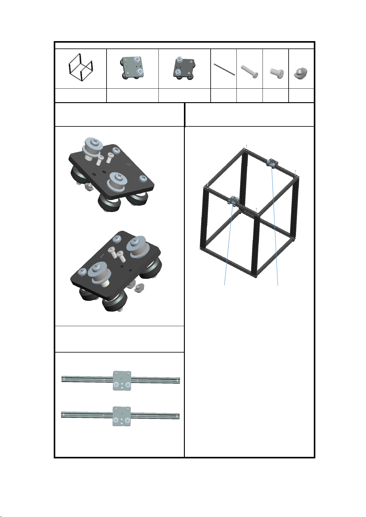
Step 2:Assemble slider plate
Assemble parts specifications and quantity:
Aluminium Frame Slider plate (Left) 1pcs Slider plate (Right) 1pcs
Alu. profile 2
20*20*460mm
2pcs
Screws
PM5*25mm
4pcs
PM4*9mm
screws 4pcs
M4 T nut
4pcs
1, Respectively insert 2pcs PM4*9mm screws to Left and Right slider
plate , lock with M4 T nut , as same as the illustration.
4.Put the aluminum 2 components into the end of the aluminum
frame 3 of the bottom frame, then secured by 4pcs screw PM5*25, as
same as the illustration.
Slider plate(Left) Slider plate(Right)
2. Put 2pcs aluminum 2, through Left and Right slider plat
component respecitve, as same as the illustration.
Note: The wheels are on the side without holes, the slide plate
is on the side with the four holes.
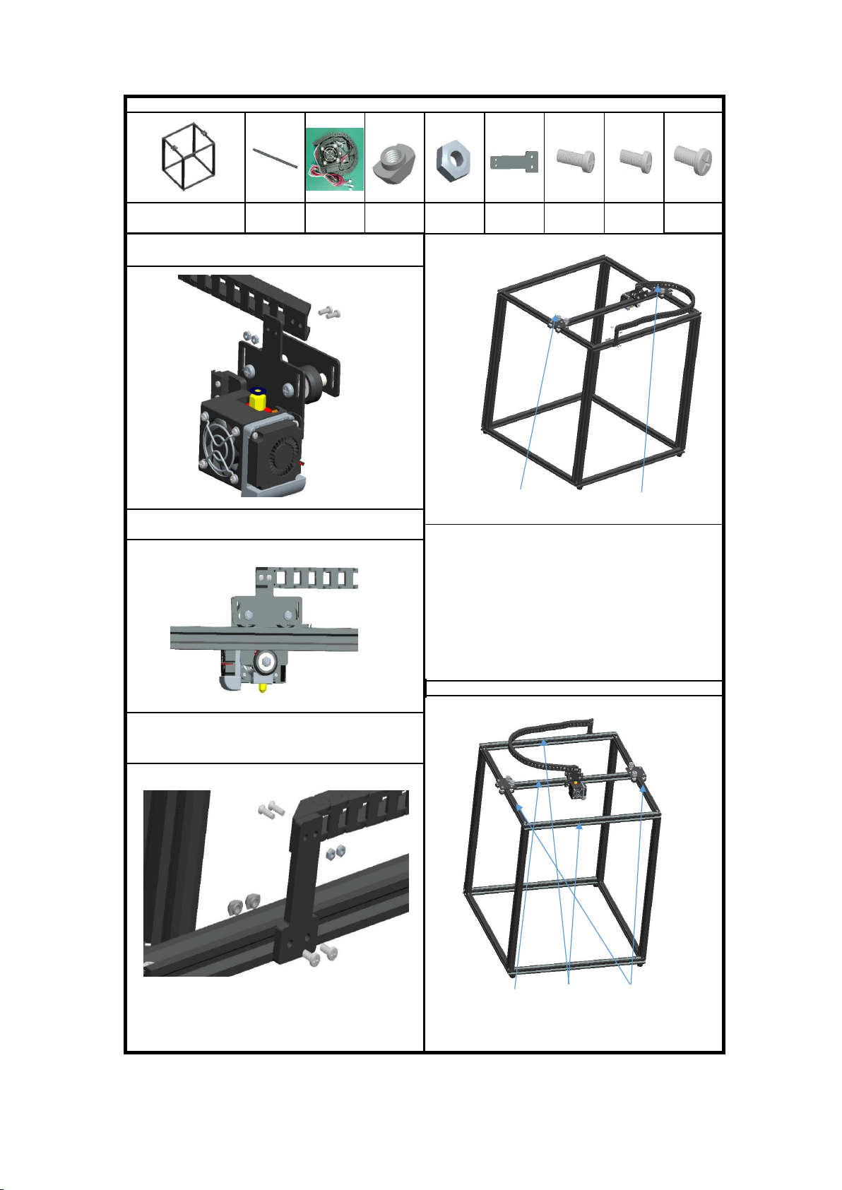
Step 3:Assemble printing head
Assemble parts specifications and quantity:
Aluminium frame
Alu. Profile 4
20*20* 484mm
1pcs
Printing head
component
(with Towline)
1pcs
M4 T-Nut
2pcs
M3 Nut
4pcs
Towline holder
1pcs
PM3*10MM
2pcs
PM3*8MM
2pcs
PM4*9mm
2pcs
1, Place the towline to the printing heat , secure with 2pcs
PM3*8mm screws and M3 Nut
Slider plate(Right) Slider plate(Left)
2.Insert the aluminum profile 4 into the printing head
component,same as the illustration.
3.Put the aluminum 4 component into the T nut of the left and right
slide plate component,screw the screw PM4*9 of the slide plate,same
as the illustration. Move the aluminum profile 4 front and back,make
sure it can move freely,then lock the screw PM4*9, remove the
aluminum 4,ensure it can move freely, lock the screw PM5*25 of the
aluminum 2, move the aluminum 4 again to make sure the movement
is flexible. Lock the screws PM5 * 25 of aluminum profile 2,move the
aluminum 4 again to make sure the movement is flexible, otherwise,
please adjust it again, make sure tthe sliding table is flexible and
without gap shaking after locking the screws
Note:The distance between the aluminum 4 and aluminum 2 is 3mm
3, Assemble the Towline and the holder using 2pcs
PM3*10mm screws and M3 Nuts , then place the towline
holder to the aluminium profile as the illustration.
Alu. Profile
4
Alu.Profile 1 Alu.Profile 2

Step 4:Assemble XY axis motor and wheel
Assemble parts specifications and quantity:
Framework Pulley component
(Right) 1pcs
Pulley component
(Left) 1pcs
Motor 2pcs(With
Synchronous
wheel)
X Motor base
plate 1pcs
Y Motor base
plate 1pcs
M4 T-Nut
10pcs
Screws
PM4*12 10pcs
Screws PM3*10
8pcs
1, Assemble X & Y motor and X & Y motor base plate using 4pcs
PM3*10mm screws , Respectively insert 2pcs PM4*12mm screws to
the plates , lock with M4 T nuts , see the illustration
3.Fix the X motor component,Y motor component,left pulley
component,right pulley component and aluminum by PM4*12mm
screws and M4 T nut, as same as the illustrations.
1, Respectively insert 3pcs PM4*12mm screws to Left and
Right pulley component , lock with M4 T nut , as same as the
illustration.
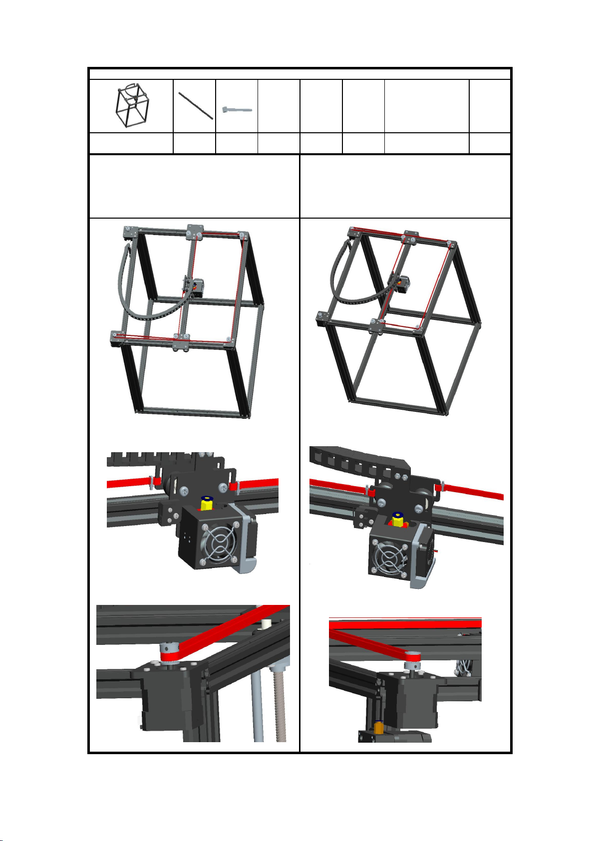
Step 5:Assemble belt
Assemble parts specifications and quantity:
Main frame 1pc Belt 2pcs Tie 4pcs
1.Pass through the belt as same as the illustration ,let the rack is
wrapped with a motor gear, determine direction of the belt, tighten it
to the metal slot of the printing head component with a tie. Adjust the
distance between the X motor gear and the belt,lock 2pcs
jackscrews of the gear.
2.Pass through the belt as same as the illustration,let the rack is
wrapped with a motor gear, determine direction of the belt, tighten the
belt to the metal slot of the print head component with a tie. Adjust
the distance between the Y motor gear and the belt, lock 2pcs
jackscrews of the gear
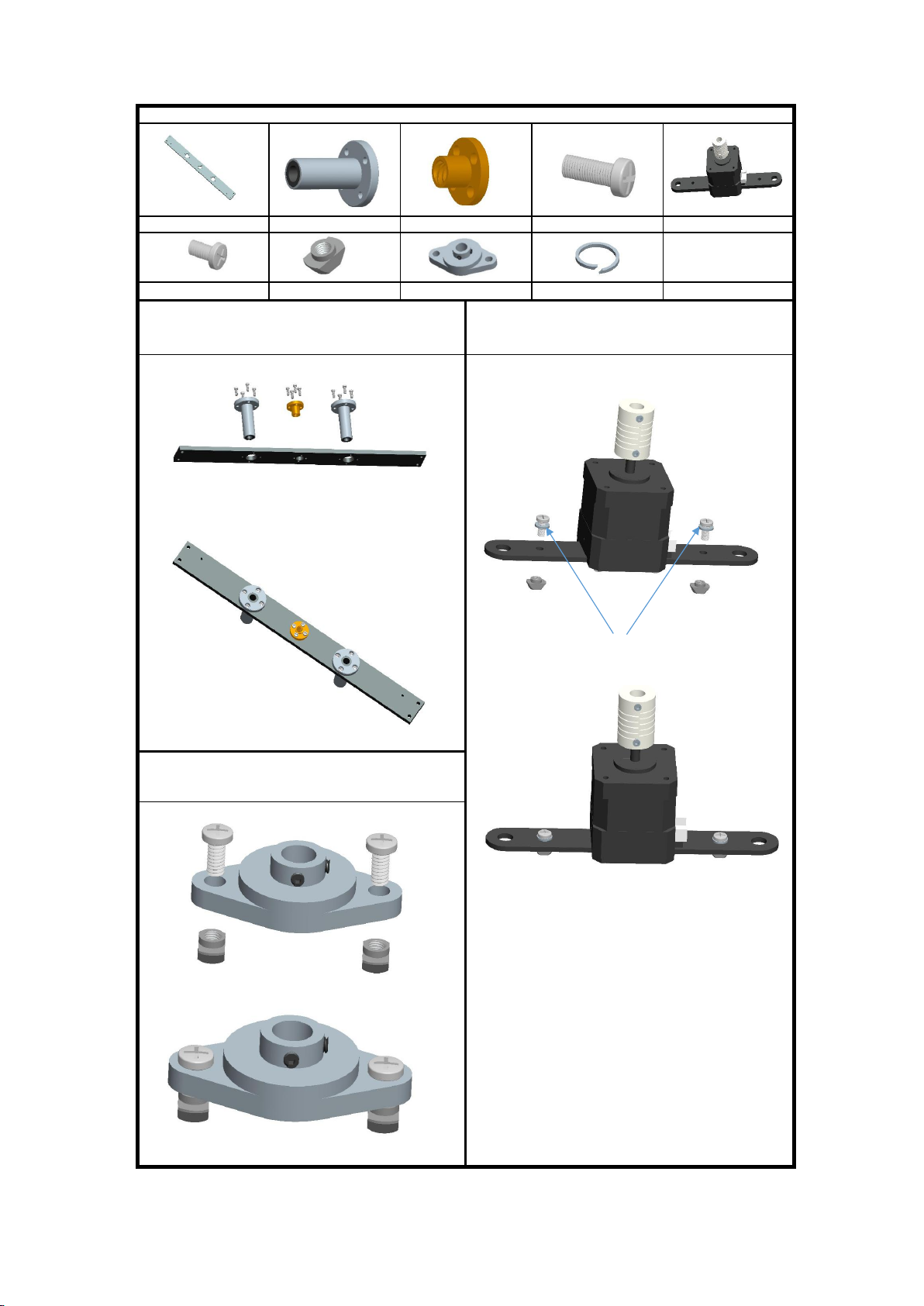
Step 6:Assemble bearings and Z-axis motor
Assemble parts specifications and quantity:
Z fixed plate 2pcs Flange bearing 4pcs Copper Nut 2pcs Screws PM3*8 24pcs Z motor component 2pcs
Screws PM4*9 8pcs M4 T Nut 8pcs Bearing seat 2pcs Elastic gasket 4pcs
1.Assemble 1pc Z fixed plate , 2pcs bearing seat, 1pc screw
nut,12pcs screw PM3*8 together, as the illustration, total need to
assemble 2 set.
3.Assemble 1pc Z motor component,2pcs screw PM4*9mm, 2pcs
Elastic gasket and 2pcs T nut M4 together, total need to assemble 2
set.
Elastic gasket
2.Assemble 1pc bearing seat ,2pcs screw PM4*9mm, 2pcs T nut M4
together,same as the illustration, total need assemble 2set.

Step 7:Assemble Z axis component
Assemble parts specifications and quantity:
Base frame component
1pcs Z motor component 2pcs Z carriage
2pcs
Bearing seat
component
2pcs
Sliding rod
Φ8*528 4pcs
Lead screw
T8*453 2pcs
Screw PM4*20
8pcs
1.Insert the solid end of the Sliding rod to the hole on Z axis motor holder, insert the barrel of
the motor holder into the hole,do not let the pole stand out,same as the illustration.Then,
put the Z fixed plate component with the pole Φ8*528 together. Thread the the lead screws
T8*453 through the copper nut, connect with the coupling hole on the motor,put the bearing
seat component on lead screw T8*453 same as illustration(The T nuts are at the outer
end),then the Z axis carriage is finished. Total need to assemble 2set.
Note:When assemble the pole, keep lead screw T8*453 3mm shorter than sliding rod Φ
8*528mm
2.Adjust the T nut on the Z motor component, Place the Z motors to the
aluminum profile 2 , the 2 small M3 holes stand outsite as the illustration. Align
sliding rod Φ8*528 with the hole of the aluminum profile, let screw PM4 * 20
through the holes of the aluminum profile 2, then connect with the M4 hole of the
sliding rod Φ8*528,same as the illustration, rotate the lead screws T8*453,slide
the carriage and the bearing seat to the top, lock the 2pcs screws PM4*20 to the
aluminum profile 2 ,then lock the M4 T nut and jackscrew of the bearing seat,
rotate the lead screws T8*453, drop the carriage down,make sure it can move
freely. Otherwise, please loosen the jackscrew,adjust it again. then, lock the 4pcs
jackscrew in the coupling , T nut, screw on the Z motor plate, rotate the lead
screw T8*453 again,make sure the Z carriage can slide up and down freely.
finally lock the 2pcs PM4*20 screws from the bottom of the sliding rods .
3.Repeat the number 2,assemble other Z aixs carriage, as the illustration.
Alu. Profile 2
2 small M3 holes stand outside
3mm
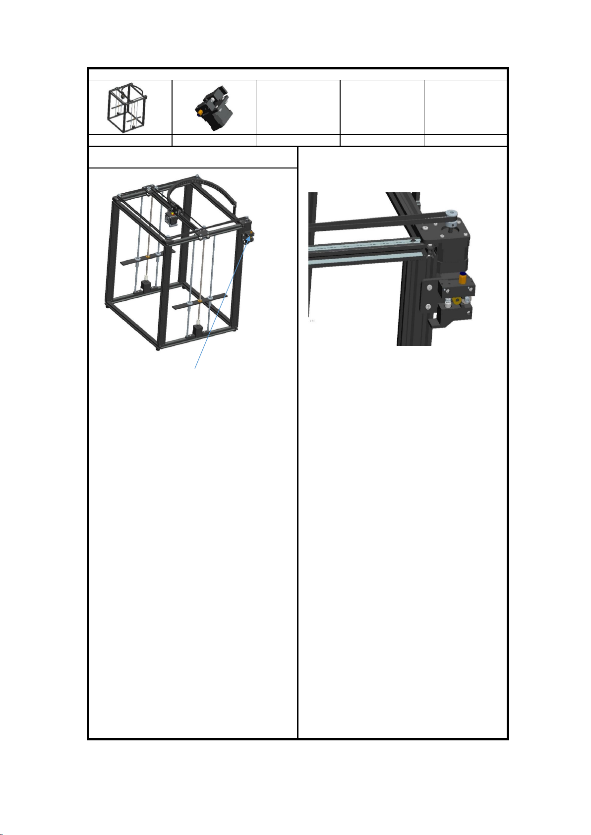
Step 8:Assemble feeding motor
Assemble parts specifications and quantity:
Main framework Feeding motor component 1pcs
1.Place the feeding motor component with 2pcs screw PM4*12 and T
nut M4 ,same as the illustration
Feeding motor component
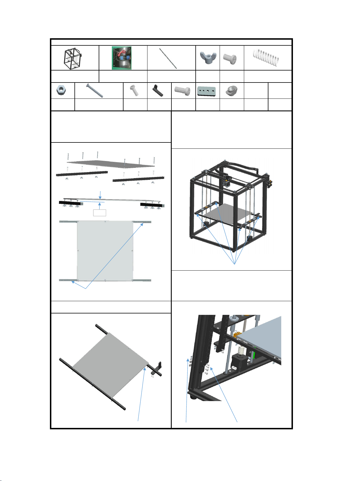
Step 9:Assemble printer plateform
Assemble parts specifications and quantity:
Main framework Heatbed (with towline)
330x330mm 1pcs Metal bar 2pcs M3 Wing
nut 6pcs
PM4*9 screw
2pcs Spring 6pcs
M3 Nut
10pcs KM3*30 screw 6pcs PM4*12
screw 8pcs
Towline
holder 1pcs
PM3*10
screw 6pcs
Towline base
holder 1pcs
M4 T nut
2pcs
1. Put 6pcs KM3 * 30 screws through the heat bed,then lock them
with the nut M3, same as the illustration,put spring through the KM3 *
30 screws,then, extending from the hole of the metal bar,screw into
M3 butterfly nuts, adjust and keep 8 mm between the heat bed and
the metal bar.
3.Rotate 2pcs lead screws T8*453,keep 2 Z carriage at the same
plane, secure the heat bed component and metal bar with 8pcs screw
PM4*12. The towline bracket is close to the side of the feed motor
component, rotate the screw in the same direction,let the platform
move up and down, make sure it can move freely, if not freely, please
lossen the screw PM4*12 to adjust it untill it can move freely
Screws PM4*12
4, Assemble the other end of towline and towline base holder
by using PM3*10mm screws & M3 nut, then secure it to right
side of aluminium profile by using 2pcs PM4*9mm screws,
same as the illustration.
The holes
2. Place the towline holder to the metal bar by using screw
PM3*10, same as the illustration
The heatbed wires exit position M3 Nut PM3*10 screw
8mm
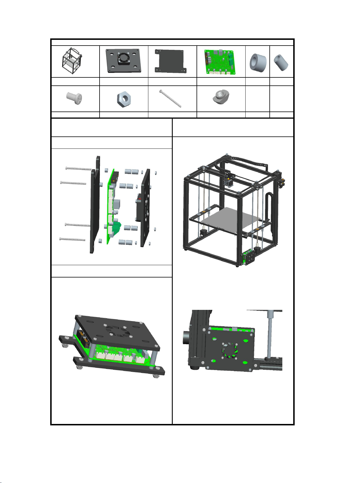
Step 10:Assemble electronic board
Assemble parts specifications and quantity:
Main frame 1pcs Fan Cover 1pcs board holder 1pcs electronic board 1pcs Plastic pillar 1
Φ7*Φ3*4 4pcs
Plastic pillar2
Φ7*Φ4*11 8pcs
Screw PM4*9 3pcs Nut M3 8pcs Screw PM3*45 4pcs T nut M4 3pcs
1.Put the scew PM3*45 through the fan cover, plastic
pillar2,electronic board,Plastic pillar 1,board holder the lock them by
M3 nut, same as the illustration.
3.Fix the electronic board component in the groove of aluminum
profile 2 by T nut, then lock them by screw PM4*9, same as the
illustration.
Note: Please assemble it after wiring . Do not touch the
electronic component by hand for avoiding static electricity.
2.Put 3pcs screw PM4 * 9mm through the board holder,then
lock them with the T nut M4 screw on the boat nut M4
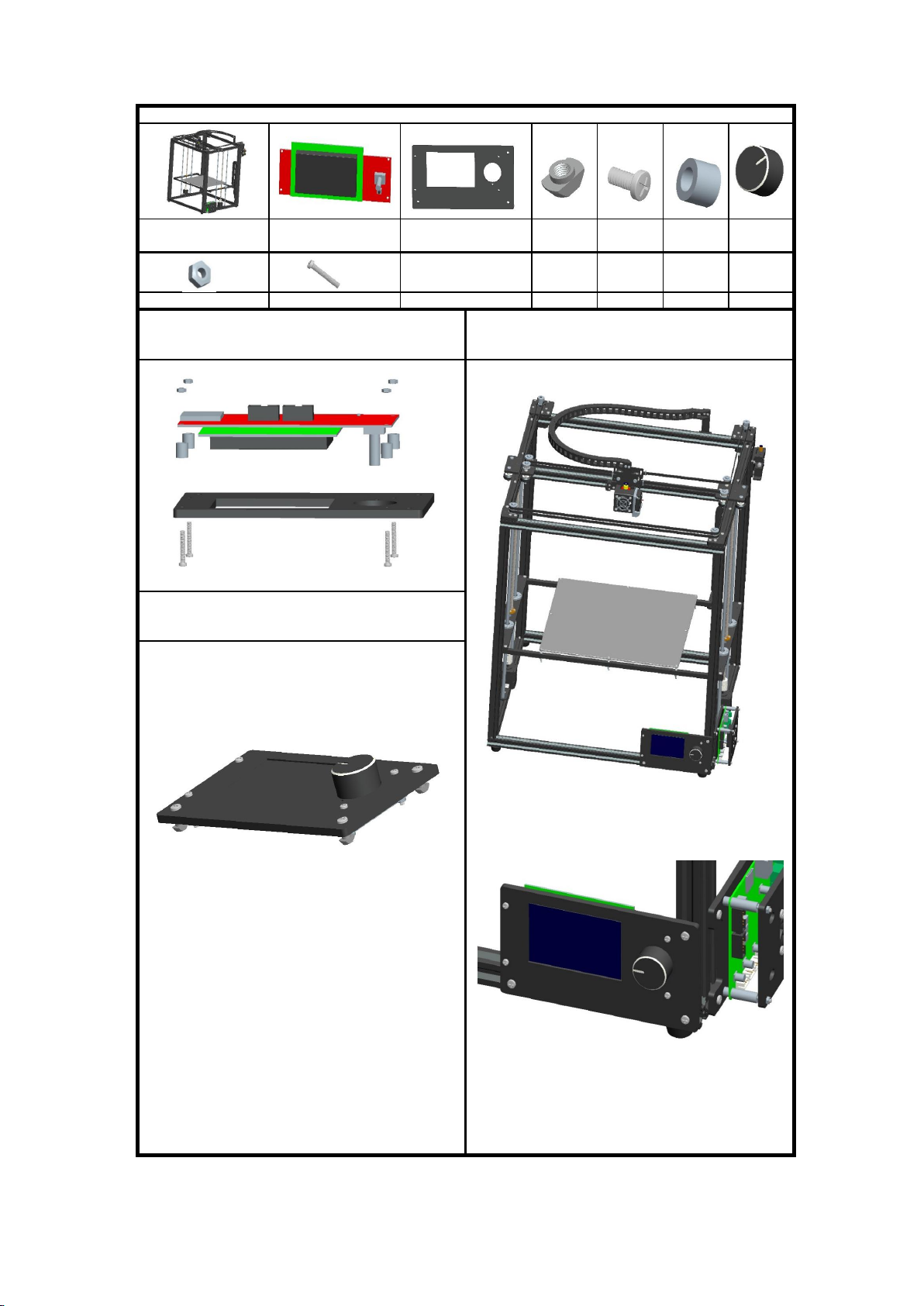
Step 11:Assemble LCD
Assemble parts specifications and quantity:
Main frame 1pcs LCD 1pcs LCD holder 1pcs T nut M4
3pcs
Screw
PM4*9 3pcs
Plastic pillar 3
Φ8*Φ5*8.5 4pcs Knob 1pcs
M3 Nut 4pcs PM3*20 screws 4pcs
1.Put the screw PM3 * 20 through the LCD holder,Plastic
pillar 3, PCB board of the display, then lock them by M3 nut
3. Fix the LCD component in the groove of the aluminum
profile by T nuts,then lock the screw PM4*9, same as the
illustration
2.Put 3pcs screw PM4*9 through LCD holder, then, lock by
nut M4,then insert the knob, same as the illustration
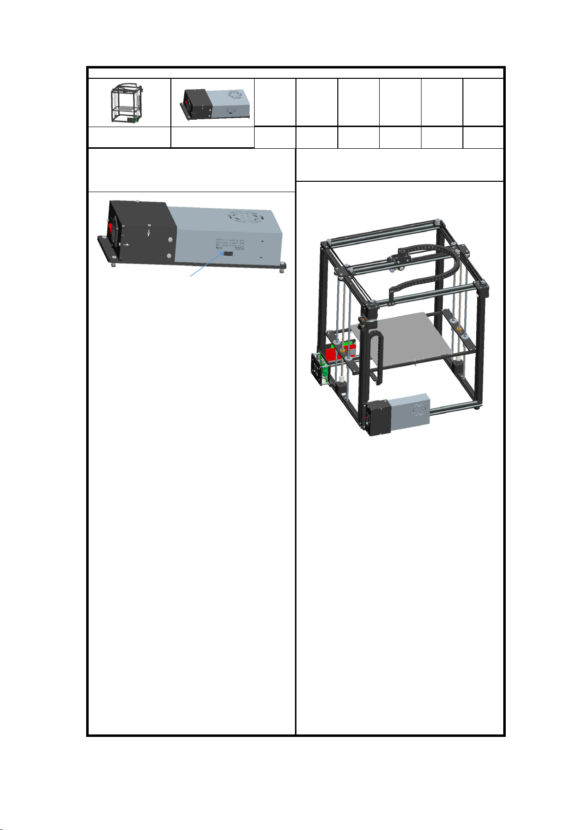
Step 12:Assemble power supply
Assemble parts specifications and quantity:
Main frame 1pcs Power supply 30A 1pcs
1, Take the power supply , select the correct voltage by using
screwdriver, same as illustration.
2.Fix the power supply component in the groove of aluminum
profile by 3pcs screw PM4*9 and T nut, same as illustration
110/220 Voltage switch
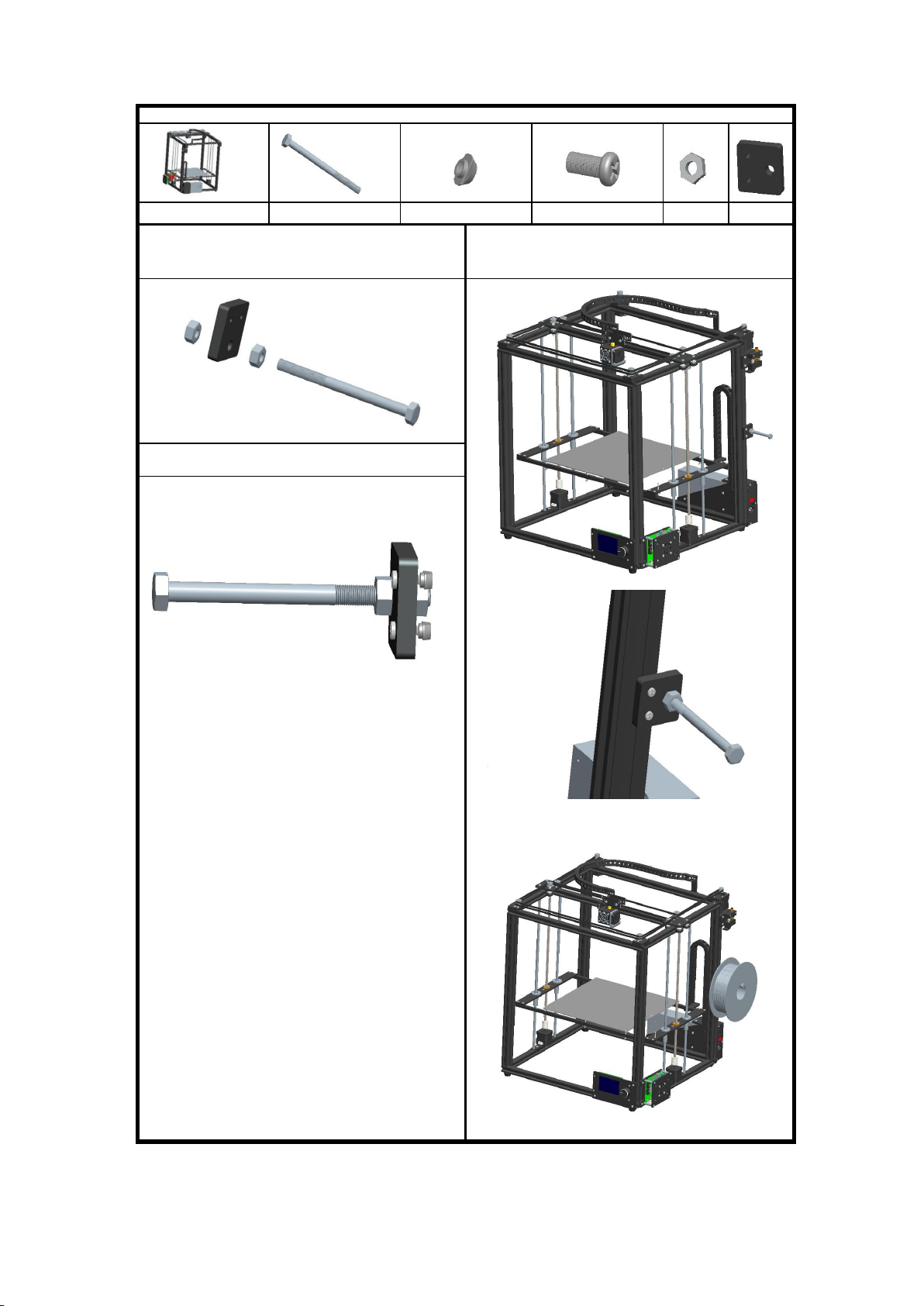
Step 13:Assemble feeding holder
Assemble parts specifications and quantity:
Main framework Hexagon Screw M8*110 1pcs T nut M4 2pcs Screw PM4*12 2pcs Nut M8 2pcs Feeding holder
Plate 1pcs
1.Assemble 1pc Feeding holder plate with 1pc Hexagon
Screw,2pcs nut M8 together, same as the illustration
3.Fix feeding holder component in the groove of aluminum profile by
2pcs screw PM4*12,same as the sillustration (Put the material tray
hang onto the rod of the screw)
2.Put 2pcs screw PM4*12 through the feeding holder plate
,then lock with T nut M4.
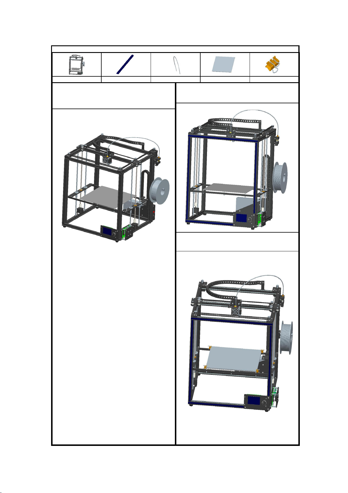
Step 14:Assemble Decorative strip and Feeding tube
Assemble parts specifications and quantity:
Main framework Aluminium profile seal Feeding tube 1pcs Print board 1pcs Binder Clip 4pcs
1.Put the feeding tube into the hole of the Air cock,insert feeding
tube,press the outer plastic ring of Air cock,loosen the plastic
ring,stuck the feeding tube,same as illustration,move the feeding
tube up and down to make sure it is clenched
2.Align the end seal with the end aluminum profile,then press the seal
into the groove of the aluminum profile,same as illustration.
3, Place the print board on the heatbed , tighten it by using
4pcs Binder Clip
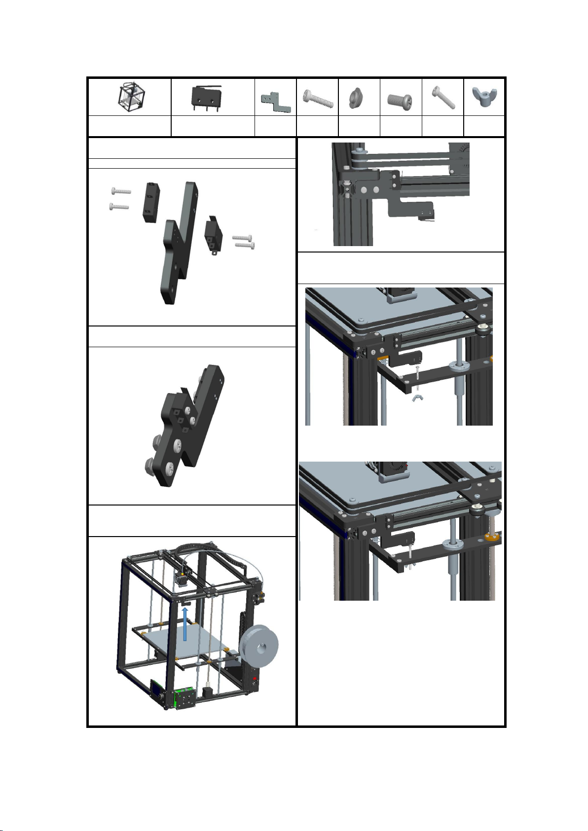
Step 15:Assemble limit switch
Assemble parts specifications and quantity:
Main framework Limit switch (with wires)
2pcs
Switch holder
1pcs
Screw PA2*10
4pcs
M4 T Nut
2pcs
PM4*9
screws 2pcs
PM3*35
screws
1pcs
M3 Wing Nut
1pcs
1, Assemble the limit switchs to the holder by using 2pcs
PA2*10 Screws , secure them .
Note: Must be careful when making screws.
4, Take 1pcs PM3*35mm screws , through the Z carriage as
illustration, adjust it to the fit height , secure it by using M3
wing nut from the bottom.
2. Put 2pcs screw PM4*9 through switch component, then
lock with T nut M4, same as illustration
3.Fix switch component in the groove of aluminum profile with
2pcs T nut, then lock 2pcs screw PM4*9,same as the
illustration

Step 16:Connecting wire
Assemble parts specifications and quantity:
Main framework Power wires 2pcs USB cable 1pcs LCD cable 2pcs Motor wires 4P*5pcs
Winding Pipe 1pcs Power plug 1pcs
Mainboard and LCD wiring diagram Printer wiring parts schematic
1, Open the cover of the electronic board.
2.Connect the terminal of the electronic board and the LCD
with the LCD cable 1,LCD cable 2,same as above illustration,
3.Plug the motor wire to the terminal of the electronic board,
same as above illustration
4.Plug the switch wire of the X,Y,Z to the terminal of the
electronic board,same as above illustration
5.Connect the heatbed and the thermistor to the mainboard
terminal , there are no '+' and '-' different of the heatbed.
6.Insert the wire terminals of the printing head fan into the
terminal of 4010 Fan-1, 4010 Fan-2 on the electronic board .
Plug the terminal of the printing head heading plate to the
terminal of the Extr.Thermistor, then lock the soaked tin wire
of the heating plate and Extruder terminal of the electronic
board.
Heatbed 4P wires
7, Connect the 2pcs power wires to the mainboard , the red to '+', the black to '_'
8, Different countrys are different voltage, select 110V or
220V.
9, Connect the fan on the cover to the mainboard, the red to '+', the black to '-'.
10.Plug the power supply cable,adjust the printer,make sure it
can run,wrap the wire with the pipe .Finally, close the cover.
Extruder 10P wires
Z-motor 1
Z-motor 2
Y-Motor
X-Motor
Extr.motor
Y Endstop
Z Endstop
X Endstop
4010 Fan 2
4010 Fan 1
Heat
Extruder
Other TRONXY 3D Printer manuals

TRONXY
TRONXY X3A User manual

TRONXY
TRONXY X5SA-500-2E User manual

TRONXY
TRONXY X1 User manual

TRONXY
TRONXY XY-2 User manual

TRONXY
TRONXY VEHO 600-2E User manual

TRONXY
TRONXY X5SA-400-2E User manual

TRONXY
TRONXY XY-3 PRO V2 User manual

TRONXY
TRONXY X6D User manual

TRONXY
TRONXY XY-2 PRO User manual

TRONXY
TRONXY Ultrabot User manual

TRONXY
TRONXY X5SA-500-PRO User manual

TRONXY
TRONXY X3A User manual

TRONXY
TRONXY XY-3 User manual

TRONXY
TRONXY XY-2 PRO User manual

TRONXY
TRONXY X6-2E User manual

TRONXY
TRONXY P802M User manual

TRONXY
TRONXY X5 User manual

TRONXY
TRONXY X3A User manual

TRONXY
TRONXY D01 User manual

TRONXY
TRONXY X5SA-400-PRO User manual


