ST SPC572LADPT100S User manual

Introduction
The SPC572LADPT100S mini module is an evaluation board supporting STMicroelectronics SPC572L64E3 device in
LQFP100-EP package.
Figure 1. SPC572LADPT100S
Note: picture not contractual.
SPC572LADPT100S evaluation board
UM3063
User manual
UM3063 - Rev 1 - August 2022
For further information contact your local STMicroelectronics sales office.
www.st.com

1Overview
The SPC572LADPT100S mini module is an evaluation board supporting the STMicroelectronics SPC572L64E3
device in LQFP100-EP package.
The SPC572LADPT100S mini module can be connected onto the SPC58XXMB motherboard. It offers a
mechanism for easy customer evaluation of the SPC572Lxx family of device and to facilitate hardware and
software development. High density connectors provide the interface between the EVB and MCU daughter cards
and help the developers evaluate all device peripherals.
This user manual provides information on using the SPC572LADPT100S mini module board and its hardware
features.
The mini module may be used as a standalone unit allows access to the CPU, but no access to the I/O pins as
any motherboard peripherals.
Figure 2. Overview of SPC572LADPT100S mini module - top
UM3063
Overview
UM3063 - Rev 1 page 2/29

Figure 3. Overview of SPC572LADPT100S mini module - bottom
1.1 Supported devices
The SPC572LADPT100S evaluation board supports the following STMicroelectronics family of microcontrollers in
LQFP100-EP:
• SPC572L64E3
UM3063
Supported devices
UM3063 - Rev 1 page 3/29

2License agreement
The packaging of this evaluation board was sealed with a seal stating, by breaking this seal, you agree to the
terms and conditions of the evaluation board license agreement, the terms and conditions of which are available
at https://www.st.com/resource/en/evaluation_board_terms_of_use/evaluationproductlicenseagreement.pdf.
Upon breaking the seal, you and STMicroelectronics entered into the evaluation board license agreement, a copy
of which is also enclosed with the evaluation board for convenience.
Attention: This evaluation board only offers limited features for evaluating ST products. It has not been tested for use
with other products and is not suitable for any safety or other commercial or consumer application. This
evaluation board is otherwise provided “AS IS” and STMicroelectronics disclaims all warranties, express or
implied, including the implied warranties of merchantability and fitness for a particular purpose.
UM3063
License agreement
UM3063 - Rev 1 page 4/29

3Handling precautions
Please take care to handle the package content in order to prevent electrostatic discharge.
Before the EVB is used or the power is applied, please fully read the following sections on how to correctly
configure the board. Failure to correctly configure the board may cause irreparable component, MCU or EVB
damage.
UM3063
Handling precautions
UM3063 - Rev 1 page 5/29

4Hardware description
4.1 Hardware features
The SPC572LADPT100S mini module board has the following features:
• Can be used as a stand-alone board by providing external power supplies input (5 V, 3.3 V, 1.25 V)
• Reset button with driver and led indicator
• SPC572LADPT100S has socket for device in LQFP100-EP package
• Debug ports:
– 34-pin SAMTEC connector for Nexus 2
– 14-pin header connector for JTAG port
– 12-pin header connector for SIPI interface
• 40 MHz crystal main oscillator with jumpers to optionally disconnect it
• 8 MHz oscillator with jumpers to optionally disconnect it
• Clock input through SMA connector to optionally disconnection
• 2 X SAMTEC QSH series, 240 way connector to connect mini module to motherboard
4.2 Hardware dimensions
The evaluation board has the following dimensions:
• PCB area: 127 mm x 114.3 mm
• Top components height: 18.8 mm
• Bottom components height: 3.5 mm
• PCB thickness 1.6 mm
4.3 Pin numbering for jumpers
3-pin jumpers for the mini module have rectangular pad to indicate the position of pin 1 and there is the PCB
silk-screen with the numbers of all the pins. See the example below for the numbering convention used in this
manual for jumpers settings:
Figure 4. Overview of 3-pin jumpers numbering convention
6-pin jumpers for the mini module have the PCB serigraphy with the numbers of all pins. See the example below
for the numbering convention used in this manual for jumpers settings:
Figure 5. Overview of 6-pin jumpers numbering convention
UM3063
Hardware description
UM3063 - Rev 1 page 6/29

5Power and system configuration
5.1 Power supplies
When the mini module is plugged onto the motherboard, power is supplied directly by the motherboard. In this
setup, the external power supply input available on the mini module should NOT be used.
When the SPC572LADPT100S mini module is used as a stand-alone board external power supplies must be
used (5 V, 3.3 V, 1.25 V).
The following jumpers are used to configure the power supply:
Table 1. Power supplies configuration jumpers
Jumper Description Default Position
J1
VDD_HV_ADV voltage configuration:
• 1-2: 5V_LR (linear)
• 2-3: 5V_SW (switching)
1-2 (5V_LR) B2(1)
J3
VDD_HV_ADR voltage configuration:
• 1-2: 5V_LR (linear)
• 2-3: 5V_SW (switching)
1-2 (5V_LR) B2(1)
J5
VDD_HV_IO_JTAG/VDD_HV_OSC0 voltage configuration:
• 1-2: 5V_SR
• 2-3: 3.3V_SR
1-2 (5V_SR) B2(1)
J6
VDD_HV_IO_MAIN voltage configuration:
• 1-2: 5V_SR
• 2-3: 3.3V_SR
1-2 (5V_SR) B2(1)
J7
VDD_HV_IO_ETH voltage configuration:
• 1-2: 5V_SR
• 2-3: 3.3V_SR
1-2 (5V_SR) B2(1)
J8
VDD_LV1 configuration for external 1.25 V use:
• Open: VDD_LV1 not connected to 1.25 V
• Closed: VDD_LV1 connected to 1.25 V
Open C2(1)
J25
VDD_LV2 configuration for external 1.25V use:
• Open: VDD_LV2 not connected to 1.25 V
• Closed: VDD_LV2 connected to 1.25 V
Open B2(1)
J26
VDD_LV3 configuration for external 1.25 V use:
• Open: VDD_LV3 not connected to 1.25 V
• Closed: VDD_LV3 connected to 1.25 V
Open B2(1)
1. Refer to the Figure 10. SPC572LADPT100S mini module - top.
UM3063
Power and system configuration
UM3063 - Rev 1 page 7/29

5.2 Port configuration
The following jumpers need to configure the ports:
Table 2. Ports related jumpers
Jumper Description Default Position
J9
PD[6] connection to QSH connectors configuration:
• Open: PD[6] not connected to QSH connectors (motherboard)
• Closed: PD[6] connected to QSH connectors (motherboard)
Closed C2(1)
J10
PD[6] c connection to EVTI configuration:
• Open: PD[6] not connected to EVTI
• Closed: PD[6] connected to EVTI
Open C2(1)
J11
TESTMODE connection configuration:
• Open: TESTMODE not connected
• Closed: TESTMODE connected to:
– R6 mounted: pulldown (default)
– R3 mounted: pullup
Closed (default pull-down) A2(1)
J27
PD[6] connection to EVTO configuration:
• Open: PD[6] not connected to EVTO
• Closed: PD[6] connected to EVTO
Open C2(1)
JP1
PD[6] connection to VDD_LV3
• Open: PD[6] not connected to VDD_LV3
• Closed: PD[6] connected to VDD_LV3
Open C2(2)
JP2
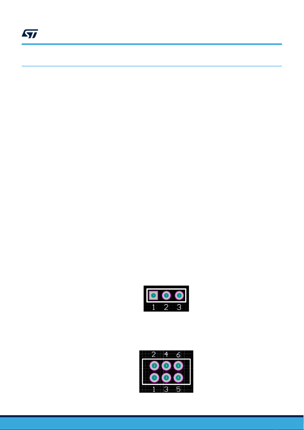
PA[6] connection configuration:
• 1-2: PA[6] connected to TCK
• 2-3: PA[6] connected to DRCLK
1-2 (TCK) B2(1)
JP3
PA[9] connection to QSH connectors configuration:
• Open: PA[9] not connected to QSH connectors (motherboard)
• Closed: PA[9] connected to QSH
Open A3(1)
JP4
PA[2] connection configuration
• 1-2: PA[2] connected to QSH
• 2-3: PA[2] connected to VDD_HV_IO_MAIN
1-2 A2(1)
JP5
PA[8] connection configuration:
• 1-2: PA[8] connected to TDI
• 2-3: PA[8] connected to SIPI_TXP
1-2 (TDI) B2(1)
JP7
PF[13] connection to QSH connectors configuration:
• Open: PF[13] not connected to QSH connectors (motherboard)
• Closed: PF[13] connected to QSH
Closed B2(1)
JP8
PD[6] c connection to SIPI_TXN configuration:
• Open: PD[6] not connected to SIPI_TXN
• Closed: PD[6] connected to SIPI_TXN
Open B2(1)
JP9
PD[7] connection to QSH connectors configuration:
• Open: PD[7] not connected to QSH connectors (motherboard)
• Closed: PD[7] connected to QSH
Closed B2(1)
JP10
PA[6] connection to QSH connectors configuration:
• Open: PA[6] not connected to QSH connectors (motherboard)
• Closed: PA[6] connected to QSH
Open B2(1)
JP11 PA[7] connection to QSH connectors configuration:
• Open: PA[7] not connected to QSH connectors (motherboard) Open B2(1)
UM3063
Port configuration
UM3063 - Rev 1 page 8/29

Jumper Description Default Position
• Closed: PA[7] connected to QSH
JP12
PA[8] connection to QSH connectors configuration:
• Open: PA[8] not connected to QSH connectors (motherboard)
• Closed: PA[8] connected to QSH
Open B2(1)
1. Refer to the Figure 10. SPC572LADPT100S mini module - top
2. Refer to the Figure 11. SPC572LADPT100S mini module - bottom
5.3 System clock configuration
The mini module supports the usage of crystal clock sources as well as external clock source:
Table 3. System clock related jumpers
Jumper Description Default Position
J13
EXTAL connection configuration:
• 1-2: EXTAL connected to 40 MHz crystal clock source
• 2-3: EXTAL connected to EXTAL EVB clock source
1-2 (XT1 pin2) C3(1)
J15
XTAL connection configuration:
• 1-2: XTAL connected to 40 MHz crystal clock source
• 2-3: XTAL connected to XTAL EVB clock source
1-2 (XT1 pin1) C3(1)
J17
8 MHz oscillator enable jumper:
• Open: 8 MHz oscillator not enabled
• Closed: 8 MHz oscillator enabled
Open D3(1)
J19
Jumper selector of external clock source:
• 1-2: from 8 MHz oscillator
• 2-3: from SMA connector
1-2 C3(1)
1. Refer to the Figure 10. SPC572LADPT100S mini module - top
UM3063
System clock configuration
UM3063 - Rev 1 page 9/29

5.4 Reset circuit configuration
The mini module supports different ways to reset the devices. To use and perform the reset driving there are
different jumpers and switches:
Table 4. Reset configuration jumpers
Jumper Description Default Position
SW1 Reset push button Open D1(1)
J18
External reset connection to the ESR0 pin configuration:
• Open: the external reset is not connected to the ESRO pin
• Closed: the external reset is connected to the ESRO pin
Closed D1(1)
J20
External reset connection used to reset driver configuration:
• Open: the external reset is not connected to the reset driver for ESRO and PORST pins
• Closed: the external reset is connected to the reset driver for ESRO and PORST pins
Closed D1(1)
J21
External reset connection to PORST pin configuration:
• Open: the external reset is not connected to the PORST pin
• Closed: the external reset is connected to the PORST pin
Closed D2(1)
1. Refer to the Figure 10. SPC572LADPT100S mini module - top
5.5 Connectors
The mini module has other connectors described in the table below:
Table 5. Connectors
Connectors Description Position
J12 14-pin header connector for JTAG port A1(1)
J14 34-pin SAMTEC connector for nexus 2 A2(1)
J16 10-pin SIPI interface connector C2(1)
J2 External power supplies input D4(1)
J23 2 X SAMTEC QSH series, 240 way connector to
connect minimodule to motherboard
A4 ... D4(2)
J24 A1 ... D1(2)
1. Refer to the Figure 10. SPC572LADPT100S mini module - top
2. Refer to the Figure 11. SPC572LADPT100S mini module - bottom
UM3063
Reset circuit configuration
UM3063 - Rev 1 page 10/29

The following figure shows the JTAG connector scheme:
Figure 6. JTAG connector scheme
EVTI
ESR0
PORST
EVTO
VDD_HV_IO_JTAG/VDD_HV_OSC
ESR0
TDI
TDO
TCK
TRST
PORST
TMS
EVTI
EVTO
GND GND
GND
NOT MOUNTED
NOT MOUNTED
NOT MOUNTED
GND
1 2
3 4
5 6
7 8
9 10
11 12
13 14
N2514-6002RB
J12
10K
1/10W
0603
R8
10K DNP
1/10W
0603
R14
0R DNP
1/10W
0603
R7
0603
27pF
50V
COG/NP0
C35
0603
47pF DNP
50V
COG/NP0
C34
The following table shows the JTAG connector pinout:
Table 6. JTAG Header 2x7 pins connector pinout
Pin number Signal
1 TDI
2 GND
3 TDO
4 GND
5 TCK
6 GND
7 EVTI
8 PORST
9 ESR0
10 TMS
11 VDD_HV_IO_MAIN
12 GND
13 EVTO
14 N.C.
UM3063
Connectors
UM3063 - Rev 1 page 11/29

The following picture shows the NEXUS SAMTEC ASP-137973-01 connector schema:
Figure 7. NEXUS SAMTEC ASP-137973-01
PORST
ESR0
3.3V_SR
ESR0
TDI
TCK
PORST
TMS
TDO
TRST
EVTI
GND GND
EVTO
EVTO
EVTI
GND
NOT MOUNTED
TX0P
1
TX0N
3
gnd
5
TX1P
7
TX1N
9
gnd
11
TX2P
13
TX2N
15
+V 2
TCK 4
TMS 6
TDI 8
TDO 10
JCOMP 12
EVTI1 14
EVTI0 16
EVTO0 18
PORST 20
ESR0 22
gnd 24
CLKP 26
CLKN 28
gnd 30
TX3P
19
gnd
23
gnd
29
n.c.
25
gnd
17
n.c.
27
TX3N
21
n.c.
31 EVTO1 32
n.c.
33 n.c. 34
SH1
SH1 SH2 SH2
SAMTEC ASP-137973-01
J14
0603
47pF DNP
50V
COG/NP0
C38
Table 7. NEXUS SAMTEC ASP-137973-01 connector pinout
Pin number Signal
1 N.C.
2 3.3 V
3 N.C.
4 TCK
5 GND
6 TMS
7 TX1P
8 TDI
9 TX1N
10 TDO
11 GND
12 JCOMP
13 N.C.
14 N.C.
15 N.C.
16 EVTI
17 GND
18 EVTO
19 N.C.
UM3063
Connectors
UM3063 - Rev 1 page 12/29

Pin number Signal
20 PORST
21 N.C.
22 ESR0
23 GND
24 GND
25 N.C.
26 N.C.
27 N.C.
28 N.C.
29 GND
30 GND
31 N.C.
32 N.C.
33 N.C.
34 N.C.
SH1 GND
SH2 GND
The following figure shows the SIPI interface scheme:
Figure 8. SIPI interface scheme
SIPI_TXP
SIPI_TXN
SIPI_RXN
SIPI_RXP
SIPI_RXP
SIPI_RXN
SIPI_TXP
SIPI_TXN
GND GND
1 2
3 4
65
7 8
9 10
SH1 SH2
ERF8-005-05.0-L-DV-L-TR
J16
DRCLK DRCLK
UM3063
Connectors
UM3063 - Rev 1 page 13/29

The following picture shows the SIPI interface connector pinout:
Table 8. SIPI interface connector pinout
Pin number Signal
1 SIPI_TXP
2 GND
3 SIPI_TXN
4 GND
5 GND
6 DRCLK
7 SIPI_RXN
8 GND
9 SIPI_RXP
10 GND
The following figure shows the external power supply connector scheme:
Figure 9. External power supply connector scheme
5.0V_SR3.3V_SR1.25V_SR
GND
1
2
3
4
1437671-6
J2
Table 9. External power supply connector pinout
Pin number Signal
1 1.25 V
2 3.3 V
3 5 V
4 GND
UM3063
Connectors
UM3063 - Rev 1 page 14/29

5.6 Test points
Several test points of different shape and functionality are scattered around the SPC572LADPT100S evaluation
board to allow easy access to MCU and reference signals. This chapter summarizes and describes the available
test points. Test points are listed and detailed in the following table.
Table 10. Test points
Test point Description Position
GT1 GND test point A3(1)
GT2 GND test point D3(1)
GT3 GND test point C2(1)
GT4 GND test point A1(1)
GT5 GND test point D1(1)
TP1 AGND test point C3(1)
TP2 TRST test point (JTAG) A1(1)
TP3 TCK test point (JTAG) A1(1)
TP4 TMS test point (JTAG) A1(1)
TP5 TDI test point (JTAG) A1(1)
TP6 TDO test point (JTAG) A1(1)
TP7 SIPI_TXN test point C2(1)
TP8 SIPI_TXP test point C2(1)
TP9 SIPI_RXN test point C2(1)
TP10 SIPI_RXP test point C2(1)
TP11 J23A, QSH connector, pin10 (PA[5]) test point A4(1)
TP16 J23A, QSH connector, pin19 (PA[14]) test point A4(1)
TP17 J24B, QSH connector, pin210 (PD[6]) test point C1(1)
TP18 J24B, QSH connector, pin209 (PD[7]) test point D1(1)
TP19 J24B, QSH connector, pin183 (PF[13]) test point C1(1)
1. Refer to the Figure 10. SPC572LADPT100S mini module - top
UM3063
Test points
UM3063 - Rev 1 page 15/29

6Layout overview
Figure 10. SPC572LADPT100S mini module - top
1
2
3
4
ABCD
UM3063
Layout overview
UM3063 - Rev 1 page 16/29

Figure 11. SPC572LADPT100S mini module - bottom
1
2
3
4
ABCD
UM3063
Layout overview
UM3063 - Rev 1 page 17/29

7BOM
Table 11. BOM
Item Qty Reference Value Option Layer Pins Footprint
DUT1 1 LAVAREDO-LQFP100EP Top 103 100LQFP_EP(20X20)WELLS_3014_100_X_0E
GT1, GT2, GT3, GT4, GT5, TP1 6 TEST2 Top 1 TEST2
J1, J3, J5, J6, J7, J13, J15, J19 8 STRIP3PM Top 3 SIP-3P
J2 1 TYCO-1437671-6 Top 4 TYCO-1437671-6
J8, J9, J10, J11, J17, J18, J20, J21, J25,
J26, J27 11 STRIP2PM Top 2 SIP-2P
J12 1 M.14.180 LP-3M Top 14 N2514-6002RB
J14 1 SAM-ASP13797301 Top 38 ASP-137973-01
J16 1 CONNERF805X2-SMD Top 14 ERF8-005-05.0-X-DV-L
J22 1 BNC-SMA-FEM-180 Top 2 SMA-PASTERNACK-PE4117
JP2, JP4, JP5, JP6 4 JUMPER Top 3 JUMPER_SMD_3VIA_SMALL
LD1, LD2 2 LEDSMDGIAL-0805, LEDSMDRED-0805 Top 2 LED_SMD_0805
OSC1 1 Q8MHZ-SMD-3953M 8 MHz Top 4 QUARZO-SMD-ECS-3953
SW1 1 PULSANTER Top 4 PUSH_BUTTON
TP2, TP3, TP4, TP5, TP6, TP7, TP8,
TP9, TP10, TP11, TP16, TP17, TP18,
TP19
14 TEST2 Top 1 CHIRI-SMD
U1 1 74_125 Top 14 SO14NB
U3 1 74V1G08-SMD Top 5 SOT-23-5LEAD
XT1 1 Q40MHZ-SMD-5032 40 MHz Top 2 QUARZO-SMD-NX5032GA
JP1, JP3, JP7, JP8, JP9, JP10, JP11,
JP12 8 JUMPER Bottom/Top 2 JUMPER
J23, J24 2 SAM-QSH12001LDA Bottom 258 QSH-120-01-X-D-A
R1 1 RESMD49R9-805 49R9 Bottom 2 RES-0805-SMALL
R2 1 RESMD000-0603 0R Bottom 2 RES-0603-SMALL
R3 1 RESMD103-0603 10K DNP Top 2 RES-0603-SMALL
R4 1 RESMD472-0603 4K7 Bottom 2 RES-0603-SMALL
R5 1 RESMD472-0603 4K7 Bottom 2 RES-0603-SMALL
R6 1 RESMD103-0603 10K Top 2 RES-0603-SMALL
UM3063 - Rev 1 page 18/29
UM3063
BOM

Item Qty Reference Value Option Layer Pins Footprint
R7 1 RESMD000-0603 0R DNP DNP Top 2 RES-0603-SMALL
R8 1 RESMD103-0603 10K Top 2 RES-0603-SMALL
R14 1 RESMD103-0603 10K DNP Top 2 RES-0603-SMALL
R15 1 RESMD000-0603 0R Top 2 RES-0603-SMALL
R21 1 RESMD561-0603 560R Top 2 RES-0603-SMALL
R22 1 RESMD561-0603 560R Top 2 RES-0603-SMALL
R23 1 RESMD103-0603 10K Top 2 RES-0603-SMALL
R24 1 RESMD221-0603 220R Top 2 RES-0603-SMALL
R25 1 RESMD472-0603 4K7 Top 2 RES-0603-SMALL
R26 1 RESMD221-0603 220R Top 2 RES-0603-SMALL
R27 1 RESMD101-0603 100R Top 2 RES-0603-SMALL
C1 1 CCERSMD225-0805M 2.2uF Bottom 2 CAP-0805-SMALL
C2 1 CCERSMD104-0603M 100nF Bottom 2 CAP-0603-SMALL
C3 1 CCERSMD102-0603V 1nF Bottom 2 CAP-0603-SMALL
C4 1 CCERSMD475-0805M 4.7uF Bottom 2 CAP-0805-SMALL
C5 1 CCERSMD104-0603M 100nF Bottom 2 CAP-0603-SMALL
C6 1 CCERSMD102-0603V 1nF Bottom 2 CAP-0603-SMALL
C7 1 CCERSMD475-0805M 4.7uF Bottom 2 CAP-0805-SMALL
C8 1 CCERSMD104-0603M 100nF Bottom 2 CAP-0603-SMALL
C9 1 CCERSMD102-0603V 1nF Bottom 2 CAP-0603-SMALL
C10 1 CCERSMD104-0603M 100nF Bottom 2 CAP-0603-SMALL
C11 1 CCERSMD102-0603V 1nF Bottom 2 CAP-0603-SMALL
C12 1 CCERSMD475-0805M 4.7uF Bottom 2 CAP-0805-SMALL
C13 1 CCERSMD104-0603M 100nF Bottom 2 CAP-0603-SMALL
C14 1 CCERSMD102-0603V 1nF Bottom 2 CAP-0603-SMALL
C15 1 CCERSMD475-0805M 4.7uF Bottom 2 CAP-0805-SMALL
C16 1 CCERSMD104-0603M 100nF Bottom 2 CAP-0603-SMALL
C17 1 CCERSMD102-0603V 1nF Bottom 2 CAP-0603-SMALL
C18 1 CCERSMD475-0805M 4.7uF Bottom 2 CAP-0805-SMALL
C19 1 CCERSMD104-0603M 100nF Bottom 2 CAP-0603-SMALL
C20 1 CCERSMD102-0603V 1nF Bottom 2 CAP-0603-SMALL
UM3063 - Rev 1 page 19/29
UM3063
BOM

Item Qty Reference Value Option Layer Pins Footprint
C21 1 CCERSMD475-0805M 4.7uF Bottom 2 CAP-0805-SMALL
C22 1 CCERSMD104-0603M 100nF Bottom 2 CAP-0603-SMALL
C23 1 CCERSMD473-0603M 47nF Bottom 2 CAP-0603-SMALL
C24 1 CCERSMD225-0805M 2.2uF DNP Bottom 2 CAP-0805-SMALL
C25 1 CCERSMD225-0805M 2.2uF DNP Bottom 2 CAP-0805-SMALL
C26 1 CCERSMD104-0603M 100nF Bottom 2 CAP-0603-SMALL
C27 1 CCERSMD102-0603V 1nF Bottom 2 CAP-0603-SMALL
C28 1 CCERSMD225-0805M 2.2uF DNP Bottom 2 CAP-0805-SMALL
C29 1 CCERSMD104-0603M 100nF Bottom 2 CAP-0603-SMALL
C30 1 CCERSMD102-0603V 1nF Bottom 2 CAP-0603-SMALL
C31 1 CCERSMD225-0805M 2.2uF DNP Bottom 2 CAP-0805-SMALL
C32 1 CCERSMD104-0603M 100nF Bottom 2 CAP-0603-SMALL
C33 1 CCERSMD102-0603V 1nF Bottom 2 CAP-0603-SMALL
C34 1 CCERSMD470-0603 47pF DNP Top 2 CAP-0603-SMALL
C35 1 CCERSMD270-0603 27pF Top 2 CAP-0603-SMALL
C36, C37 2 CCERSMD100-0603 10pF DNP Top 2 CAP-0603-SMALL
C38 1 CCERSMD470-0603 47pF DNP Top 2 CAP-0603-SMALL
C39 1 CCERSMD104-0603M 100nF Top 2 CAP-0603-SMALL
UM3063 - Rev 1 page 20/29
UM3063
BOM
Table of contents
Other ST Motherboard manuals

ST
ST STEVAL-IFS012V1 User manual

ST
ST UM0969 User manual

ST
ST ST7 Series User manual

ST
ST AEKD-USBTYPEC1 User manual

ST
ST M24SR-DISCOVERY User manual

ST
ST EVALST-3PHISOSD User manual

ST
ST STM32 Nucleo User manual

ST
ST STEVAL-SPIN3202 User manual

ST
ST STM32 Nucleo Installation and operating instructions

ST
ST STEVAL-IPMnM1S User manual