Adlonco Holdings E0806 User manual
Owner’s Manual
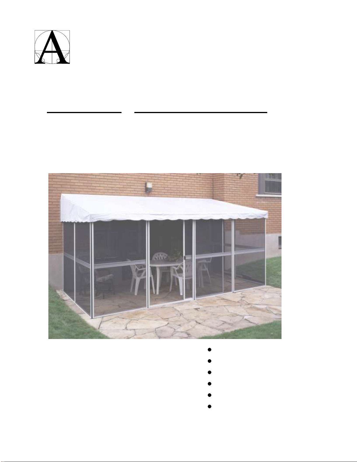
Rafter 1” x 1” Add a room Model No.
E0806 E1107 E1508 E1809 E2210 E2611 (96” at the wall)
G0806 G1107 G1508 G1809 G2210 G2611 (88” at the wall)
H0806 H1107 H1508 H1809 H2210 H2611 (107” at the wall)
CAUTION:
Before attempting to install
this Add-A-Room, read this
manual and follow all its
Safety Rules and Installation
Instructions.
Please don't destroy boxes until
completely assembled
Safety Instructions
Pre-assembly
Installation
Cleaning
Maintenance & Storing
Replacement Parts
Adlonco Holdings, Montreal, Quebec H4T 1K2
Form No. ZZZ-126 Rev 12012/01/12 L:\WP51\INSTRUCTIONS\GAZEBO INSTRUCTION BOOKS\ADLONCO\ADLONCO E SERIES ENGLISH Manual 2017.doc
Adlonco Holdings

Before attempting to install this Add-A-
Room, read this manual and follow all its
Safety Rules and Installation Instructions.
Keep open flames and flammable materials outside
and at a safe distance from your Add-A-Room.
Although the roof meets CPAI Code 84 requirements
for flame retardancy, it is NOT fireproof.
The roof must be removed during the winter season.
This Add-A-Room is NOT designed to support a snow
load.
Rain gutters on the house roof in the area above the
Add-A-Room are required to prevent possible damage
from excessive water accumulation on the roof.
Under certain conditions, the vinyl roof may display a
slight relaxing effect, causing slight depressions.
Should water collect in these depressions, remove it
by standing inside the Add-A-Room and pushing
upward and outward with a broom or other soft object
that will not damage the roof. Do not use a sharp
object that will cut the roof.
Remove the roof from your Add-A-Room if strong
winds or storms are forecasted to prevent damage to
the roof.
Do not attempt to assemble your Add-A-Room under
windy conditions to avoid damaging the components
and to prevent possible injury.
1. We recommend using two people to assemble and
install the Add-A-Room. It is safer and easier with two
people.
2. Check the height from your patio or deck. You must
have a height of at least 96” E series, 88” G series or
107” H series to install the roof.
3. Prepare a base for the Add-A-Room. It is critical that
the base be solid and level to allow you to install the
Add-A-Room properly and to prevent it from shifting
over time. The best base is concrete or a wooden
deck. At the very least, a weather resistant 2” x 4”.
4. As a minimum, you will need the following tools to
assemble and install your Add-A-Room:
Electric or cordless drill
1/8” & 5/32” drill bits
#2 Robertson (square) screwdriver
Medium sized slot screwdriver
9/16” wrench
Pliers
Cutting pliers or scissors
Stepladder
NOTE: You will need fasteners to anchor the Add-A-Room
to the base and to the wall of the house. As these
surfaces and fastener requirements vary widely, these
fasteners are not included with the hardware.
OPEN CARTONS
1. Open the long box and remove all components.
Check components against the parts list to make sure
all parts are present.
2. Open the wide box and remove the parts bag and
vinyl roof only.
Open parts bag and check components against
the parts list to make sure all parts are present.
Remove vinyl roof from the plastic bag, and hen
open up the roof on a clean dry surface with no
sharp objects. Leave vinyl roof in the direct sun so
it will become more pliable and easier to handle
during installation.
NOTE: Do not remove screen wall assembly from
the carton at this point.
INSTALL REAR ROOF TRACK
Install rear roof track to the wall of the house at exactly 96”
E series, 88” G series or 107” H series above the deck or
base you prepared for your Add-a-Room (see Fig.1).
NOTE: The rear roof track is shipped in two pieces. Make
sure they are butted firmly against each other and
perfectly aligned when installed.
1. Mark the wall at 96” E series, 88” G series or 107”
H series) above the deck or base (1).
2. Position rear roof track (2) with the top surface at the
marks.
3. Drill appropriate holes in flat section of the roof track
(3) to accommodate fasteners you will use to fasten
the rear track to the wall.
NOTE:
a) Make sure you use adequate fasteners and that
they are solidly anchored into the brick wall, wall studs
or wall sheeting. Fasteners should be spaced no more
than 16” apart.
b) For best results, use flat head screws and
countersink into the roof track.
CAUTION
!
SAFETY, PRE-ASSEMBLY & INSTALLATION
SAFETY
WARNING
!
PRE-ASSEMBLY
CAUTION
!
INSTALLATION
2

INSTALL REAR ROOF TRACK –cont’d
4. Draw a line (4) down the wall at each end of the rear
roof track.
NOTE: Line must be at 90oto the rear roof track.
5. Caulk if necessary at top of rail.
OPEN SCREEN WALL ASSEMBLY
1. Stand carton containing screen panels on its end and
carefully remove the screen wall assembly.
NOTE:
a) All screen sections are fastened together with vinyl
hinges.
b) Save carton for storing screen panels in off season.
2. Stand the screen wall assembly on end near the
location where it will be installed.
3. Open the screen sections like an accordion to form a
rough rectangle (See Fig. 2).
NOTE:
a) Make sure horizontal center bars on screen
sections are positioned in the inside of the structure.
b) If vinyl hinges slide up or down during handling,
slide them back into position.
DOOR LOCATION
The Add-A-Room is shipped from the factory with the door
located against the house wall (see Fig. 2 above). To
change the location of the door, proceed as follows:
1. Remove door frame (1) by sliding the vinyl hinge (2)
upward until it is removed from the door frame (see
Fig. 3).
2. Remove screen section where the door frame is to be
located by sliding the vinyl hinge on each side of the
screen section upward until they are removed from
the screen section.
3. Re-install door frame section and screen sections in
their new locations by re-inserting the vinyl hinges
from the top.
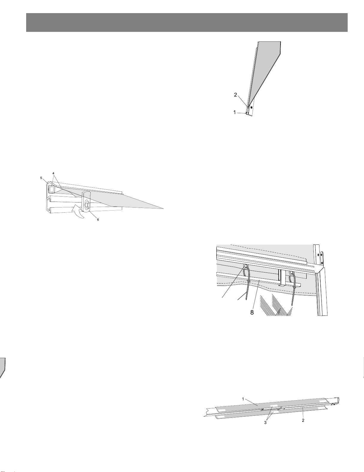
INSTALL DOOR TRACKS
1. Slide the lower plastic door track (1) into slot (2) in the
inside bottom section of door frame (3) (see Fig. 4).
NOTE: Continue to slide the plastic door track through
the door frame and into the slot of the adjoining
screen section until the end of the door track is 5”
from the edge of the door frame.
2. Install the upper plastic door track into the upper
section of the door frame, with the “U” section facing
downward.
INSTALL FOAM
Install self-adhesive foam insulation (1) to inside of both
vertical sections of the door frame (2) (see Fig. 5).
NOTE: Cut foam to length to fit each vertical.
INSTALLATION
Fig. 1
Fig. 2
Fig. 3
Fig. 4
Fig. 5
3

INSTALL DOOR & HANDLES
1. Slide door (wheels down) into plastic door tracks and
move it to the closed position.
2. With door fully closed, drill out center bar rivets and
locate the outer door handle (1) (with a 5/32 drill bit
where rivets have been removed (see Fig. 6).
NOTE: Door handle can be located at any height by
drilling 5/32” holes in the door at the desired height.
3. Install inner and outer door handles at holes (2) using
two machine screws (3) and nuts (4) provided.
.
FASTEN SCREEN SECTIONS TO HOUSE
1. Complete unfolding the screen sections into a
rectangle in the exact location you want to install your
Add-A-Room onto the base (see Fig. 7).
NOTE: At this point, make sure the screen sections in
each wall are lined up into a straight line and that
each wall is at right angles (90o) with each other.
2. Align the top of one wall against the house with the
outside edge of the screen frame 1¼” inside the
vertical mark on the wall (see Fig 8).
3. Slide stiffener (1) into top of wall section (2) with both
holes (3) above the screen panel.
4. Drill holes in wall and anchor stiffener firmly to the
wall.
NOTE: Screws for this activity are not supplied with
the kit.
5. Follow the same procedure for anchoring the second
end wall to the house.
NOTE: Make sure the outside edge of the screen
frame is 1¼” inside the vertical mark on the wall.
FASTEN SCREEN SECTIONS TO DECK OR BASE
1. Insert two hold down brackets (1) into the slot (2) in
the bottom of each screen panel (see Fig. 9).
NOTE: Place each hold down bracket on the inside of
the screen panel and about 6” from the edge.
2. Check alignment of panels to make sure each wall is
straight and that the end walls are at right angles (90o)
to the house wall and 1 ¼” inside lines on wall.
3. Fasten hold down brackets to the deck or base with
appropriate screws or fasteners (3) (not supplied).
NOTE: Holes in hold down bracket are predrilled to
accommodate #8 screws.
INSTALLATION
Fig. 6
Fig. 7
Fig. 8
4
Fig. 9

INSTALL FRONT AND SIDE TOP EXTRUSIONS
1. Install front top extrusion (1) onto top of front screen
panels (2) (see Fig. 10).
NOTE:
a) The front top extrusion is shipped in one or two
pieces. Make sure they are butted firmly against each
other and perfectly aligned when installed.
b) Adjust position of extrusions to leave the same
amount of overhang at each end (approximately 1¼”).
2. Carefully tap extrusion from the top to make sure it is
completely nested over the screen panels.
NOTE: Use a rubber hammer or a soft block of wood
to prevent damage to the extrusion.
3. Insert front rafter brackets (3) into slot in front top
extrusion (4). Position rafter brackets so they are
pointing upward.
NOTE:
a) Use rafter brackets with lighter “T” section.
b) Position rafter brackets so they are evenly spaced.
4. Insert one finger bracket (5) into the front top
extrusion at each end. Tighten into place at each end
with the finger pointing downward.
NOTE: Finger bracket must be placed inside each
end rafter bracket.
5. Insert hold down brackets (6) into the slots in the top
of the front screen panels (see Fig. 11).
NOTE: Space hold down brackets evenly across the
front top extrusion on the inside of the structure. If the
door track interferes, place hold down brackets at
each end of the door track.
6. Making sure the front top extrusion is still aligned and
fully nested onto the top of the screen panels, insert
self-tapping screws (8) using an electric or cordless
drill and appropriate screwdriver bit. You can also drill
a 1/8” hole (7) in the front top extrusion and fasten in
place using the self-tapping screws (8) provided.
NOTE: Do not over tighten the screw and strip the
aluminum threads.
7. Install side extrusions (1) onto top of screen panels (2)
of each side wall (see Fig. 12).
NOTE: Side extrusions should overhang the outside
of the screen panels.
8. Carefully tap extrusion from the top to make sure it is
completely nested over the screen panels and tight to
the wall of the house.
NOTE: Use a rubber hammer or a soft block of wood
to prevent damage to the extrusion.
9. Making sure the side top extrusion is still aligned and
fully nested onto the top of the screen panels; drill a
1/8” hole (3) in the side top extrusion and top of screen
panel. Fasten in place using the self tapping screws
(4) provided.
NOTE:
a) Use 4 screws evenly spaced along the extrusion.
b) Do not over tighten the screw and strip the
aluminum threads.
INSTALL RAFTER BRACKETS & FINGER CLIPS INTO
REAR ROOF TRACK
Alternately slide one finger bracket (1) and one rear rafter
bracket (2) into the slot provided in the rear roof track (see
Fig. 13). Space brackets equally along the rear roof track.
NOTE:
a) Use rafter brackets with heavier “T” section.
b) Make sure the rafter brackets are pointing downward.
c) Make sure one finger bracket is placed inside each
end rafter bracket to prevent outer rafter from moving
inward.
Fig. 10
Fig. 12
INSTALLATION
Fig. 12
5
Fig. 10
Fig. 11
Fig. 13

INSTALL SQUARE ROD HOLDERS AND RODS
1. Insert square rod holders (1) into slots in the bottom of
the front and side top extrusions (2) on the outside of
the screen panels (3) (see Fig 14).
NOTE: Equally space three rod holders above each
screen panel and the door.
2. Insert square rods (4) into square openings (5) in the
bottom of the rod holders.
INSTALL RAFTERS
1. Insert rafter splice (1) into rafter (2) and slide the
splice as far as it will go into the rafter (see Fig. 15).
2. With the slots in the rafter and splice (3) facing up,
insert the end of the rafter into the front rafter bracket
(4).
3. While holding the rafter firmly into the front rafter
bracket, carefully slide the splice out of the rafter and
into the rear rafter bracket (5).
NOTE: Slot in splice must be facing up.
4. Carefully drill one 1/8” hole through the bottom of the
rear rafter bracket (near house) through the splice.
NOTE: Make sure splice is fully inserted into the rafter
bracket before drilling.
5. Fasten rafter bracket to splice using self-tapping
screw (6).
6. Repeat steps #4 & #5 above and fasten the front
rafter bracket (near screen) to the rafter.
7. Repeat steps #1 through #7 and install the balance of
the rafter assemblies.
NOTE:
a) When all rafter assemblies are complete, position
the two end rafters directly above each end wall.
b) Tighten finger bracket against end rafter bracket.
c) Reposition the balance of the rafter assemblies so
they are evenly spaced.
8. Check to make sure tops of walls are aligned.
9. Lock all rafters and splices together by drilling a 1/8”
hole (7) through both the rafter and splice and
inserting self-tapping screw.
INSTALL ROOF
Do not attempt to install the roof in windy conditions
as a sudden gust of wind could cause you to fall or
tear the roofing material.
Read all roof installation instructions before
proceeding with installation.
1. Earlier in this Owner’s Manual, instructions were given
to open the roof package and allow the sun to warm
the vinyl to make it flexible. If this was not done, do it
now and allow adequate time for the vinyl to warm. If
there is not enough sunlight to warm the vinyl at this
time, wait until a sunny day is available.
2. Unfold the roof fabric and lift it up over the front top
extrusions and onto the rafters. Completely unfold the
fabric and allow it to relax while resting on the rafters.
3. Loosen all finger brackets in the rear roof track and
turn the fingers so they point downward.
4. Slide the remaining square rods (1) into the sewn-in
rod pockets (2) at the rear edge of the roof fabric until
they meet (see Fig. 16).
NOTE: Make sure the edge of the rod pocket material
(3) is on the under side of the roof.
5. Carefully slide the roof up the rafters until the rod
pocket reaches the rear roof track.
Fig. 14
CAUTION
!
Fig. 16
INSTALLATION
6
Fig. 15
7
INSTALL ROOF –cont’d
6. Beginning at one end, push the square rod and rod
pocket (4) into the slot (5) in the upper part of the rear
roof track (see Fig. 17.).
NOTE: Make sure the end of the square rod and rod
pocket are to the end of the rear roof track.
7. While holding the square rod and rod pocket in the
slot, carefully turn the end finger bracket (6) so it
points upward to hold the rod and pocket in place.
NOTE: Be careful when turning the finger bracket
upward. If it is too tight while turning you will cut the
fabric.
8. Complete installing the rod and pocket into the slot in
the rear roof track at each finger joint as noted in #7
above.
9. When all finger brackets are turned up, tighten the
nuts at all finger brackets using a 9/16” wrench.
NOTE: Nuts should be snug but not so tight that the
finger bracket will cut the fabric.
10. Pull the roof tightly toward the front and down over the
front top extrusions.
NOTE: Make sure the front top and side top
extrusions have no sharp edges that will cut the roof
fabric. Any sharp edges should be carefully filed or
sanded smooth.
INSTALL C-CHANNEL
1. Slide aluminum C-channel (1) over the plastic bead
(2) on the rear of one roof side panel (see Fig. 18).
2. Drill one hole in each end and in the center of the C-
channel (3) and fasten the C-channel to the house
wall using appropriate fasteners (not supplied).
3. Repeat steps #1 and #2 to install the C-channel on
the second roof side panel.
11.
INSTALL ROOF TIE DOWN STRAPS
1. When roof fabric is tightly pulled over the top front
extrusions, fasten in place using the roof tie down
straps provided (see Fig. 19).
NOTE:
a) Insert each roof tie down strap (7) under the square
rod (8) and then through the gromet (9).
b) Do not fully tighten roof tie down straps until the
roof fabric has had sufficient time to stretch into place.
2. Once roof fabric has had several days to stretch into
place, tighten all roof tie down straps evenly around
the roof and cut off the excess tie material with
scissors.
FASTEN WIND TIE-DOWN CLOSURES
On the under side of the roof, you will find two or three
wind tie-downs that will fasten the roof to the rafters. Wrap
these tie-downs (1) around the corresponding rafter (2)
and fasten with the hook and loop closures at each end
and in the middle of the tie-down (see Fig. 20).
Install rafters
Show splicer with screw in bracket
Show screw in splicer
Fig. 12
Fig. 17
Fig. 19
Fig. 20
INSTALLATION
7
Fig. 18
7
9
3

LEAKS
NOTE: It is normal for small needle holes to be visible
where vinyl has been stitched. Unlike cloth fabrics, vinyl
material will not contract after being pierced with a sewing
needle. Although these needle holes are so small they
seldom leak, a small amount of water may leak through
the small needle holes during the first several rains.
However, the cotton wrapped thread that is used in the
sewing process will expand when it gets wet, closing the
needle holes and eliminating any leaks. If any leaks
persist, simply apply a liquid sealer that is used to seal
tent seams (not supplied).
CLEANING
Clean roof using a mild detergent in water and a medium
bristle brush. Rinse thoroughly after cleaning to remove all
detergent residue.
Disassemble and store the Add-A-Room during the
winter. The Add-A-Room is not designed to withstand
cold winter weather and related snow loads.
Make sure roof is clean and dry before folding for
storage. Be absolutely sure the fabric and rib webs are
completely dry before folding. Moisture will cause rot and
mildew.
Disassemble the Add-A-Room by reversing the order of
the “installation” steps described in this Owner’s Manual.
Carefully fold screen and door sections and store them in
the original shipping carton to protect them from damage.
GENERAL
All replacement parts are guaranteed to be as
represented. We will always do our very best to fill your
parts order promptly. However, from time to time, our
ability to fill your orders promptly may be beyond our
control. We cannot accept liability for delays and delivery
failures such as delays by carriers, accidents, strikes and
any other such unavoidable causes.
We may be forced to partially fill your order and back-
order the balance. Should this happen, please bear with
us, we will complete your order as quickly as possible.
If it becomes necessary to supply a substitute part, we will
not do so without your written approval.
ORDERING PARTS
Orders for replacement parts may be placed by:
Telephone: (514) 276-3492
Toll Free Telephone: (800) 737-7174
Fax: (514) 276-4147
E-mail: info@adloncoholdings.com
Please include the following with your replacement parts
order:
Full name
Shipping address
Telephone number
Part Key #
Part #
Part description
Quantity of each part
Newfoundland, Nova Scotia & New Brunswick residents
add H.S.T.
Quebec residents add G.S.T. and P.S.T.
Other provinces add G.S.T.
Add $15.00 minimum or 5% of purchase order to each
order for shipping and handling.
Minimum order - $25.00
No C.O.D. shipments will be made.
RETURNS POLICY
No returns will be accepted for credit without prior written
authorization.
All returns must be prepaid.
MAINTENANCE, STORING & PARTS
STORING
PARTS AVAILABILITY
MAINTENANCE
8

REPLACEMENT PARTS
9

Key #
Part #
Description 96” at the wall
Quantity
Price
E1107
E1508
E1809
E2210
E2611
1
96-156
Rear Roof Track 91 1/8”
2
$49.20
1
04-279
Rear Roof Track 41 ½”
1
$57.00
1
96-158
Rear Roof Track 113 ½”
2
$75.58
1
96-159
Rear Roof Track 135 7/8”
2
$90.48
1
96-160
Rear Roof Track 137 ½”
1
2
$91.50
2
96-161
Square Rod 91 1/8”
4
$15.97
2
96-162
Square Rod 105 ½”
6
$18.49
2
96-163
Square Rod 113 ½”
4
$19.89
2
04-280
Square Rod 135 7/8”
4
$23.81
2
96-165
Square Rod 137 ½”
2
$24.10
3
94-096
Finger Clip
9
11
13
15
17
$3,58
4
98-451
Rear Rafter Bracket
7
9
11
13
15
$3,80
5
94-133
Self Tapping Screw
35
38
41
44
47
$0,64/2
6
98-456
Rafter Splice 24”
7
9
11
13
15
$14.00
7
98-455
Rafter 77 ¼”
7
9
11
13
15
$35.16
8
98-450
Front Rafter Bracket
7
9
11
13
15
$ 3.80
9
04-281
Front Top Extrusion 44 ½”
1
$ 61.90
9
04-282
Front Top Extrusion 41 ½ ”
1
$ 57.73
9
96-153
Front Top Extrusion 113 ½”
2
$112.77
9
96-154
Front Top Extrusion 135 7/8”
2
$189.00
9
96-155
Front Top Extrusion 137 ½”
1
1
2
$191.26
10
94-116
Square Rod Holder
21
24
37
30
33
$6.52
11
85-057
Frame with Screening
6
7
8
9
10
$168.00
12
85-011
Vinyl Hinge
6
7
8
9
10
$ 9.50
13
94-129
Roof Tie Down Strap
47
53
57
65
71
$3.16 /25
14
94-171
Front Top Extrusion Hold Down Bracket
4
6
8
10
12
$ 6.40 /2
15
85-008
Hold Down Bracket
12
14
16
18
20
$ 6.30 /6
16
96-348
Side Top Extrusion 86”
2
2
2
2
2
$ 79.00
17
85-056
Plastic Door Track
2
2
2
2
2
$ 19.11
18
85-051
Sliding Door with Screening & Wheels
1
1
1
1
1
$187.79
19
85-050
Door Handle
2
2
2
2
2
$ 7.43 /2
20
85-024
Door Handle Machine Screw 1 ¼”
2
2
2
2
2
$ 0.66 /2
21
85-025
Door Handle Machine Screw Nuts
2
2
2
2
2
$ 0.59 /2
22
85-058
Weather Strip
1
1
1
1
1
$ 9.42
23
85-020
Aluminum Stiffener
2
2
2
2
2
$ 2.90
24
85-064
Aluminum “C” Channel 22”
2
2
2
2
2
$ 4.20
25
96-349
Side Square Rod 89 ½”
2
2
2
2
2
$ 21.96
96-E36
Roof for E1107
1
$ 545.91
96-E39
Roof for E1508
1
$ 606.04
96-E42
Roof for E1809
1
$ 663.59
96-E45
Roof for E2210
1
$ 752.79
96-E48
Roof for E2611
1
$ 827.28
Additional Components Available
85-001
Rolling Door Wheel Assembly
$ 15.68
85-052
Door Frame (without screen)
$136.50
85-014
Replacement Fiberglass 44” x 75”
$ 16.80
85-015
“T” Spline to retain cloth
$ 6.30
85-018
Replacement Fabric for privacy panel 44” (Beige) discontinue
$ 15.20
85-019
Replacement Fabric for privacy panel 44” (Clear)
$ 15.20
03-576
Replacement Fabric for privacy panel 44” (White)
$ 15.20
85-022
Bottom Spring for privacy panel
$ 2.50/2
85-023
Handle for privacy panel
$ 5.10/2
85-099
Replacement Privacy Panel 44” (White) 34 ½” x 42”
$ 56.64
85-100
Replacement Privacy Panel for sliding door (White) 33 13/16”x 42”
$ 56.64
85-101
Replacement Privacy Panel 44” (Clear) 34 ½” x 42”
$ 56.64
85-102
Replacement Privacy Panel for sliding door (Clear) 33 13/16” x 42”
$ 56.64
94-030
Bolts 3/8” and nuts
$ 3.20/6
PRICES SUBJECT TO CHANGE
Form No. ZZZ-126 REV1 2012/01/12 L:\WP51\INSTRUCTIONS\GAZEBO INSTRUCTION BOOKS\ADLONCO\ADLONCO E SERIES ENGLISH Manual 2017.doc
REPLACEMENT PARTS
10

Key #
Part #
Description 88” at the wall
Quantity
Price
G1107
G1508
G1809
G2210
G2611
1
96-156
Rear Roof Track 91 1/8”
2
$ 60.68
1
04-279
Rear Roof Track 41 ½”
1
$ 38.69
1
96-158
Rear Roof Track 113 ½”
2
$ 75.58
1
96-159
Rear Roof Track 135 7/8”
2
$ 90.48
1
96-160
Rear Roof Track 137 ½”
1
2
$ 91.56
2
96-161
Square Rod 91 1/8”
4
$ 15.97
2
96-162
Square Rod 105 ½”
6
$ 18.49
2
96-163
Square Rod 113 ½”
4
$ 19.89
2
04-280
Square Rod 135 7/8”
4
$ 23.81
2
96-165
Square Rod 137 ½”
2
$ 24.10
3
94-096
Finger Clip
9
11
13
15
17
$ 3.58
4
98-451
Rear Rafter Bracket
7
9
11
13
15
$ 3.80
5
94-133
Self Tapping Screw
35
38
41
44
47
$ 0.64/2
6
98-456
Rafter Splice 24”
7
9
11
13
15
$ 14.00
7
04-283
Rafter 76 ½”
7
9
11
13
15
$ 34.82
8
98-450
Front Rafter Bracket
7
9
11
13
15
$ 3.80
9
04-281
Front Top Extrusion 44½”
1
$ 61.90
9
04-282
Front Top Extrusion 41 ½ ”
1
$ 57.73
9
96-153
Front Top Extrusion 113 ½”
2
$ 112.77
9
96-154
Front Top Extrusion 135 7/8”
2
$ 189.00
9
96-155
Front Top Extrusion 137 ½”
1
1
2
$ 191.26
10
94-116
Square Rod Holder
21
24
27
30
33
$ 6.52
11
85-057
Frame with Screening
6
7
8
9
10
$ 168.00
12
85-011
Vinyl Hinge
6
7
8
9
10
$ 9.50
13
94-129
Roof Tie Down Strap
47
53
57
65
71
$ 3.16 /25
14
94-171
Front Top Extrusion Hold Down
Bracket
4
6
8
10
12
$ 6.40/2
15
85-008
Hold Down Bracket
12
14
16
18
20
$ 6.30/6
16
96-348
Side Top Extrusion 86”
2
2
2
2
2
$ 79.00
17
85-056
Plastic Door Track
2
2
2
2
2
$ 19.11
18
85-051
Sliding Door with Screening & Wheels
1
1
1
1
1
$ 187.79
19
85-050
Door Handle
2
2
2
2
2
$ 7.43/2
20
85-024
Door Handle Machine Screw 1 ¼”
2
2
2
2
2
$ 0.66/2
21
85-025
Door Handle Machine Screw Nuts
2
2
2
2
2
$ 0.59/2
22
85-058
Weather Strip
1
1
1
1
1
$ 9.42
23
85-020
Aluminum Stiffener
2
2
2
2
2
$ 2.90
24
85-064
Aluminum “C” Channel 22”
2
2
2
2
2
$ 4.20
25
96-349
Side Square Rod 89 ½”
2
2
2
2
2
$ 21.96
96-G36
Roof for G1107
1
$ 545.91
96-G39
Roof for G1508
1
$ 606.04
96-G42
Roof for G1809
1
$ 663.59
96-G45
Roof for G2210
1
$ 752.79
96-G48
Roof for G2611
1
$ 827.28
Additional Components Available
85-001
Rolling Door Wheel Assembly
$ 15.68
85-052
Door Frame (without screen)
$136.50
85-014
Replacement Fiberglass 44” x 75”
$ 16.80
85-015
“T” Spline to retain cloth
$ 6.30
85-018
Replacement Fabric for privacy panel 44” (Beige) Discontinue
$ 15.20
85-019
Replacement Fabric for privacy panel 44” (Clear)
$ 15.20
03-576
Replacement Fabric for privacy panel 44” (White)
$ 15.20
85-022
Bottom Spring for privacy panel
$ 2.50/2
85-023
Handle for privacy panel
$ 5.10/2
85-099
Replacement Privacy Panel 44” (White) 34 ½” x 42”
$ 56.64
85-100
Replacement Privacy Panel for sliding door (White) 33 13/16”x 42”
$ 56.64
85-101
Replacement Privacy Panel 44” (Clear) 34 ½” x 42”
$ 56.64
85-102
Replacement Privacy Panel for sliding door (Clear) 33 13/16” x 42”
$ 56.64
94-030
Bolts 3/8” and nuts
$ 3.20/6
PRICES SUBJECT TO CHANGE
Form No. ZZZ-126 REV1 2012/01/12 L:\WP51\INSTRUCTIONS\GAZEBO INSTRUCTION BOOKS\ADLONCO\ADLONCO E SERIES ENGLISH Manual 2017.doc
REPLACEMENT PARTS
11

Key #
Part #
Description 107” at the wall
Quantity
Price
H1107
H1508
H1809
H2210
H2611
1
96-156
Rear Roof Track 91 1/8”
2
$ 60.68
1
04-279
Rear Roof Track 41 ½”
1
$ 38.69
1
96-158
Rear Roof Track 113 ½”
2
$ 75.58
1
96-159
Rear Roof Track 135 7/8”
2
$ 90.48
1
96-160
Rear Roof Track 137 ½”
1
2
$ 91.56
2
96-161
Square Rod 91 1/8”
4
$ 15.97
2
96-162
Square Rod 105 ½”
6
$ 18.49
2
96-163
Square Rod 113 ½”
4
$ 19.89
2
04-280
Square Rod 135 7/8”
4
$ 23.81
2
96-165
Square Rod 137 ½”
2
$ 24.10
3
94-096
Finger Clip
9
11
13
15
17
$ 3.58
4
98-451
Rear Rafter Bracket
7
9
11
13
15
$ 3.80
5
94-133
Self Tapping Screw
35
38
41
44
47
$ 0.64/2
6
98-456
Rafter Splice 24”
7
9
11
13
15
$ 14.00
7
04-284
Rafter 78 ¼”
7
9
11
13
15
$ 35.62
8
98-450
Front Rafter Bracket
7
9
11
13
15
$ 3.80
9
04-281
Front Top Extrusion 44½”
1
$ 61.90
9
04-282
Front Top Extrusion 41 ½ ”
1
$ 57.73
9
96-153
Front Top Extrusion 113 ½”
2
$ 112.77
9
96-154
Front Top Extrusion 135 7/8”
2
$ 135.00
9
96-155
Front Top Extrusion 137 ½”
1
1
2
$ 136.61
10
94-116
Square Rod Holder
21
24
27
30
33
$ 6.52
11
85-057
Frame with Screening
6
7
8
9
10
$ 168.00
12
85-011
Vinyl Hinge
6
7
8
9
10
$ 9.50
13
94-129
Roof Tie Down Strap
47
53
57
65
71
$ 3.16 /25
14
94-171
Front Top Extrusion Hold Down
Bracket
4
6
8
10
12
$ 6.40/2
15
85-008
Hold Down Bracket
12
14
16
18
20
$ 6.30/6
16
96-348
Side Top Extrusion 86”
2
2
2
2
2
$ 79.00
17
85-056
Plastic Door Track
2
2
2
2
2
$ 19.11
18
85-051
Sliding Door with Screening & Wheels
1
1
1
1
1
$ 187.79
19
85-050
Door Handle
2
2
2
2
2
$ 7.43/2
20
85-024
Door Handle Machine Screw 1 ¼”
2
2
2
2
2
$ 0.66/2
21
85-025
Door Handle Machine Screw Nuts
2
2
2
2
2
$ 0.59/2
22
85-058
Weather Strip
1
1
1
1
1
$ 9.42
23
85-020
Aluminum Stiffener
2
2
2
2
2
$ 2.90
24
85-064
Aluminum “C” Channel 22”
2
2
2
2
2
$ 4.20
25
96-349
Side Square Rod 89 ½”
2
2
2
2
2
$ 21.96
96-H36
Roof for H1107
1
$ 545.91
96-H39
Roof for H1508
1
$ 606.04
96-H42
Roof for H1809
1
$ 663.59
96-H45
Roof for H2210
1
$ 752.79
96-H48
Roof for H2611
1
$ 827.28
Additional Components Available
85-001
Rolling Door Wheel Assembly
$ 15.68
85-052
Door Frame (without screen)
$136.50
85-014
Replacement Fiberglass 44” x 75”
$ 16.80
85-015
“T” Spline to retain cloth
$ 6.30
85-018
Replacement Fabric for privacy panel 44” (Beige) Discontinue
$ 15.20
85-019
Replacement Fabric for privacy panel 44” (Clear)
$ 15.20
03-576
Replacement Fabric for privacy panel 44” (White)
$ 15.20
85-022
Bottom Spring for privacy panel
$ 2.50/2
85-023
Handle for privacy panel
$ 5.10/2
85-099
Replacement Privacy Panel 44” (White) 34 ½” x 42”
$ 56.64
85-100
Replacement Privacy Panel for sliding door (White) 33 13/16” x 42”
$ 56.64
85-101
Replacement Privacy Panel 44” (Clear) 34 ½” x 42”
$ 56.64
85-102
Replacement Privacy Panel for sliding door (Clear) 33 13/16” x 42”
$ 56.64
94-030
Bolts 3/8” and nuts
$ 3.20/6
PRICES SUBJECT TO CHANGE
Form No. ZZZ-126 REV1 2012/01/12 L:\WP51\INSTRUCTIONS\GAZEBO INSTRUCTION BOOKS\ADLONCO\ADLONCO E SERIES ENGLISH Manual 2017.doc
REPLACEMENT PARTS
12
This manual suits for next models
17
Table of contents
Other Adlonco Holdings Tent manuals


Popular Tent manuals by other brands

Coleman
Coleman 2000007825 Setup instructions

Summit Treestands
Summit Treestands Run-N-Gun Ground Blind Setup instructions

White Duck Outdoors
White Duck Outdoors Alpha Wall Tent Series owner's manual

Kiwi Camping
Kiwi Camping Kakapo 8 Pitching instructions

DARCHE
DARCHE T050801200A instruction manual

Gill
Gill 881018 Assembly instructions

ShelterLogic
ShelterLogic 58432 Assembly & instruction manual

Extreme marquees
Extreme marquees PAVILION Instructions & Care

Quik Shade
Quik Shade Go Hybrid user manual

Jack Wolfskin
Jack Wolfskin TRAVEL LODGE RT Assembly instructions

Inventini
Inventini Pascal user manual

Caravan canopy
Caravan canopy MAGNUM Series Reference manual


