manuals.online logo
Brands
  1. Home
  2. •
  3. Brands
  4. •
  5. Novus
  6. •
  7. Transmitter
  8. •
  9. Novus NP400 User manual

Novus NP400 User manual

This manual suits for next models

10

Other Novus Transmitter manuals

Novus RHT-WM User manual

Novus

Novus RHT-WM User manual

Novus TxIsoPack-HART User manual

Novus

Novus TxIsoPack-HART User manual

Novus TxIsoRail 0-10 Vdc User manual

Novus

Novus TxIsoRail 0-10 Vdc User manual

Novus TxRail-USB User manual

Novus

Novus TxRail-USB User manual

Novus TxBlock-USB User manual

Novus

Novus TxBlock-USB User manual

Novus TxIsoBlock-HRT User manual

Novus

Novus TxIsoBlock-HRT User manual

Novus TxIsoPack User manual

Novus

Novus TxIsoPack User manual

Novus TxRail-USB User manual

Novus

Novus TxRail-USB User manual

Novus NVPT-131VTP-HD User manual

Novus

Novus NVPT-131VTP-HD User manual

Novus NP785 User manual

Novus

Novus NP785 User manual

Novus TXMINI-DIN43650 User manual

Novus

Novus TXMINI-DIN43650 User manual

Novus RHT-WM-485-LCD User manual

Novus

Novus RHT-WM-485-LCD User manual

Novus TxIsoRail-HRT User manual

Novus

Novus TxIsoRail-HRT User manual

Novus NP640 User manual

Novus

Novus NP640 User manual

Novus TxIsoRail User manual

Novus

Novus TxIsoRail User manual

Novus TxRail User manual

Novus

Novus TxRail User manual

Novus TXMINI-M12-485 User manual

Novus

Novus TXMINI-M12-485 User manual

Novus RHT-WM-485-LCD User manual

Novus

Novus RHT-WM-485-LCD User manual

Novus TL400-I User manual

Novus

Novus TL400-I User manual

Novus TxRail User manual

Novus

Novus TxRail User manual

Novus TxIsoRail0-10Vdc User manual

Novus

Novus TxIsoRail0-10Vdc User manual

Novus NP600 User manual

Novus

Novus NP600 User manual

Novus TXMINI-M12 User manual

Novus

Novus TXMINI-M12 User manual

Novus DigiRail-VA User manual

Novus

Novus DigiRail-VA User manual

Popular Transmitter manuals by other brands

Seneca K120RTD installation manual

Seneca

Seneca K120RTD installation manual

Nautel GV40 installation manual

Nautel

Nautel GV40 installation manual

HumanTechnik cm-light operating instructions

HumanTechnik

HumanTechnik cm-light operating instructions

INOR APAQ C130 TC User instructions

INOR

INOR APAQ C130 TC User instructions

Linear DXS-64 operating instructions

Linear

Linear DXS-64 operating instructions

FeinTech ABT00102 instruction manual

FeinTech

FeinTech ABT00102 instruction manual

Geo Web Pack quick start guide

Geo

Geo Web Pack quick start guide

Inovonics EchoStream EN1210W installation instructions

Inovonics

Inovonics EchoStream EN1210W installation instructions

IKONNIK KA-6 quick start guide

IKONNIK

IKONNIK KA-6 quick start guide

Rohde & Schwarz SR8000 Series System manual

Rohde & Schwarz

Rohde & Schwarz SR8000 Series System manual

Audio Technica UniPak ATW-T93 Installation and operation

Audio Technica

Audio Technica UniPak ATW-T93 Installation and operation

NIVELCO EasyTREK SCA-300 Series Programming manual

NIVELCO

NIVELCO EasyTREK SCA-300 Series Programming manual

Honeywell 5816WMBR installation instructions

Honeywell

Honeywell 5816WMBR installation instructions

Kamstrup READy MTU Installation and operation guide

Kamstrup

Kamstrup READy MTU Installation and operation guide

Omega ZW Series user guide

Omega

Omega ZW Series user guide

ABB Field 264H Instructions for installation

ABB

ABB Field 264H Instructions for installation

Dejero EnGo 3x manual

Dejero

Dejero EnGo 3x manual

Rosemount 4600 Reference manual

Rosemount

Rosemount 4600 Reference manual

manuals.online logo
manuals.online logoBrands
  • About & Mission
  • Contact us
  • Privacy Policy
  • Terms and Conditions

Copyright 2025 Manuals.Online. All Rights Reserved.

NOVUS AUTOMATION 1/2
NP
400
RELATIVE PRESSURE TRANSMITTER
– INSTRUCTIONS MANUAL – V1.0x A
INTRODUCTION
The NP400 relative pressure transmitters are robust and reliable
equipment suitable for general industrial applications. They are
available in several measuring ranges and process connection
threads.
PRECAUTION
Before operating the transmitter, carefully read its specifications and
operating instructions. In case of damage caused by incorrect
operation or inappropriate usage, and its consequences, warranty
becomes ineffective and null.
A specialized professional shall perform the installation.
A specific electrical power supply network should be provided for
instruments use only.
UNPACKING
After unpacking the product, besides the transmitter it must be
available:
•A quick guide to installation and operation.
•A sealed electrical connector.
•A screw to fix the connector to the transmitter.
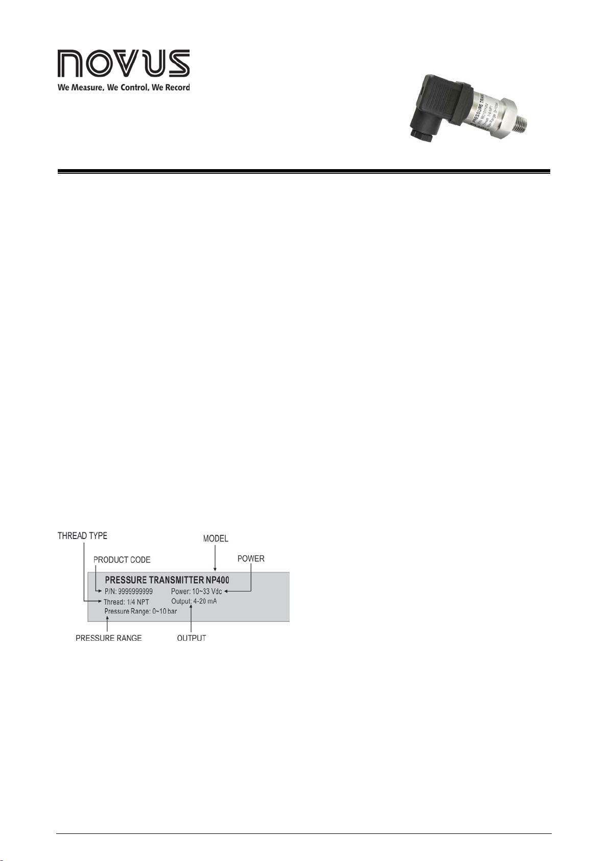
IDENTIFICATION
An identification label is attached to the equipment housing. On this
label, you can found detailed information about the transmitter.
Fig. 1 shows the identification label.
Fig. 1 – Transmitter identification
SPECIFICATIONS
Pressure Range:
0-2 / 0-5 / 0-10 / 0-20 / 0-50 / 0-100 bar (*)
Measurement Accuracy:
< ±0.5 % pressure range
< ±1.0 % pressure range for 0~100 bar model
Including linearity, hysteresis and repeatability, in 25 °C
Thermal Deviation Maximum:
< ± 0.06 % the span / °C
Overpressure Range:
Twice the pressure range upper value.
Rupture Pressure:
Three times the pressure range upper value.
Output Signal (Output):
Electric current, 4-20 mA, 2 wires.
Power Supply (Power):
10 to 33 Vdc
Maximum Load (RL):
RL= (Vdc - 10) / 0.02 (Ω)
Where: Vdc= Power supply voltage
Electrical Connection:
Connector for Type A valves (DIN EN 175301-803), IP65.
Conductor 1.5 mm² (max.) and cables between 6 and 8 mm in
diameter.
Operating Temperature:
-20 to 70 °C
Medium Temperature:
-20 to 100 °C
Dynamic Response:
< 30 ms
Process Connection (Thread):
¼ NPT; ½ NPT; ½ BSP (*)
Materials:
Metal housing of the transmitter:............................Stainless steel 316
Sensor:...............................................................Ceramic (Al2O396 %)
Sealing ring:...................................................................................FKM
Wetted parts:
Sensor (Ceramic), sealing ring (FKM) and metal connection
(stainless steel 316).
Compatibility:Any gas or liquid compatible with the constituent
materials of the wetted parts.
(*) Information available on the product identification label.
Pressure Transmitter NP400
NOVUS AUTOMATION 2/2
ELECTRICAL CONNECTIONS
Fig. 2 – Electrical connections
Installation recommendations
•The instruments must be powered from a dedicated
instrumentation power supply.
•It is strongly recommended to apply RC'S FILTERS (noise
suppressor) to contactor coils, solenoids, etc.
•To improve measurement stability, immunity and safety, it is
recommended to use system grounding.
DIMENSIONS
Fig. 3 – Transmitter dimensions
THREAD A (mm) B (mm) WEIGHT (g)
NPT ¼ 15.5 52.5 106
NPT ½ 20.0 57 159
BSP ½ 15.0 52 121
Table 1 – Transmitter thread type, dimensions and weight
WARRANTY
Warranty conditions are on our website
www.novusautomation.com/warranty.