manuals.online logo
Brands
  1. Home
  2. •
  3. Brands
  4. •
  5. ADTRAN
  6. •
  7. Network Card
  8. •
  9. ADTRAN 239 H4R User manual

ADTRAN 239 H4R User manual

Other manuals for 239 H4R

2

Other ADTRAN Network Card manuals

ADTRAN 239 T1 HDSL4 Instruction Manual

ADTRAN

ADTRAN 239 T1 HDSL4 Instruction Manual

ADTRAN HRE/T200 User manual

ADTRAN

ADTRAN HRE/T200 User manual

ADTRAN 3192 H2TU-C User manual

ADTRAN

ADTRAN 3192 H2TU-C User manual

ADTRAN 3000 NTU-8 Instruction Manual

ADTRAN

ADTRAN 3000 NTU-8 Instruction Manual

ADTRAN NetVanta 8044M User manual

ADTRAN

ADTRAN NetVanta 8044M User manual

ADTRAN DDM+ H2TU-C Instruction Manual

ADTRAN

ADTRAN DDM+ H2TU-C Instruction Manual

ADTRAN 900 Series User manual

ADTRAN

ADTRAN 900 Series User manual

ADTRAN U-BR1TE User manual

ADTRAN

ADTRAN U-BR1TE User manual

ADTRAN ATLAS 550 User manual

ADTRAN

ADTRAN ATLAS 550 User manual

ADTRAN NetVanta Internet-Based WAN Backup User manual

ADTRAN

ADTRAN NetVanta Internet-Based WAN Backup User manual

ADTRAN TRACER Protection Switch User manual

ADTRAN

ADTRAN TRACER Protection Switch User manual

ADTRAN 5000 Series Operating manual

ADTRAN

ADTRAN 5000 Series Operating manual

ADTRAN ATLAS 800 Series Module Nx56/64 Bonding User manual

ADTRAN

ADTRAN ATLAS 800 Series Module Nx56/64 Bonding User manual

ADTRAN 20 Ohm Adapter User manual

ADTRAN

ADTRAN 20 Ohm Adapter User manual

ADTRAN AHDSL2 Instruction Manual

ADTRAN

ADTRAN AHDSL2 Instruction Manual

ADTRAN 3000 HTU-C User manual

ADTRAN

ADTRAN 3000 HTU-C User manual

ADTRAN 3.125 Gigabit Ethernet User manual

ADTRAN

ADTRAN 3.125 Gigabit Ethernet User manual

ADTRAN DS3 User manual

ADTRAN

ADTRAN DS3 User manual

ADTRAN TRACER 6000 SERIES User guide

ADTRAN

ADTRAN TRACER 6000 SERIES User guide

ADTRAN TSU 600 User manual

ADTRAN

ADTRAN TSU 600 User manual

ADTRAN 3192 H4TU-C User manual

ADTRAN

ADTRAN 3192 H4TU-C User manual

ADTRAN ATLAS 800PLUS User manual

ADTRAN

ADTRAN ATLAS 800PLUS User manual

ADTRAN AHT1U User manual

ADTRAN

ADTRAN AHT1U User manual

ADTRAN NetVanta 1000R Series Operating manual

ADTRAN

ADTRAN NetVanta 1000R Series Operating manual

Popular Network Card manuals by other brands

Belkin F6D301 user manual

Belkin

Belkin F6D301 user manual

FirstComm OBiWiFi5G Setup guide

FirstComm

FirstComm OBiWiFi5G Setup guide

TRENDnet TU2-ETG user guide

TRENDnet

TRENDnet TU2-ETG user guide

YASKAWA SI-EN3 Technical manual

YASKAWA

YASKAWA SI-EN3 Technical manual

Paradyne BitStorm 2600 IP DSLAM installation guide

Paradyne

Paradyne BitStorm 2600 IP DSLAM installation guide

Belkin F5D7050 user manual

Belkin

Belkin F5D7050 user manual

3Com EtherLink 3C509B quick guide

3Com

3Com EtherLink 3C509B quick guide

TRENDnet TEG-PCITX user guide

TRENDnet

TRENDnet TEG-PCITX user guide

Cisco MC16E installation guide

Cisco

Cisco MC16E installation guide

Delta Electronics Braking Modules VFDB Series instruction sheet

Delta Electronics

Delta Electronics Braking Modules VFDB Series instruction sheet

TwinMOS Booming user manual

TwinMOS

TwinMOS Booming user manual

Dialogic Media Board DM/V1200BTEPEQ installation guide

Dialogic

Dialogic Media Board DM/V1200BTEPEQ installation guide

Buffalo AirStation WLI-PCM-L11GP user manual

Buffalo

Buffalo AirStation WLI-PCM-L11GP user manual

TRENDnet TEG-PCITXR user guide

TRENDnet

TRENDnet TEG-PCITXR user guide

Sun Microsystems Interface Adapter user guide

Sun Microsystems

Sun Microsystems Interface Adapter user guide

D-Link DHP?P309AV Setup guide

D-Link

D-Link DHP?P309AV Setup guide

Extollo LANPlug 2000 Product guide

Extollo

Extollo LANPlug 2000 Product guide

LG-Ericsson PCI-1020 user manual

LG-Ericsson

LG-Ericsson PCI-1020 user manual

manuals.online logo
manuals.online logoBrands
  • About & Mission
  • Contact us
  • Privacy Policy
  • Terms and Conditions

Copyright 2025 Manuals.Online. All Rights Reserved.

JOBAID
239 H4R
CLEI: T1R5YP3D_ _
239 H4R
1221445L1
LP1 NET
LP2
LP1
LP2
LL RL
(Y) (G)
/
CUST
61221445L1-22B
0205
CARD EDGE PIN ASSIGNMENTS
LOOPBACK AND CONTROL CODES
Refer to the Installation and Maintenance Practice of the H4TU-C or H4TU-R used in
the circuit for a list of loopback codes.
■ For a complete Installation and Maintenance Practice (P/N 61221445L1-5) faxback: (877) 457-5007, faxback Document 755. Please have your fax number ready. ■
C A U T I O NC A U T I O N !
SUBJECT TO ELECTROSTATIC DAMAGE
OR DECREASE IN RELIABILITY.
HANDLING PRECAUTIONS REQUIRED.
STATUS LEDs
LP1/LP2 NET ●●Off No span power present
●Solid Green Synchronized with an SNR margin greater than the user defined SNR
Margin Alarm Threshold
✷Fast Blinking (Blinking 3 times per second) Attempting to synchronize with the
Green H4TU-C
✷Slow Blinking (Blinking 1 time per second) Synchronized with an SNR margin
Green greater than the user defined SNR Margin Alarm Threshold and the
pulse attenuation is greater than the user defined Loop Attenuation
Alarm Threshold
●Solid Yellow Synchronized with an SNR margin greater than 0 dB but less than
the user defined SNR Margin Alarm Threshold
✷Slow Blinking Synchronized with an SNR margin greater than 0 dB but less than the
Yellow user defined SNR Margin Alarm Threshold and the pulse attenuation
is greater than the user defined Loop Attenuation Alarm Threshold
●Solid Red Synchronized with an SNR margin of 0 dB
✷Slow Blinking (Blinking 1 time per second) Synchronized with an SNR margin of 0 dB
Red and the pulse attenuation is greater than the user defined Loop
Attenuation Alarm Threshold
LP1/LP2 CUST ●●Off No span power present
●Solid Green Synchronized with an SNR margin greater than the user defined SNR
Margin Alarm Threshold
✷Fast Blinking (Blinking 3 times per second) Attempting to synchronize with the
Green H4TU-R
✷Slow Blinking (Blinking 1 time per second) Synchronized with an SNR margin
Green greater than the user defined SNR Margin Alarm Threshold and the
pulse attenuation is greater than the user defined Loop Attenuation
Alarm Threshold
●Solid Yellow Synchronized with an SNR margin greater than 0 dB but less than the
user defined SNR Margin Alarm Threshold
✷Slow Blinking Synchronized with an SNR margin greater than 0 dB but less than the
Yellow user defined SNR Margin Alarm Threshold and the pulse attenuation
is greater than the user defined Loop Attenuation Alarm Threshold
●Solid Red Synchronized with an SNR margin of 0 dB
✷Slow Blinking (Blinking 1 time per second) Synchronized with an SNR margin of 0 dB
Red and the pulse attenuation is greater than the user defined Loop
Attenuation Alarm Threshold
LL/RL ●Green Indicates a loopback at the H4R toward the H4TU-R is active
●Yellow Indicates a loopback at the H4R toward the H4TU-C is active
✷Blinking Armed but not in loopback.
Yellow
Pin No. Designation Description Pin No. Designation Description
1 GND Ground 7 NC No Connection
2 NC No Connection 8 T Network Loop 2 Tip
3 T1 Customer Loop 1 Tip 9 R Network Loop 2 Ring
4 R1 Customer Loop 1 Ring 10 GND Ground
5 T1 Network Loop 1 Tip 11 T Customer Loop 2 Tip
6 R1 Network Loop 1 Ring 12 R Customer Loop 2 Ring
#61221445L1-22B#
239 H4R
HDSL4 LOOP SPECIFICATIONS
FOR OPTIMUM OPERATION
NOTE: The H4TU-Cs P/N 1221401L6, 1221403L6, 1221404L6 support only one H4R in the HDSL4
circuit.
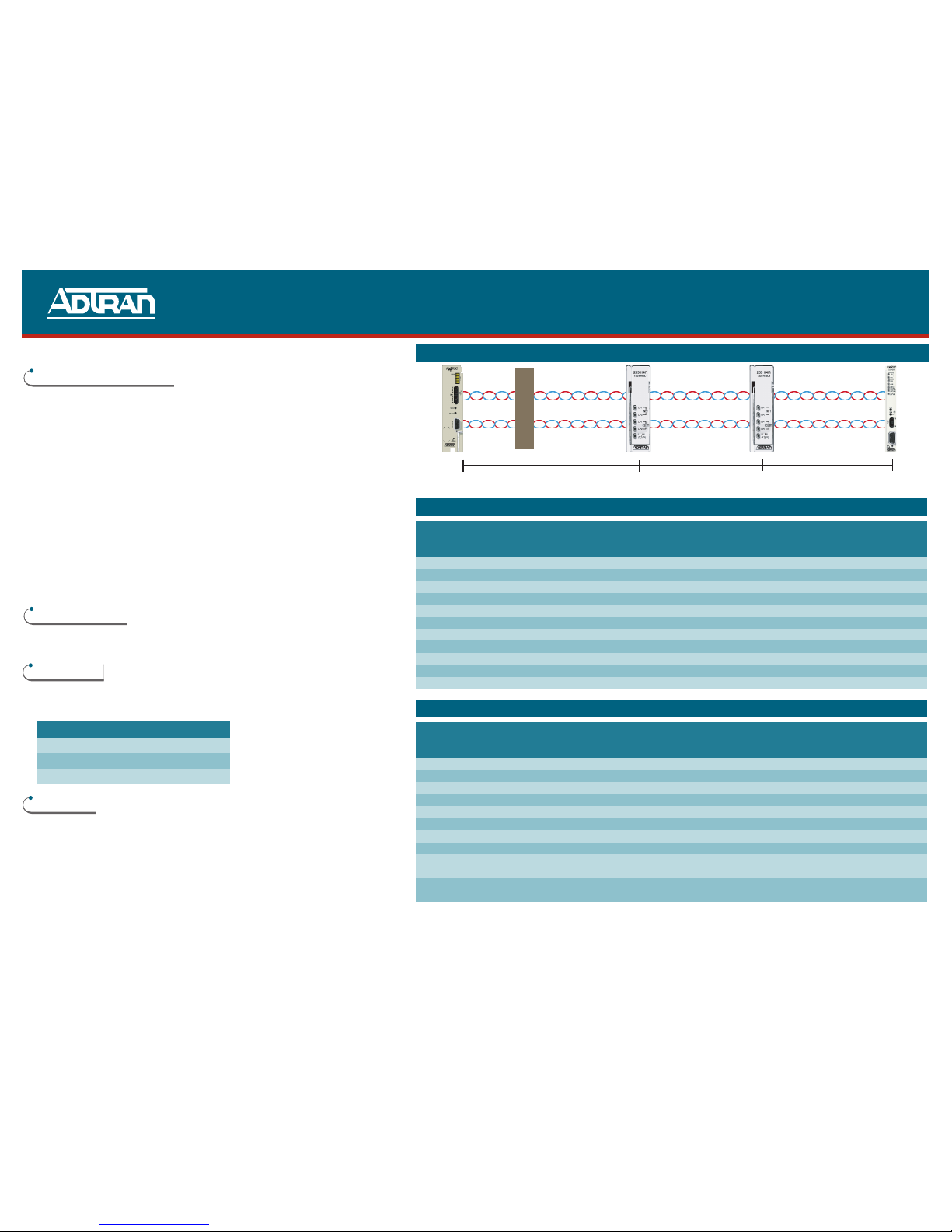
■HDSL4 circuit containing no H4Rs will reach up to 16 kft on the local loop (24
AWG)
■HDSL4 circuit containing one H4R will reach up to 16 kft on the first segment and
15 kft on the second segment (24 AWG).
■HDSL4 circuit containing two H4Rs will reach to 13.5 kft on the first segment, 14 kft
on the second segment, and 15 kft on the third segment (24 AWG). *
NOTE: Refer to the H4TU-C or H4TU-R Installation and Maintenance Practice, Section HDSL4,
Deployment Guidelines, for other loop parameters including Insertion Loss, Pulse
Attenuation, and Resistance Budgets for span powering
*This is one example of a circuit with 2 H4Rs. Other loop length configurations are
possible in compliance with loop resistance restraints. Refer to the H4R Installation
and Maintenance Practice, Section HDSL4 Deployment Guidelines, for other loop
parameters including Insertion Loss, Pulse Attenuation, and Resistance Budgets for
span powering.
UNIT RESISTANCE
Measurements are with no power applied
The H4R Tip-to-Ring resistance is approximately 6 Ωfor each pair.
COMPLIANCE
This product complies with UL 60950, third edition. It is intended for
installation in restricted access locations only and in equipment with a Type “B” or
“E” installation code. Ensure chassis ground is properly connected.
WARRANTY
Warranty for Carrier Networks products manufactured by ADTRAN and supplied
under Buyer’s order for use in the U.S. is ten (10) years. For a complete copy of
ADTRAN’s U.S. and Canada Carrier Networks Equipment Warranty
(P/N 60000087-10): call (877) 457-5007, faxback Document 414.
H4TU-C VMDF H4R1 H4R2 H4TU-R
TURNUP & TROUBLESHOOTING GUIDE
PRICING AND AVAILABILITY 800.827.0807
TECHNICAL SUPPORT 800.726.8663
RETURN FOR REPAIR 256.963.8722
www.adtran.com
61221445L1-22B
239 H4R Capacity Guidelines for ADTRAN Housings
PART No. Description CLEI CODE Slot Stub H4R Capacity Material
Above Below
Ground Ground
1150027L1 239/439 Housing DDMOABA1MA 4 Air 4 4 Stainless/Poly
1150027L2 239/439 Housing DDMOBBA1MA 4 Gel 4 4 Stainless/Poly
1152010L3 239/439 Housing DDMOBAE1RA 2 Gel 2 2 Polymer
1152010L4 239/439 Housing DDMOAAE1RA 2 Air 2 2 Polymer
1150057L1 Universal Housing DDMODAO1RA 4 Air 4 4 Stainless Steel
1150057L2 Universal Housing DDMOCAO1RA 4 Gel 4 4 Stainless Steel
1150058L1 Universal Housing DDMOEEO1RA 8 Air 8 8 Stainless Steel
1150058L2 Universal Housing DDMOFE01RA 8 Gel 8 8 Stainless Steel
1190816L1 16-Slot BG Housing DDMOES0IRA 16 Air 16 16 Stainless Steel
1190816L2 16-Slot AG Housing DDMOFS0IRA 16 Gel 16 16 Stainless Steel
1190816L3 16-Slot AG Housing DDMOMS01RA 16 Air 16 16 Stainless Steel
239 H4R Capacity Guidelines for Other Housings
Manufacturer Description Manufacturer’s Part Number Slot Stub H4R Capacity Material
Above Below
Ground Ground
ADC Radiator II SPX-HRXC-30-AG-016GT 16 Air 16 16 Stainless Steel
ADC Radiator II SPX-HRXC-30-BG-016GT 16 Gel 16 16 Stainless Steel
ADC Radiator SPX-HRXC-30-B1 8 Air 8 8 Stainless Steel
Circa Telecom HDSL-12A 760005 12 Air 12 12 Polymer
Circa Telecom HDSL-12B 760006 12 Gel 12 12 Polymer
Arris Keptel®Inter Link™809 RF809A3-XXX or RF809B3-XXX 12 Gel 8 1N/A Polymer
Arris Keptel®Inter Link™818/819 RF819A1 or RF819A2 25 Air 12 216 3, 4 Polymer
Arris Keptel®Inter Link™818/819 RF819B1 or RF819B2 25 Gel 12 216 3, 4 Polymer
Arris Keptel®Inter Link™RF820AX or
820 Family RF820BX 2-8 Air Full Full Polymer
Arris Keptel®Inter Link™RF820AX or
820 Family RF820BX 2-8 Gel Full Full Polymer
1The recommended 8 slot assignments for above ground installation are as follows: 1, 3, 4, 6, 7, 9, 10, 12.
2The recommended 12 slot assignments for above ground installation are as follows: Chamber 1: 1, 4, 7, 8, 11, 14 and Chamber 2: 15, 17, 19, 20, 23, 25
3For 16 slot use, the ambient air temperature measured 1 ft away and parallel to the housing should not exceed 115ºF (46.1ºC).
4The recommended 16 slot assignments for below ground installation are as follows: Chamber 1: 1, 3, 5, 7, 8, 10, 12, 14 and Chamber 2: 15, 16, 18, 19, 20, 22,
24, 25
Code Input Output
Power Code (PC) C C
Telecommunication Code (TC) X X
Installation Code (IC) A –
First Segment Second Segment Third Segment