manuals.online logo
Brands
  1. Home
  2. •
  3. Brands
  4. •
  5. ADTRAN
  6. •
  7. Network Card
  8. •
  9. ADTRAN 3192 H2TU-C User manual

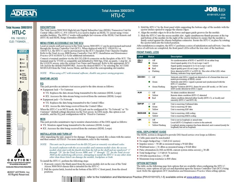
ADTRAN 3192 H2TU-C User manual

CAUTION!
SUBJECT TO ELECTROSTATIC DAMAGE
OR DECREASE IN RELIABILITY
HANDLING PRECAUTIONS REQUIRED
For more information, refer to the Installation and Maintenance Practice (P/N 61223004L4-5) available online at www.adtran.com.
©2014 ADTRAN, Inc.
All Rights Reserved.
HDSL2
3192 H2TU-C
P/N: 1223004L4
CLEI: T1I3AEYE_ _
HDSL2
3192 H2TU-C
ON-BOARD OPTIONS
The following options can be accessed on the circuit board:
Line Build Out (LBO) Switches
Use the DIP switch SW5 to select a distance of: 0-133 (default),
133-266, 266-399, or 399-533 feet.
Card Edge Pinouts
* The HDSL2 Loop is full duplex, capable of simultaneously sending and receiving data.
FRONT PANEL OPTIONS
The following options can be accessed on the front panel:
Pushbuttons
LBK To perform loopback functions, use the following methods:
To release the active loopback, press the LBK pushbutton until the ARM/LBK LED extinguishes.
LINE CODE Press this button to provision for AMI or B8ZS (default) line coding. A Green B8ZS LED
indicates B8ZS line code.
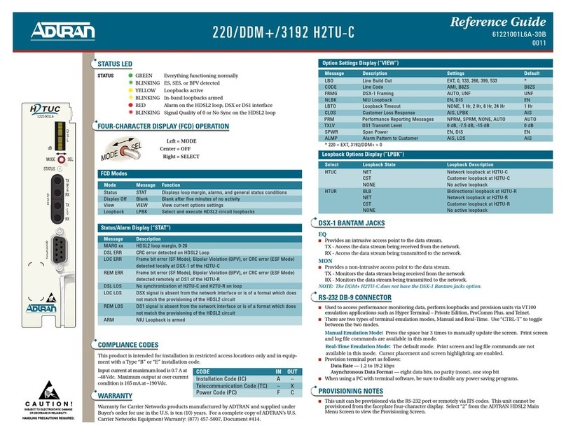
DSX EQ Splitting Jacks
TX DSX-1 transmit toward the local loop (intrusive)
RX DSX-1 receive from the local loop (intrusive)
DSX Monitor Jacks
TX DSX-1 transmit toward the local loop (nonintrusive)
RX DSX-1 receive from the local loop (nonintrusive)
RS-232 DB-9 Connector
Used to access performance monitoring data, perform loopbacks, and provision units via VT100 emulation
applications, such as HyperTerminal. There are two terminal emulation modes: Manual Update and Real-Time
Update. CTRL+T toggles between modes.
Manual Update Mode: Press the spacebar three times to manually update the screen. Print screen and log files
commands are available in this mode.
Real-Time Update Mode: The default mode. Print screen and log file commands not available. Cursor
placement and screen highlighting are enabled.
Provision terminal port for VT100: Data Rate = 1.2 to 19.2 kbps; Asynchronous Data Format = eight data
bits; no parity (none); one stop bit. When using a PC with terminal emulation software, be sure to disable any
power saving programs.
Pin # Function Pin # Function
1 R TX DSX (In from DSX) A T TX DSX (In from DSX)
2 R1 RX DSX (Out to DSX) B T1 RX DSX (Out to DSX)
5 GND H DCV LOS (to Alarm Module)
8 –48 V J Frame Ground
9 R HDSL2 Loop* K T HDSL2 Loop*
10 Fuse Alarm (to Alarm Module)
To Loop Up: Press and Hold LBK Button: ARM/LBK LED Shows:
H2TU-C Less than 3 seconds Green
H2TU-R More than 3 seconds Flashing Green
To Loop Down: Press and Hold LBK Button: ARM/LBK LED Shows:
H2TU-C Less than 3 seconds Off
H2TU-R Less than 3 seconds Off
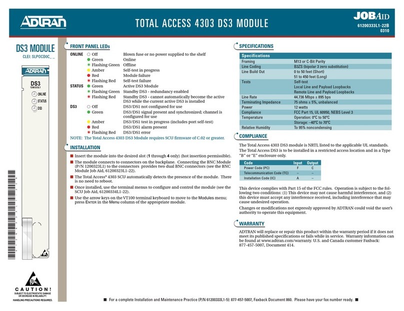
LED STATUS
COMPLIANCE
This product is intended for installation in restricted access locations only.
WARNING: Up to –200 VDC may be present on
telecommunications wiring.
CAUTION: The DSX-1 interface is intended for
connection to intra-building wiring
only. Ensure Chassis ground is
properly connected.
This product provides span powering voltage (negative only with respect to ground, –190 VDC nominal, GFI
protection < 5 mA) and meets all requirements of Bellcore GR-1089-CORE (Class A2), ANSI T1.418-2002.
This product is NRTL listed to the applicable UL standards.
HDSL2 LOOP GUIDELINES FOR OPTIMUM OPERATION
Cable pairs must be non-loaded
No single Bridged Tap > 2 kft.; Total Bridged Tap < 2.5 kft.
Loop Resistance:  
Attenuation: 30 dB
Impulse noise < 52 dBrnF (F filter)
Wideband noise < 47 dBrnF (F filter)
Margin 6 dB
Longitudinal Noise (Power Influence):
80 dBrnC: acceptable
80-90 dBrnC: marginal
> 90 dBrnC: unacceptable
Label Indications Description
STAT 
4

Off
Green Flashing
Green
Indicates a loss of power or blown fuse has occurred
Attempting to acquire HDSL2 synchronization with the H2TU-R
Normal operation; HDSL2 synchronization is achieved with the H2TU-R
DLOS 

Off
Red
DSX-1 signal is present and synchronized with no errors
No DSX-1 signal, or signal is present with errors
RLOS 

Off
Red
DS1 signal from CPE is present at H2TU-R with no errors
No DS1 signal from CPE at H2TU-R, or present with errors
HLOS 

4
Off
Red
Red Flashing
Normal Operation; end-to-end HDSL2 synchronization good
Loss of end-to-end HDSL2 synchronization on the 2-wire Loop
GFI or overcurrent condition detected
DSL 




Off
Green
Yellow
Red
Flashing
HDSL2 synchronization has not been achieved on the 2-wire Loop
Normal operation; signal margin is optimum (6 dB) on the 2-wire Loop
Marginal operation; signal margin is 1-5 dB on the 2-wire Loop
Margin dB; severely impaired HDSL2 operation
If attenuation (LOSS on Current System Status Screen) is 30 dB the DSL LED remains
solid. If attenuation is > 30 dB, the DSL LED flashes green, yellow, or red as determined by
the signal quality
HCRC 
4

Off
Yellow Flashing
Yellow
Normal operation; No HDSL2 CRC errors detected by this unit within the last 30 minutes
on the 2-wire Loop
One or more HDSL2 CRC errors are being detected by this unit on the 2-wire Loop
Four or more HDSL2 CRC errors have been detected on the 2-wire Loop within the last 30
minutes. The LED remains lit for 30 minutes. If no HDSL2 CRC errors occur within a 
rolling 30 minute interval, the LED extinguishes.
ARM/
LBK



4
Off
Yellow
Green
Green Flashing
Unit is not in the armed or loopback state
Unit is an armed state
A loopback is active on this specific unit
A loopback is active on the H2TU-R
B8ZS 

Off
Green
Unit is receiving AMI line code
Unit is receiving B8ZS line code
Configuration Code Input Output
Power Code F C
Telecommunication Code (TC) – X
Installation Code (IC) A –
O
N
1
O
N
13
3
O
N
13
ON
DSX-1 LBO
0
133
266
ON
ON
ON
ON
ON
OFF
ON
OFF
ON
399
533
ON
OFF
OFF
ON
OFF
ON
2
2
2
1223004L4
STAT
TX
RX
TX
RX
DSX MON
DSX EQ
DLOS
RLOS
HLOS
DSL
HCRC
ARM
/LBK
(Y)
(G)
B8ZS
LINE
CODE
LBK
*61223004L4-22G*
Issue Date: January 2014
Document P/N: 61223004L4-22G
PRICING AND AVAILABILITY 800.827.0807
TECH SUPPORT 800.726.8663
RETURN FOR REPAIR 256.963.8722
www.adtran.com
61223004L4-22G
Warranty: ADTRAN will replace or repair this product within the warranty period if it does not meet its published specifications or fails while in service. 
Warranty information can be found online at www.adtran.com/warranty.
TROUBLESHOOTING HDSL2
This ADTRAN HDSL2 unit is equipped with troubleshooting-at-a-glance LEDs (identified on the reverse side of this document)
that provide a simple means of identifying the location of certain faults. Additionally, screens available via the craft interface
simplify the trouble isolation process. These screens and their associated benefits are described below.
Troubleshooting Screen
The Troubleshooting screen, available via the Main Menu, provides both current and 7-day historical view of performance. Errors
and/or alarms detected at any of the monitored inputs (DSX-1, DS1 and HDSL) will be displayed in tabular format and highlighted
in reverse video. This screen automatically escalates the error/alarm conditions using reverse video display. Faults detected and their
associated meanings are as follows:
DSL:
LOS Loss of HDSL sync
MARG Margin has exceeded the alarm threshold
ATTEN Attenuation has exceeded the alarm threshold
ERR Errors recorded at the HDSL receiver
Facility:
GROUND Ground Fault Interrupt on span voltage (facility pair grounded)
SHORT Short circuit (or low impedance) between facility pairs
OPEN Open circuit between facility pairs
DSX-1/DS1:
LOS Loss of signal (Red Alarm) at the DSX-1/DS1 receiver
CLK T1 receive clock is out of range
RAI Remote Alarm Indication (Yellow Alarm) detected at DSX-1/DS1 receiver
AIS Alarm Indication Signal (Blue Alarm) detected at DSX-1/DS1 receiver
ERR Errors recorded at DSX-1/DS1 receiver
Troubleshooting Guidance Screens
The Troubleshooting Guidance screens, available via the Troubleshooting screen, provide guidance on the fault(s) detected. The
screens also provide the possible cause(s) and suggested corrective actions that can be taken.
Along with the Troubleshooting screens, the Detailed Status screen and Performance History screen, available via the craft access
terminal, provide both real-time and historical view of this circuit.
FEATURES
TScan 2.0
This module incorporates the TScan 2.0™feature. TScan allows for remote retrieval of circuit diagnostics and performs advanced
fault location. For more information about TScan refer to the Installation and Maintenance practice.
Bad Splice Detection
The Runtime TScan splice detection feature is an ADTRAN proprietary non-intrusive method for detection of anomalies (bad
splices) in the copper plant.
Data transmission transceivers, especially echo-cancelled technologies, such as HDSL2 (or HDSL4) are subject to degraded
performance in the presence of bad splices. Poor splices in the cable are often undetected by normal testing methods. Often, these
splices present no problem for the data transmission equipment until the point at which oxidation with the splice itself causes a rapid
impedance change. Such a change in impedance may cause errors, signal margin fluctuation, and/or a retrain of the DSL
transceivers. To address the difficulty in identifying bad splices, ADTRAN has developed the splice detection feature. This feature
non-intrusively monitors the cable pair during runtime for the presence of bad splices, which may potentially impact service.
Fault Bridging
Fault Bridging is a feature that minimizes downtime due to an intermittent impairment (GFI, short, micro-interruption, bad splice,
noise burst, etc.) that appears on the cable pair.
The bridging feature allows the DSL transceivers to maintain synchronization during such an interruption, thus avoiding a 25 to 30
second retrain. Depending on the type of impairment, interruptions as long in duration as 200 ms can be bridged.
Fast Retrain
Fast Retrain is an ADTRAN proprietary feature that minimizes downtime due to an intermittent impairment (bad splice, noise burst,
etc.) which due to its duration cannot be bridged.
When such impairments occur after HDSL synchronization has been achieved, the fast retrain feature will be invoked to restore
service within 5 to 7 seconds. This short retrain time allows for reduced downtime compared to the traditional 25 to 30 second
retrain duration.
NOTE: Fast-Retrain capable units must be installed on both ends of the HDSL2 circuit for this feature to function properly. Also, if there is a failure of a
fast retrain attempt, for any reason, then the traditional (25-30 second) retrain will be initiated.
LOOPBACK AND CONTROL CODES
1 Units must be armed with 11000b or FF48h before this code can work.
2 This code will be detected only if the units are armed and there are no loopbacks active.
NOTE: All codes listed above must be sent for a minimum of five seconds in order to be detected and acted upon.
NOTE: If NIU is enabled, then the H2TU-R can be in network loopback when the H2TU-C loop-up codes are sent.
Function Code (Hex / Bin) Response
ARM (in-band)
a.k.a. 2-in-5 pattern
11000 When sent from the network, the units arm and the H2TU-R loops up, if NIU Loopback
is enabled. When sent from the customer, the units arm.
ARM
(ESF Data Link)
FF48 or
1111 1111 0100 1000
sent via
Facility Data Link (FDL)
When sent from the network, the units arm and the H2TU-R loops up, if NIU Loopback
is enabled. When sent from the customer, the units arm.
Disarm (in-band)
a.k.a. 3-in-5 pattern
11100 When sent from the network or customer, all units are removed from the armed state and
loopbacks are released
Disarm
(ESF Data Link)
FF24 or
1111 1111 0010 0100
(FDL)
When sent from the network or customer, all units are removed from the armed state and
loopbacks are released.
H2TU-C Network
Loopback1
D3D3 or
1101 0011 1101 0011
If armed, the H2TU-C loops toward the network, 2 seconds of AIS (all 1s) is transmitted,
the looped data is sent for 5 seconds, and a burst of 231 logic errors is injected. The burst
of 231 logic errors continues every 20 seconds as long as the D3D3 pattern is detected.
When the pattern is removed, the unit remains in loopback. If the pattern is re-instated,
the injection of 231 logic errors continues every 20 seconds. If the pattern is sent from
the network, the loop up and error injection is toward the network. If the pattern is sent
from the customer, the loopback and error injection will be toward the customer
H2TU-R Customer
Loopback1
3F02 or
0011 1111 0000 0010
When sent from the network, if the units are armed, the H2TU-R loops up data from the
customer toward the customer
Loopdown
w/o disarm
9393 or
1001 0011 1001 0011
When sent from the network or customer, all units currently in loopback loop down.
Armed units do not disarm. In order to behave like a smartjack, the H2TU-R does not
loop down from a network loopback in response to the 9393 pattern if NIU Loopback is
enabled. In order to behave like an NIU, the H2TU-R will not loop down from the net-
work side with 9393h.
Loopback Query1D5D5 or
1101 0101 1101 0101
This pattern allows a query of the devices to determine whether any units are in loop-
back. If D5D5 hex is received while in a loopback state, the unit in question transmits a
logic error count. When sent from the network, logic errors are injected towards the net-
work to indicate a loopback is present toward the network as follows: 231 bit errors every
20 seconds if an H2TU-C; 200 bit errors every 10 seconds if an H2TU-R. When sent
from the customer, 200 bit errors will be injected toward the customer every 20 seconds
if an H2TU-R is in customer loopback.
Loopback Time Out
Override1, 2
D5D6 or
1101 0101 1101 0110
When sent from the network or customer, if the units are armed or a unit is currently in
loopback, the loopback timeout override is disabled, and loopbacks do not time out
(regardless of the current loopback timeout setting). As long as the units remain armed,
the timeout remains disabled. When the units are disarmed, the loopback timeout reverts
to the previous setting.
Span Power
Disable1, 2
6767 or
0110 0111 0110 0111
When sent from the network or customer, if the units are armed, span power is disabled.
When sent from the network, the span power is disabled as long as the pattern is detected.
Once the pattern is no longer being received, the H2TU-C reactivates span power. All
units then re-train and return to the disarmed and unlooped state. When sent from the
customer, span power is only disabled momentarily.
Query Loop
Parameters1
DBDB or
1101 1011 1101 1011
If the H2TU-C is in network loopback, errors are injected into the DSX-1 signal, and
repeated every 20 seconds. The number of errors injected each time depends on the cur-
rent status of signal margin and pulse attenuation parameters on each loop. 111 errors are
injected if all HDSL2 receiver points (H2TU-C, H2R, NET LP, H2R CST, and H2TU-R
LP) indicate pulse attenuation is 30 and signal margin is 6 dB. 11 errors at a time are
injected if any of the receiver points indicate pulse attenuation is > 30 dB and/or signal
margin is < 6 dB.
H2TU-R Address 20
for extended
demarc.
C754 or
1100 0111 0101 0100
If armed the H2TU-R loops up, 2 seconds of AIS (all 1s) is transmitted, the looped data is
sent for 5 seconds, and then a burst of 200 logic errors is injected. The burst of 200 logic
errors continues every 10 seconds as long as the C754 pattern is detected from network
(20 seconds if from customer). When the pattern is removed, the unit remains in loop-
back. If the pattern is re-instated, the injection of 200 logic errors continues. If the pattern
is sent from the network, the loopup and error injection is toward the network. If the pat-
tern is sent from the customer, the loopback and error injection is toward the customer.
HDSL2
3192 H2TU-C
Other manuals for 3192 H2TU-C
3

This manual suits for next models

1

Other ADTRAN Network Card manuals

ADTRAN 5000 Series Operating manual

ADTRAN

ADTRAN 5000 Series Operating manual

ADTRAN AHT1U User manual

ADTRAN

ADTRAN AHT1U User manual

ADTRAN DDM+ H2TU-C Instruction Manual

ADTRAN

ADTRAN DDM+ H2TU-C Instruction Manual

ADTRAN NetVanta 8044M User manual

ADTRAN

ADTRAN NetVanta 8044M User manual

ADTRAN NetVanta 1000R Series Operating manual

ADTRAN

ADTRAN NetVanta 1000R Series Operating manual

ADTRAN TRACER 6000 SERIES User guide

ADTRAN

ADTRAN TRACER 6000 SERIES User guide

ADTRAN TRACER Protection Switch User manual

ADTRAN

ADTRAN TRACER Protection Switch User manual

ADTRAN DS3 User manual

ADTRAN

ADTRAN DS3 User manual

ADTRAN 239 T1 HDSL4 Instruction Manual

ADTRAN

ADTRAN 239 T1 HDSL4 Instruction Manual

ADTRAN 3192 H4TU-C User manual

ADTRAN

ADTRAN 3192 H4TU-C User manual

ADTRAN 20 Ohm Adapter User manual

ADTRAN

ADTRAN 20 Ohm Adapter User manual

ADTRAN Type 400 Instruction Manual

ADTRAN

ADTRAN Type 400 Instruction Manual

ADTRAN 3192 H2TU-C User manual

ADTRAN

ADTRAN 3192 H2TU-C User manual
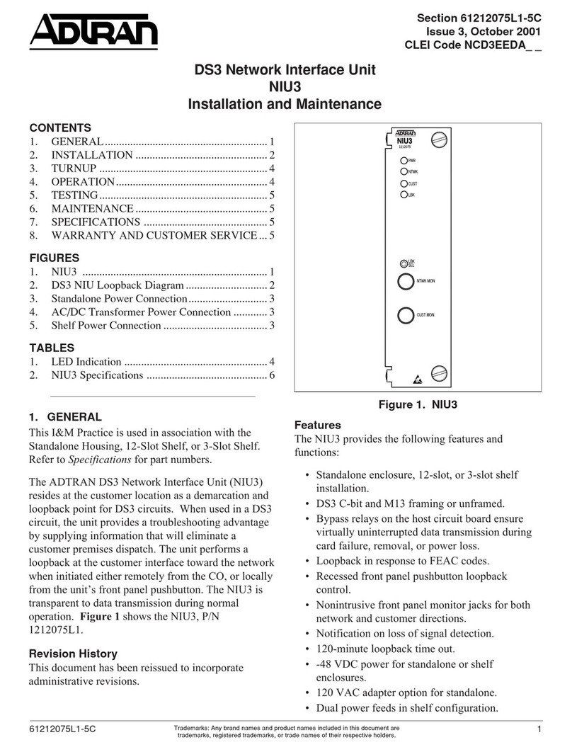
ADTRAN NIU3 Instruction Manual

ADTRAN

ADTRAN NIU3 Instruction Manual

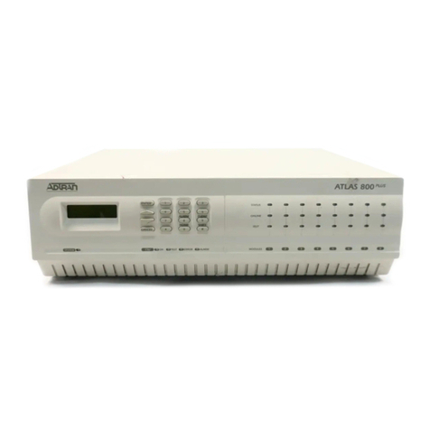
ADTRAN ATLAS 800 Series Module QUAD E1 User manual

ADTRAN

ADTRAN ATLAS 800 Series Module QUAD E1 User manual

ADTRAN OPTI-6100 LMX User manual

ADTRAN

ADTRAN OPTI-6100 LMX User manual

ADTRAN 900 Series User manual

ADTRAN

ADTRAN 900 Series User manual

ADTRAN 3000 HTU-C User manual
ADTRAN

ADTRAN 3000 HTU-C User manual
ADTRAN 3.125 Gigabit Ethernet User manual

ADTRAN

ADTRAN 3.125 Gigabit Ethernet User manual

ADTRAN 850 DSX-1 User manual

ADTRAN

ADTRAN 850 DSX-1 User manual

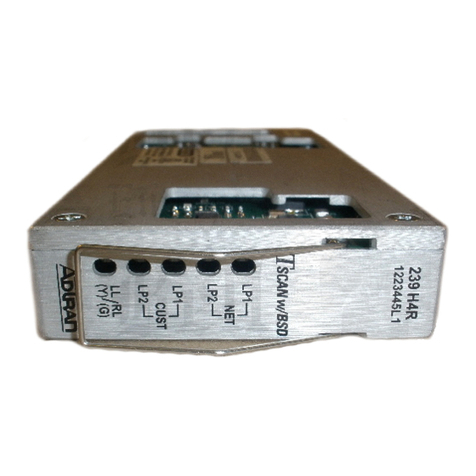
ADTRAN 239 H4R User manual

ADTRAN

ADTRAN 239 H4R User manual

ADTRAN ATLAS 800 Series Module Nx56/64 Bonding User manual

ADTRAN

ADTRAN ATLAS 800 Series Module Nx56/64 Bonding User manual

ADTRAN TOTAL ACCESS OPTI-T200 User manual

ADTRAN

ADTRAN TOTAL ACCESS OPTI-T200 User manual

ADTRAN 3000 NTU-8 Instruction Manual

ADTRAN

ADTRAN 3000 NTU-8 Instruction Manual

Popular Network Card manuals by other brands

TP-Link TL-PA4020 Quick installation guide

TP-Link

TP-Link TL-PA4020 Quick installation guide

Cisco IDTA153 installation manual

Cisco

Cisco IDTA153 installation manual

NETGEAR DG814 - DSL Modem Internet Gateway Reference manual

NETGEAR

NETGEAR DG814 - DSL Modem Internet Gateway Reference manual

TRENDnet TEW-642EC Quick installation guide
TRENDnet

TRENDnet TEW-642EC Quick installation guide

Dynex DX-NNBC - N NOTEBOOK CARD WiFi user guide

Dynex

Dynex DX-NNBC - N NOTEBOOK CARD WiFi user guide

SyChip WLAN6065SD user manual

SyChip

SyChip WLAN6065SD user manual

PC LINE PCL-PCI10 quick start guide

PC LINE

PC LINE PCL-PCI10 quick start guide

NexWatch PW-5000 PW5K1EN installation manual

NexWatch

NexWatch PW-5000 PW5K1EN installation manual

National Instruments NI 9478 operating instructions

National Instruments

National Instruments NI 9478 operating instructions

Allwins AWU50G-W user manual

Allwins

Allwins AWU50G-W user manual

Dynex DX-NNBC - N NOTEBOOK CARD WiFi Quick install guide

Dynex

Dynex DX-NNBC - N NOTEBOOK CARD WiFi Quick install guide

Gtran Wireless DotSurfer GPC-2100 user manual

Gtran Wireless

Gtran Wireless DotSurfer GPC-2100 user manual

Sierra Wireless AirCard 880 Wireless Modem quick start guide

Sierra Wireless

Sierra Wireless AirCard 880 Wireless Modem quick start guide

CSL 300149 user manual

CSL

CSL 300149 user manual

Sonnet PRESTO GIGABIT quick start guide

Sonnet

Sonnet PRESTO GIGABIT quick start guide

ICP DAS USA ZT-2018/S quick start

ICP DAS USA

ICP DAS USA ZT-2018/S quick start

Hawking HGU1 Quick installation guide

Hawking

Hawking HGU1 Quick installation guide

3Com 3C589D user guide

3Com

3Com 3C589D user guide

manuals.online logo
manuals.online logoBrands
  • About & Mission
  • Contact us
  • Privacy Policy
  • Terms and Conditions

Copyright 2025 Manuals.Online. All Rights Reserved.