manuals.online logo
Brands
  1. Home
  2. •
  3. Brands
  4. •
  5. ADTRAN
  6. •
  7. Network Hardware
  8. •
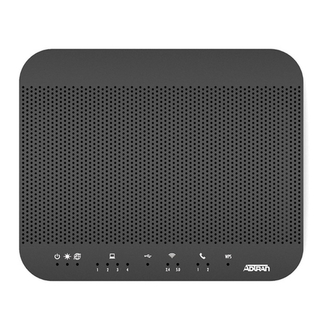
  9. ADTRAN 602 User manual

ADTRAN 602 User manual

Q
uic
k
Start
DESCRIPTION
The ADTRAN 602 Next Generation Passive Optical Network (NG-PON2)
Optical Network Termination (ONT) provides one, 10 Gigabit symmetrical
PON interface.
NG-PON2 TECHNOLOGY
NG-PON2 is a telecommunication standard for passive optical networks
(PONs). This standard details a network architecture of 10 Gbps upstream
and downstream speeds available to each subscriber.
NG-PON2 is compatible with existing PON fiber by simply replacing the
OLT at the central office and the ONT at each end user.
NG-PON2 uses time and TWDM to multiplex a number of optical signals
onto a single fiber for both upstream and downstream wavelengths.
NG-PON2 supports fixed wavelength XGS-PON optics when one of the
following ADTRAN SFPs are used as the network interface:
■SFP+ 10G 1270 Tx/1577 Rx (P/N: 1200488F1C)
■SFP+ 10G 1310 Tx/1490 Rx (P/N: 1200488F2C)
FEATURES
The basic features of the ADTRAN 602 include the following:
■Single fiber 10 Gbps symmetric operation
■IPTV Support
■Operational Standards
♦MAC Forwarding
♦Remote activation and deactivation
♦Remote software upgrades
♦OMCI G.988 Management Support
♦Auto Discovery
♦Reset Function
■Optical Standards
♦Meets all applicable requirement of ITU-T G.989.x Specifications
■Meets all applicable domestic and international compliance
requirements, including the following:
♦UL/CUL 60950-1
♦IEC 60950-1/EN 60950-1/AS/NZS 60950.1
♦RoHS
♦FCC Part 15 Class B
♦IEEE 802.3
FRONT PANEL CONNECTIONS
The following table describes the connections on the front panel.
INSTALLATION
Before installing the ADTRAN 602, inspect it for damage. If damage has
occurred during shipping, file a claim with the carrier and then contact
ADTRAN. For more information, refer to the warranty.
Installation Guidelines
The following are guidelines for this installation.
fWARNING!
Read all warnings and cautions before installing or servicing the ADTRAN
602.
Installation Overview
To install the ADTRAN 602, you will need to complete the following steps:
■“Step 1: Locate the ADTRAN 602”
■“Step 2: Ground the ADTRAN 602”
■“Step 3: Clean the LAN or WAN Connections”
■“Step 4: Install SFP+ or XFP”
■“Step 5: Connect Power”
■“Step 6: Connect UPS (Optional)”
Required tools
Standard technician tools and those listed below are required for installing
the ADTRAN 602.
■PON power meter with wavelength filtering
■Fiberscope or videoscope
Connection Description
POWER Power connection for the supplied AC to DC power con-
verter
UPS 12 VDC uninterruptible power supply (UPS) and alarm con-
nection
GE 1 GigE, RJ45 customer LAN connection
LAN 10 GigE SFP customer LAN connection
SFP+WAN 10 Gig PON SFP+ connection
XFP WAN 10 Gig PON XFP connection
ADTRAN
602
Multi-10G/10G Universal ONT
October 2016
61287800F1-13A
P/N: 1287800F1
POWER UPS GE LAN SFP+WAN XFP WAN
POWER
WAN
LAN
RESET
12V
602 10G ONT
Chassis
Ground
2 61287800F1-13A
2. Select the appropriate mounting bracket and using the holes in the
mounting brackets as a template, mark the surface where the
screws will attach the ADTRAN 602 to the plywood surface.
3. Secure the brackets to the sides of the ADTRAN 602 using the
screws provided.
4. Secure the ADTRAN 602 to the plywood using two #6 to #10 wood
screws, at least 3/4” in length.
Step 2: Ground the ADTRAN 602
To ground the ADTRAN 602, refer to the illustration on the first page and
complete the following steps:
1. Attach a minimum 18 AWG ground strap to the Chassis Ground
using a UL approved ring lug and anti-rotational device (star
washer).
2. Tighten the ground strap using the 1/4 inch nut supplied with the
ADTRAN 602.
3. Connect the other end of the ground strap to a known, reliable
ground at the installation site/location.
4. Using an ohmmeter, verify continuity between the ground lug and
known good frame ground. The reading should be less than 1 ohm.
Step 3: Clean the LAN or WAN Connections
To clean the Customer LAN or WAN connections for the ADTRAN 602,
refer to the illustration on the first page and complete the following steps:
1. Clean Optical interfaces of the appropriate SFP+/XFP.
f
CAUTION!
■Do not allow disconnected optical connectors to touch surrounding
unrelated surfaces and do not touch optical surfaces for any reason
other than while performing the cleaning process.
■Do not use compressed air to clean optical connectors.
■Clean the optical surfaces as follows:
♦Use a fiberscope or videoscope to verify proper cleaning of
connectors prior to connecting components together.
♦Use pure alcohol (reagent grade, 99.5% pure) when cleaning the
endface of connectors. The alcohol can be applied with either
laboratory grade lint-free tissues or with pre-moistened optical
grade wipes.
♦Use microporous fabric spiral wrapped cleaning tips to clean
bulkhead ferrules.
gNOTE
The following are guidelines for installing the SFP/XFP:
■The latch on the SFP/XFP is for removal only. When removing the
SFP/XFP, rotate the latch away from the SFP/XFP cage until a
physical click occurs. The SFP/XFP should slide easily out of the cage.
■Always have dust caps and dust plugs installed when connectors or
adapters are not mated. Store dust caps in a sealable plastic bag
when not in use.
Step 4: Install SFP+ or XFP
To install the SFP+ or XFP, complete the following steps:
1. Insert the appropriate SFP+ or XFP into the appropriate cage with
the latch handle facing outward. Slide the SFP+ or XFP all the way
into the SFP cage.
2. Using thumb and forefinger, exert adequate pressure to ensure the
SFP+ or XFP is completely seated in the cage.
■Phillips-head screw driver
■Assorted tie wraps for securing cabling and wiring
For fiber optic connections, the following are required:
■Fiber optical fusion splice tools
■ODC Fiber cleaning tool
■SC/UPC Fiber connector
Installation Steps
To install the ADTRAN 602, complete the following steps.
Step 1: Locate the ADTRAN 602
There are three options to install the ADTRAN 602: Desk Top, Rack
Mount, and Wall Mount. All options are described below.
gNOTE
Included with the ADTRAN 602 is a 4-foot power cord. All installation
locations should be within 4-feet of a wall outlet.
Desk Top Installation
The ADTRAN 602 can be located on a desktop.
fWARNING!
Ensure that the ADTRAN 602 does not come in contact with water or other
liquids.
f
CAUTION!
Ensure that the ADTRAN 602 is not located in direct sunlight or next to
any thermal obstructions.
Rack Mount Installation
Refer to Figure 1 and perform the following steps:
1. Select the appropriate mounting bracket and secure it to the side of
the ADTRAN 602 in the orientation desired using the screws pro-
vided.
2. Secure the ADTRAN 602 to a rack using the appropriate mounting
screws.
Figure 1. Attach Mounting Brackets
Wall Mount
Refer to Figure 1 and perform the following steps:
1. Prepare the mounting surface by attaching a board (typically ply-
wood, 1/4” to 1/2” thick) to the wall studs using appropriate lag bolts.
Mounting Bracket
(P/N: 3265479-2E@E)
Mounting Bracket
(P/N: 3265937-1E@C)
61287800F1-13A 3
3. Attach one end of the cable to the SFP+WAN or XFP WAN port on
the front of the ADTRAN 602.
Step 5: Connect Power
To connect power to the ADTRAN 602, complete the following steps:
1. Plug the supplied 12V AC/DC Power Converter into the POWER
connection on the front of the ADTRAN 602.
2. Connect the Power Converter to a standard 100-240V AC outlet.
3. Verify the power is on by checking the POWER LED on the
ADTRAN 602. The LED should be green indicating local power is
on.
Step 6: Connect UPS (Optional)
The UPS must be UL Listed, and have a LPS with an output rated at 12
VDC minimum 3.0 Amps and suitable for the intended location.
The UPS connection on the front of the ADTRAN 602 is used to connect a
commercial UPS Battery backup unit. To connect the USP backup power
supply, complete the following steps:
1. Connect the power cord from the UPS Battery backup unit to the
UPS connection on the front of ADTRAN 602.
2. Connect the UPS Battery backup unit to a regular 100-240 VAC
outlet.
FRONT PANEL LEDS
When the ADTRAN 602 first powers up it performs self-tests. Once the
power up self-tests are complete, the status LEDs will reflect the true
state of the hardware.
Resetting the ONT
wNOTICE
Resetting the ONT returns all settings to their factory defaults. Regis-
tration provisioning will be lost.
A reset button is available if the ADTRAN 602 needs to be rebooted. To
reset the ADTRAN 602, press the RESET button for 5 seconds or longer.
ACRONYMS
AWG American Wire Gauge
GE Gigabit Ethernet
LAN Local Area Network
LED Light Emitting Diode
LPS Local Power Supply
Label Status Indication
POWER 

Off
ON
Power is off
Power is on
WAN 

2


Off
Yellow
Yellow Flashing
Green
Red
No light detected from OLT
ONT detects light from OLT
Ranging in process
ONT is ranged and up
ONT discovered, but not active
LAN 

2

2

Off
Green
Green Flashing
Yellow
Yellow Flashing
Red
LAN is down
10G link is up
Data transfer in process
Data rate is out of range
Data transfer in process
Port is Administratively up, Link is
down
NG-PON Next Generation Passive Optical Network
ODC Optical Directional Coupler
OMCI OpenManageTM Client Instrumentation
ONT Optical Network Terminal
PON Passive Optical Network
SC/UPC Standard Connector/Ultra Physical Contact
SFP Small Form-factor Pluggable
UPS Uninterruptible Power Supply
TWDM Time and Wavelength Division Multiplexing
WAN Wide Area Network
XFP 10G Form-factor Pluggable
XGSPON Ten Gigabits Passive Optical Network
Operational Specifications
■Electrical
♦Operating Voltage: 12 VDC
♦AC to DC Power Supply: 100 to 240 VAC, 50 to 60 Hz
♦Power Consumption: Typical 25 watts
■Physical
♦8.0 inches wide (20.0 centimeters)
♦8.0 inches deep (20.0 centimeters)
♦1.75 inches high (4.5 centimeters)
♦Weight: 2 pounds (0.9 kilograms)
■Environmental
♦Operational Temperature: –5°C to +50°C (+23°F to 122°F)
♦Storage Temperature: –2°C to +85°C (+28°F to 185°F)
♦Relative Humidity: 90%, noncondensing
MAINTENANCE
The ADTRAN 602 does not require routine hardware maintenance for
normal operation. ADTRAN does not recommend that repairs be
attempted in the field. Repair services may be obtained by returning the
defective unit to ADTRAN. Refer to the warranty for further information.
Field support for software is provided through upgrade facilities.
SAFETY AND REGULATORY
fWARNING!
■Read all warnings and cautions before installing or servicing this
equipment.
■Refer to the national, state and local electrical codes for the
requirements for power and grounding wiring methods.
■The Gigabit Ethernet port(s) are classified as Type 4a, as defined in
Appendix B of GR-1089-CORE, and is/are suitable for connection to
intra-building, unexposed, wiring or cabling only. Do not metallically
connect the Gigabit Ethernet port(s) to interfaces which connect to
exposed or Outside Plant (OSP) wiring or cabling. The Gigabit
Ethernet port(s) is/are designed for use as intra-building interface(s)
only (4a ports as described in GR-1089-CORE) and requires isolation
from exposed OSP cabling. The addition of Primary Protectors is not
sufficient protection in order to connect the interface metallically to
OSP wiring.
CCAUTION!
■This product contains or uses a Class 1 Laser module that complies
with FDA 21 CFR 1040.10, 1040.11 and IEC 60825-1. For continued
compliance with the above standards, only approved Class 1 laser
modules from an ADTRAN approved vendor list (located on the
CAUTION!
SUBJECT TO ELECTROSTATIC DAMAGE
OR DECREASE IN RELIABILITY
HANDLING PRECAUTIONS REQUIRED
Warranty: ADTRAN will replace or repair this product within the warranty period if it does not
meet its published specifications or fails while in service. Warranty information can be
found online at www.adtran.com/warranty.
Trademarks: Brand names and product names included in this document are trademarks,
registered trademarks, or trade names of their respective holders.
©2016 ADTRAN, Inc. All Rights Reserved.
ADTRAN CUSTOMER CARE:
From within the U.S. 1.888.423.8726
From outside the U.S. +1 256.963.8716
PRICING AND AVAILABILITY 1.800.827.0807
*61287800F1-13A*
ADTRAN website) should be installed in this product. ADTRAN cannot
certify system integrity with other laser modules.
f
CAUTION!
■The chassis frame ground terminal must be connected to an earth
ground to ensure that the exposed metal on the product is properly
grounded.
■This equipment contains no parts that can be serviced by the user.
■An external AC Surge Protection Device must be installed at the AC
input connection to the local AC-Powered product. The Surge
Protection device should provide L-N, L-G, and N-G protection. It is
also recommended that the device contains a visual 'GOOD' indicator.
gNOTE
■This device complies with Part 15 of the FCC rules. Operation is
subject to the following two conditions:
♦This device may not cause harmful interference.
♦This device must accept any interference received, including inter-
ference that may cause undesired operation.
■Changes or modifications not expressly approved by ADTRAN could
void the user’s authority to operate this equipment.
■This product is intended to be installed and serviced by qualified
Service Personnel only.
■This product has been evaluated to international safety standards EN
60950-1, AS/NZS 60950.1, and IEC 60950-1.
■This product is designed to operate with a nominal operating voltage
of 12 VDC.
■This product is designed to be deployed in GR-3108-CORE
environmental Class 1.
■This product is intended for deployment in CO-type Facilities, EECs
and locations where the NEC applies (ex. Customer Premises).
■The product contains a power adapter, which operates from a main
power source input of 100 - 240 V, 50/60 Hz, with a nominal output of
12 VDC.
■This product is NRTL Listed to the applicable UL Standards.
■This product meets the requirements for CE marking under the EMC
Directive, and Low Voltage Directive. Standards used to demonstrate
Compliance are EN 300 386 and EN 60950.
■This product meets EU RoHS Directive. Refer to www.adtran.com for
further information on RoHS/WEEE.
FRANÇAIS
fAVERTISSMENT!
■Lisez tous les avertissements et mises en garde avant l’installation de
cet équipement ou la réalisation de toute opération de maintenance.
■Consultez les normes nationales, régionales et locales sur les
installations électriques pour connaître les exigences en matière de
câblage pour l’alimentation et la mise à la terre.
C
ATTENTION!
Ce produit contient ou utilise un module laser de classe 1 qui est
conforme à la FDA 21 CFR 1040.10, 1040.11 et IEC 60825-1. Pour
maintenir la conformité avec les normes ci-dessus, seulement approuvés
laser de classe 1 modules à partir d'une liste approuvée de ADTRAN
fournisseur (situé sur le site ADTRAN) doit être installé dans ce produit.
ADTRAN ne peut certifier l'intégrité du système avec d'autres modules
laser.
fATTENTION!
■La borne de mise à la terre du châssis doit être branchée à une prise
de terre afin d’assurer que le boîtier métallique de la SFP est
correctement mis à la terre grâce au connecteur de face arrière.
■Il n’existe aucune pièce pouvant être réparée par l’utilisateur à
l’intérieur de cet équipement.
■Un Dispositif de protection contre les surtensions CA externe doit être
installé à la connexion d'entrée AC au produit AC-Powered locale. Le
dispositif de Protection contre les surtensions devrait fournir L-N, L-G
et la protection de la N-G. Il est également recommandé que le
dispositif incorpore un indicateur visuel de « Bon ».
gREMARQUE
■Les changements ou modifications non expressément approuvés par
ADTRAN pourraient annuler l'autorisation de l'utilisateur d’utiliser cet
équipement.
■Installation du produit dans un emplacement à accès restreint. Ce
produit a été conçu pour être installé et entretenu exclusivement par
un personnel de service qualifié.
■Ce produit a été conçu pour répondre aux normes internationales de
sécurité EN 60950-1, AS / NZS 60950,1 et IEC 60950-1.
■Ce produit est conçu pour fonctionner avec une tension nominale de
fonctionnement de 12 VDC.
■Le produit contient un adaptateur d'alimentation, qui fonctionne à
partir d'une entrée principale source d'alimentation de 100 - 240 V, 50/
60 Hz, avec une puissance nominale de 12 VDC.
■Ce produit répond aux exigences de marquage CE et toutes les
directives applicables. Ce produit a été conçu pour répondre aux
exigences de la ETSI EN 300 386.
■Ce produit est conforme à la directive européenne RoHS. Reportez-
vous à www.adtran.com pour de plus amples renseignements sur
RoHS.
Documentation for ADTRAN Network Solutions products is available for
viewing and download directly from the ADTRAN Support Community
website.
Go to: https://supportforums.adtran.com/welcome
Registration is required.
ADTRAN offers training courses on our products, including customized
training and courses taught at our facilities or at customer sites.
For inquiries, go to: http://adtran.com/training
The following online documents and resources provide additional information for this product:
Carrier Ethernet CLI Dictionary
Carrier Ethernet Feature Guide
SFP/XFP/SFP+ Compatibility Matrix (Online Tool: www.adtran.com/SFP))

Other ADTRAN Network Hardware manuals

ADTRAN Dial Backup Interface Module 1204006L2 User manual

ADTRAN

ADTRAN Dial Backup Interface Module 1204006L2 User manual

ADTRAN Express 3100 User manual

ADTRAN

ADTRAN Express 3100 User manual

ADTRAN DSU III AR User manual

ADTRAN

ADTRAN DSU III AR User manual

ADTRAN jobAid 1442351G1 User manual

ADTRAN

ADTRAN jobAid 1442351G1 User manual

ADTRAN OC-12 User manual

ADTRAN

ADTRAN OC-12 User manual

ADTRAN Total Access 900E Series User manual

ADTRAN

ADTRAN Total Access 900E Series User manual

ADTRAN HTU-C User manual

ADTRAN

ADTRAN HTU-C User manual

ADTRAN 1200312L5 User manual

ADTRAN

ADTRAN 1200312L5 User manual

ADTRAN 414 RG User manual

ADTRAN

ADTRAN 414 RG User manual

ADTRAN Total Access 351 User manual

ADTRAN

ADTRAN Total Access 351 User manual

ADTRAN Total Access 300 Series Product manual

ADTRAN

ADTRAN Total Access 300 Series Product manual

ADTRAN Total Access 3050 User manual

ADTRAN

ADTRAN Total Access 3050 User manual

ADTRAN NetVanta 2000 Series User manual

ADTRAN

ADTRAN NetVanta 2000 Series User manual

ADTRAN TSU LT User manual

ADTRAN

ADTRAN TSU LT User manual

ADTRAN IQ 710 User guide

ADTRAN

ADTRAN IQ 710 User guide

ADTRAN TR OCU DP Instruction Manual

ADTRAN

ADTRAN TR OCU DP Instruction Manual

ADTRAN XFP NG-PON2 ONU User manual

ADTRAN

ADTRAN XFP NG-PON2 ONU User manual

ADTRAN 1442890G2 User manual

ADTRAN

ADTRAN 1442890G2 User manual

ADTRAN TRACER 4x03 User manual

ADTRAN

ADTRAN TRACER 4x03 User manual

ADTRAN JOBAID Total Access 838 User manual

ADTRAN

ADTRAN JOBAID Total Access 838 User manual

ADTRAN SFP+ User manual

ADTRAN

ADTRAN SFP+ User manual

ADTRAN Total Access 480 User manual

ADTRAN

ADTRAN Total Access 480 User manual

ADTRAN DUAL Nx56/64 1200142L1# User manual

ADTRAN

ADTRAN DUAL Nx56/64 1200142L1# User manual

ADTRAN Total Access 372 Product manual

ADTRAN

ADTRAN Total Access 372 Product manual

Popular Network Hardware manuals by other brands

Lantronix EDS8PR quick start guide

Lantronix

Lantronix EDS8PR quick start guide

FieldServer Gamewell FCI 7100 Series Driver manual

FieldServer

FieldServer Gamewell FCI 7100 Series Driver manual

Viking W-1000 Application note

Viking

Viking W-1000 Application note

evertz 3406FR-HDBNC user manual

evertz

evertz 3406FR-HDBNC user manual

AIVO NETWORKS ANCP3005Q Configuration guide

AIVO NETWORKS

AIVO NETWORKS ANCP3005Q Configuration guide

Aktino 3000 Series Installation and maintenance practice

Aktino

Aktino 3000 Series Installation and maintenance practice

BT NTE8E installation guide

BT

BT NTE8E installation guide

iCoolsport Compact XP manual

iCoolsport

iCoolsport Compact XP manual

Geokon 8800 instruction manual

Geokon

Geokon 8800 instruction manual

ADC HiGain H2TU-C-231 user manual

ADC

ADC HiGain H2TU-C-231 user manual

Juniper Day One+ ACX7100-48L manual

Juniper

Juniper Day One+ ACX7100-48L manual

Patton electronics ForeFront 2616RC Getting started guide

Patton electronics

Patton electronics ForeFront 2616RC Getting started guide

Nexcom DTA1160 Quick reference guide

Nexcom

Nexcom DTA1160 Quick reference guide

IBASE Technology FWA7304 Series user manual

IBASE Technology

IBASE Technology FWA7304 Series user manual

Sunrise 5G Receiver Quick install guide

Sunrise

Sunrise 5G Receiver Quick install guide

Accton Technology GigaSAN installation guide

Accton Technology

Accton Technology GigaSAN installation guide

SonicWALL NSA 5600 Safety and regulatory information

SonicWALL

SonicWALL NSA 5600 Safety and regulatory information

Crestron RACK2 Operation guide

Crestron

Crestron RACK2 Operation guide

manuals.online logo
manuals.online logoBrands
  • About & Mission
  • Contact us
  • Privacy Policy
  • Terms and Conditions

Copyright 2025 Manuals.Online. All Rights Reserved.