Nagra NAGRA-V User manual

OPERATING INSTRUCTIONS
AND
REFERENCE MANUAL
NAGRA-V
(PN 2031 001 150)

GUARANTEE
NAGRA/KUDELSKI certifies that this instrument was thoroughly inspected and tested prior to leaving our
factory and is in accordance with the data given in the accompanying test sheet.
We guarantee the NAGRA V products of our own manufacture against any defect arising from faulty
manufacture for a period of THREE years from the date of delivery.
This guarantee covers the repair of confirmed defects or, if necessary, the replacement of the faulty parts,
excluding all other indemnities.
All freight costs, as well as customs duty and other possible charges, is at the customer's expense.
Our guarantee remains valid in the event of emergency repairs or modification being made by the user.
However we reserve the right to invoice the customer for any damage caused by an unqualified person or a
false manoeuvre by the operator.
We decline any responsibility for any and all damages resulting, directly or indirectly, from the use of our
products.
Other products sold by KUDELSKI S.A. are covered by the guarantee clauses of their respective
manufacturers.
We decline any responsibility for damages resulting from the use of these products.
We reserve the right to modify the product, and / or the specifications without notice.

ABOUT THIS MANUAL
This instruction manual is broken down into several sections. Each section covers different aspects of the
machine, the settings, actual use of the machine, eventual problem localisation and technical specifications.
They are divided into different chapters listed below.
All words or acronyms in this manual written in Bold Italic are all relating to the menus of the NAGRA V.
Chapter 1 Parts of the machine (Buttons, switches and connectors)
Chapter 2 The menu mode and menu structure
Chapter 3 Time code system and use
Chapter 4 Operating the NAGRA V (Settings, recording, playback etc)
Chapter 5 Post-production
Chapter 6 Problem solving and accessory explanation
Chapter 7 Technical specifications
NAGRA would like to give special thanks to all those who have contributed to the elaboration of this manual.
Various different organisations, companies and individuals have been very helpful in giving advice and
technical information in different fields of expertise.
A.E.S.
Denecke Inc.
Peter Weibel Audio.
Merging technologies.

Chapter I 1 May 2003
CHAPTER I
PARTS OF THE MACHINE
INTRODUCTION ......................................................................................................................................................2
EXPLANATION OF THE PARTS OF THE MACHINE............................................................................................3
LEFT SIDE PANEL ...............................................................................................................................................3
Extension Connector (1)...................................................................................................................................3
RS 422 Connector (2).......................................................................................................................................4
Microphone Input Connectors (3) ....................................................................................................................4
Microphone Powering Selectors (4).................................................................................................................4
FRONT PANEL.....................................................................................................................................................5
Light / Battery Switch (1)...................................................................................................................................5
Meter (2) ............................................................................................................................................................ 6
Meter Selection Switch (3)................................................................................................................................6
Mem / Norm / Reset Switch (4) ........................................................................................................................6
Mike Level Potentiometers (5)..........................................................................................................................6
Sensitivity Selectors (6) ....................................................................................................................................7
LFA / Speech / Flat (8)......................................................................................................................................7
Reference Switch (9) ........................................................................................................................................8
Aux In and Line Out Potentiometer (10)...........................................................................................................8
EE / Auto / Tape (11) .......................................................................................................................................8
Main Function Selector (12) .............................................................................................................................8
Shift Key (13).....................................................................................................................................................9
LCD Display (14).............................................................................................................................................10
RIGHT SIDE PANEL...........................................................................................................................................11
Banana Output Connectors (1) ......................................................................................................................11
Line Output Connectors (2) ............................................................................................................................11
AES Output Connector (3)..............................................................................................................................11
Headphone Output Jack (4) ...........................................................................................................................12
Headphone and Speaker Level Control (5)...................................................................................................12
External Sync. or Video Input (6) ...................................................................................................................12
Time Code In/Out Lemo Connector (7)..........................................................................................................12
Camera Monitor Return (8).............................................................................................................................12
TOP DECK..........................................................................................................................................................13
Internal Speaker (1) ........................................................................................................................................13
Front of the HDD drawer (2)...........................................................................................................................13

Chapter I 2 May 2003
INTRODUCTION
The NAGRA-V is a 24 bit solid state audio recorder / player using a removable hard drive as its storage
medium (HDD). The information is stored as a digital linear FAT16/32 Broadcast Wave Format. Also equipped
with an AES input and output as well as M/S technology and weighing less than 3.5 kg (including batteries),
makes the NAGRA-V the most versatile tool available.
The front panel, metal chassis and features were all designed using the experience of previous NAGRA
recorders which render the NAGRA-V easy to operate even in harsh environmental conditions. It is powered
by a Lithium Ion rechargeable pack, NiCd, Ni Metal Hydride or eight standard "D" cells. The record autonomy
with a Lithium Ion pack is approximately 10 hours. With two 7Ah Ni Metal Hydride packs, it is 6 hours and with
8 standard D cells, it runs approximately 5 hours.
A set of software menus allows the configuration of the machine for selections such as Analogue or AES or
input or output routing, Time Code settings and machine configuration etc. Equipped with switchable
microphone pre-amplifiers and built-in monitoring speaker and headphone output the NAGRA-V resembles a
conventional NAGRA.
A full RS 422 communication port gives access to diagnostics for technical service, as well as PC
communication using the NV-Com Software.

Chapter I 3 May 2002
EXPLANATION OF THE PARTS OF THE MACHINE
LEFT SIDE PANEL
Extension Connector (1)
This 15 pin "D" type connector serves several purposes. It has a symmetrical
transformerless Line Input (AUX), an external digital input used by the NAGRA-V as
a digital audio input (special AES input cable required: P/N 7031 140 000), left and
right IN / OUT connections for additional direct inputs and is wired for start stop
option.
The connection details printed on the side panel are not entirely accurate the correct pinning of the
connector is as follows:
Pin # Connection
1 Ground
2 Not presently used
3 Not presently used
4 Not presently used
5 Start / Stop - connect this pin to ground to stop
6 Digital input (AES bus using a special cable P/N 7031 140 000)
7 External NRS Right channel IN
8 AUX IN right channel High
9 External NRS right channel OUT
10 AUX IN right channel Low
11 Ground
12 AUX IN left channel Low
13 External NRS left channel OUT
14 AUX IN left channel High
15 External NRS left channel IN
NOTE: If an external noise reduction system is connected to the NAGRA V then the two
switches inside the machine need to be moved. These two switches S1 / S2 are on
either side of the connector J12 on the box motherboard behind the modulometer.
The normal operating position of these switches is that both are towards the exterior
of the machine. That is to say S1 to the left and S2 to the right.
1 2 3
4

Chapter I 4 Jan 2003
RS 422 Connector (2)
This is a standard 9-pin RS 422 symmetrical serial communication port for
connection to the external world. The factory for test purposes uses this connector.
For remote controlling the Nagra-V by PC or laptop, the same connector can also
be used using the NV-COM software # 7031100000.
NOTE: A "lap-top" style PC is not always fitted with an RS 422 port. A converter RS 232 / RS
422 must in this case be fitted to the cable to allow the communication. (ND-PCA #
7010 540 000).
Microphone Input Connectors (3)
Any type of microphone can be connected to these XLR female input connectors.
The sensitivity of the microphone inputs is selected on the front panel by the switches
#6 and the levels can be controlled by the two potentiometers #5. They are wired
according to DIN standard.
Pin # Connection
1 Ground
2 Audio signal High
3 Audio signal Low
Microphone Powering Selectors (4)
Each of the microphone inputs can be switched using the switches #4 on the left
side panel of the machine, according to the type of microphone to be used. The
possible selections are Dynamic, +12V "T" power or Phantom +48V. These
switches are especially short to avoid accidental modification and need to be operated with a small
screwdriver or pen.
NOTE: The powering requirements of any particular microphone can be found in their
respective documentation.

Chapter I 5 Jan 2003
FRONT PANEL
Light / Battery Switch (1)
This three position switch has several functions which are depending on how it is used:
Cloud position means modulometer and display backlights are ON
Sun positon means modulometer and display backlights are OFF
BATT. Position can have several operations:
The meter will indicate the state of the batteries in the battery box.The green area on the
meter gives the corresponding power indication assuming the correct type of batteries is
selected in the menu.
Temporary backlight of the modulometer and display.
Selection of MONO in the headphones while held down.
If pressed during power-up of the machine, the type of batteries or external power
selected will be automatically set to lowest acceptable input voltage. (See Battery menu)
The LCD display will scroll through the presently selected menu settings, the default
settings are:
MASTER Reference frequency is the internal master clock
48 KHZ Sampling rate selected
BWF 24 Record format and bit rate on the HDD
ANALOG Analogue input selection
POT OUT Aux IN / Line pot selection set for Line Output
LEV AUTO Modulometer selection in automatic (not present if modulo is set
before line out).
LINE OUT Monitoring via Line Output
SPK AUTO Loudspeaker mode selection in automatic
If the BATT position is pressed twice then the LCD display will scroll through the Time Code settings.
The default TC settings are:
25 FPS Selected Time Code frame rate
INT. GEN. Record source
TC. EXT. Reference for chase mode
FIX. CLK Internal clock for sync mode
.
1
2
3 4
5
6
7
8 9
10
11
12
13
14

Chapter I 6 May 2003
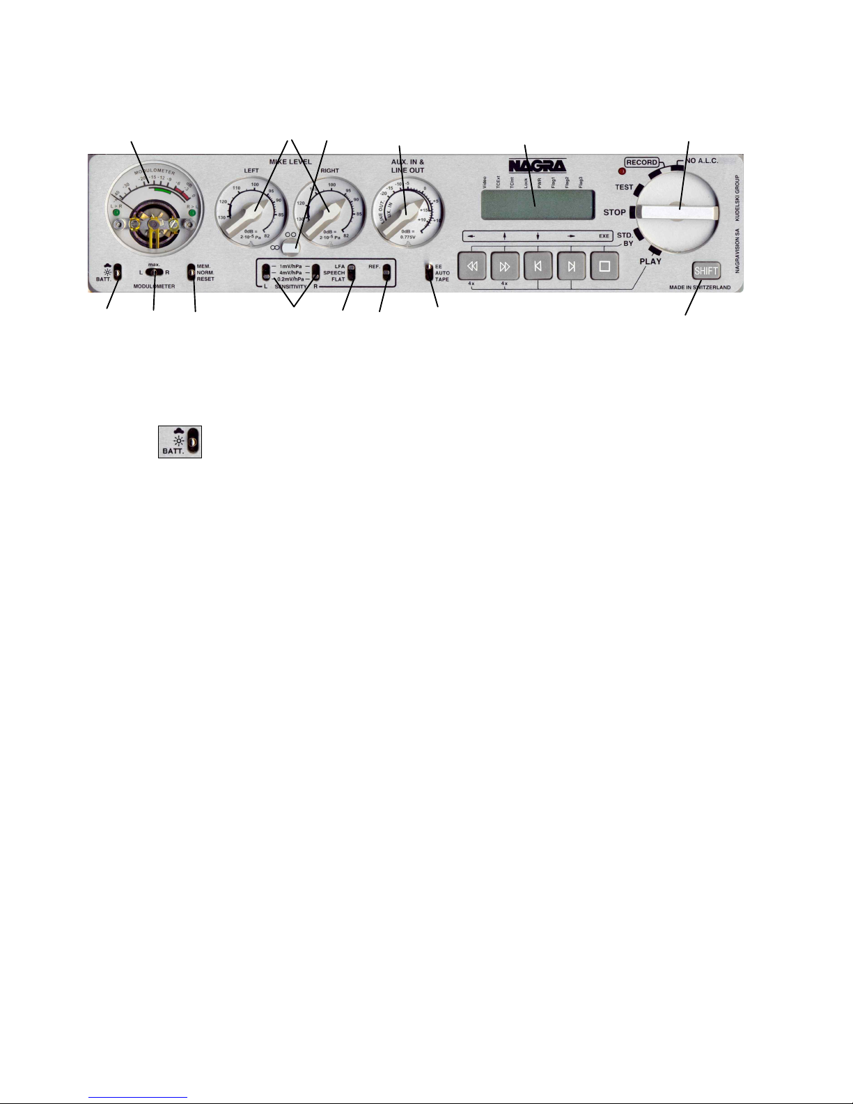
Meter (2)
The NAGRA V can be supplied with either a single or double
pointer modulometer. The double meter is greatly
appreciated in Cinema or two track applications while in
Music or broadcast applications the single pointer instrument
is often preferred. In both cases, the meter is microprocessor
controlled, and has ballistics similar to those of a
modulometer. It can also be used to indicate the condition of
the power source. Fitted with two leds, it will also show the
level of the corresponding channel in the 2 Channel menu
setting or the Highest when set to the Stereo mode.
The meter scale is calibrated from - to 0 in dB however, if the meter is selected to monitor the input
signal (internal jumpers) and there is an indication above the 0dB point, this means that the A/D
converter will be overloaded. The red area (-6 to 0 dB) is the headroom area. When the BATT switch
is pressed, the green area gives information about the power status. See more information in chapter
4.
The channel being indicated depends on the position of the meter selection switch #3 on machines
fitted with the single pointer version.
Attention: From the box motherboard 9131 300 000 B, when moving the 2 internal jumpers, the
meter can be set before or after the Line Output potentiometer. This can only be done by a Nagra
Service Center. See also chapter 4.
Meter Selection Switch (3)
The meter selection switch allows the operator to decide which channel, Left, Right or
MAX, will be displayed on the meter. The MAX position will indicate the highest level
obtained between the two channels and the leds will indicate which channel this corresponds to. From
the box motherboard 9131 300 000 B, the switch will monitor the selected channel in the headphones
in Solo mode (mono). Older boards can be modified to obtain this function. In the case that the
machine is equipped with a double modulometer, the switch #3 does not influence the modulometer
but only the solo selection for the headphones.
Mem / Norm / Reset Switch (4)
This is a three-position switch. In the NORM position the meter will indicate in the normal
manner according to the signal on the input or output (depending on the selection). In the
MEM position the highest obtained level (since the last reset) will be indicated. The reset
position is a snap-switch position and is used to reset the MEM mode. This switch can be moved freely
at any time without affecting the recording. In stereo operation of the machine the function of this
switch is linked to switch #3.
Mike Level Potentiometers (5)
These two potentiometers are used to finely control the sensitivity of the
microphone inputs. If the sensitivity selector is set to 0.2 mV/hPa and the level
potentiometer is set to 82 dB (maximum gain) and the modulometer shows 0
dB, this corresponds to an acoustic level of 82 dBspl.
The bold black area on the scale from 120 to 130 dB is an important indication.
If the potentiometer is set inside this area for the meter to indicate 0 dB, it
means that a 100 dB dynamic range is present. If the potentiometer needs to be
adjusted between 130 dB and 150 dB for the meter to indicate 0 dB, then this
indicates that the input signal is so strong that the microphone pre-amplifiers are overloaded. Above
the 120 dB mark indicating 0 dB on the meter will not cause the input stages to overload but the pre-
amp noise will increase.

Chapter I 7 Oct 2002
Sensitivity Selectors (6)
These two switches are used to select the desired sensitivity of the microphones
connected to the microphone inputs. The possible selections are 1 mV/hPa, 4
mV/hPa and 0.2 mV/hPa. Depending on the type of microphones used, those
switches must be set to the corresponding sensitivity. These switches are especially short to avoid
accidental modification and need to be operated with a small screwdriver or pen.
Rotary Lock (7)
Used to lock the two mike pots mechanically together. When the button is in the horizontal
position "" then the two potentiometers are mechanically locked together irrespective of
their individual positions. In the vertical position " " the potentiometers are totally
independent. In order for the button to be moved to the horizontal position it must be slightly
depressed.
LFA / Speech / Flat (8)
This is the filter selection switch. The filters available are the same as those on other
NAGRA models and act on both the microphone and Line Inputs. The corresponding
curves for the filters are shown:
FLAT filter response curve
(Measurement at AES bus output)
LFA filter curve
(Measurement at AES bus output)
Speech filter curve (Measurement
at AES bus output)
-30
+5
-25
-20
-15
-10
-5
+0
d
B
F
S
20 30k50 100 200 500 1k 2k 5k 10k
Hz
-30
+5
-25
-20
-15
-10
-5
+0
d
B
F
S
20 30k50 100 200 500 1k 2k 5k 10k
Hz
-30
+5
-25
-20
-15
-10
-5
+0
d
B
F
S
20 30k50 100 200 500 1k 2k 5k 10k
Hz

Chapter I 8 Jan 2003
Reference Switch (9)
By pushing the switch upwards, the internal reference generator can be activated. As long as
the switch is held in this position, a sine wave of 1 kHz (at 48/96 kHz, 919 Hz at 44.1/88.2
kHz), will be present at the outputs, if the NAGRA-V is in the test position. When the
reference switch is held in the upper position during record, this signal will be recorded. No indication
is given on the modulometer. While the reference signal is activated, the input signals are muted. The
reference level is factory set to 18 dB.
Aux In and Line Out Potentiometer (10)
This potentiometer has two different functions according to the choice made in
the menu mode. If the menu is selected to LINE OUT then this pot will adjust the
Line Output level of both channels simultaneously, as well as the headphone
and loudspeaker level. Its position is memorised by the microprocessor of the
machine. That is to say, if the pot is set to the +6 dB position, then 0dB on the
meter will give a Line Output of 1.55 V or +6 dBm. If the menu is now changed to
use this pot to control the AUX IN input then the initial output setting will be stored
in the memory of the machine and will remain at 1.55V. Once the menu is set to
the AUX IN mode then this pot serves to adjust the level of the AUX Line Input coming from the 15
pole "D" type EXTENSION connector. Equally if the user changes the use of this pot back to LINE
OUT, then the previously set off the AUX IN level will be stored in the memory. These modes can be
reached using a shortcut by pressing the SHIFT key to go rapidly to input or output adjustment
(depending on the settings made in the menus).
EE / Auto / Tape (11)
EE position: Only the input signals will be available at the outputs (EE means Electronic-
Electronic). TAPE position: This position simulates the behaviour of a tape transport. The
output signals are sounds coming from the disk, the input signals when in the record mode
or in test mode, the recorded sounds when playing back, rewinding, etc.... and muted in stop. AUTO
position: This position will automatically select the EE mode or TAPE mode depending on the status
of the transport. Note: When CAM. RET (camera return) is selected, the camera return signal is
available on the speaker and headphones only in TAPE position. Switching between TAPE and AUTO
position is a fast way to select CAM.RET. or LINE OUT as monitoring source
Main Function Selector (12)
The rotary main function selector is the principle-operating switch for the NAGRA-V. It is a six position
rotary selector. Operation of each position is explained below. The present settings of the menus of
the machine will be scrolled through on the front panel display each time the machine is switched ON.
STOP. This is the main OFF position of the machine. None of the circuits of
the machine are powered in this position. When this position is selected the
machine will switch off after a few seconds if in the Power Delay menu,
Manual is not set.
If Manual is selected, the PC will remain operational. To stop the machine in
this mode the SHIFT button should be pressed and held for minimum 2
seconds while the Main selector is set to STOP.
TEST. In this position all the circuits are powered allowing the adjustment of
levels and signal monitoring. This can be considered as a "stand-by before
record" position. All menu verification and settings can be made in this position.
If the PREREC is set to ON, the record led will start blinking, and meaning that
the closed loop recording (into memory) is active.

Chapter I 9 Jan 2003
RECORD. The record position, marked RECORD is the standard position
used for recording and the internal limiters (if fitted) NV-LIM #7031 130 000 will
be active and turned on (in the limiter sub-menu). When recording, the red led
beside the main function selector will be alight.
When recording, pressing the grey STOP key will automatically create a new
take number without interruption in the recording process. The position "No
A.L.C." is the position for recording without the internal limiters (if fitted).
STD. BY. In this position the grey push-button switches are activated and will
act for rewind, fast forward, skip then stop in both directions and STOP
features.
Access to all the menus & settings of the machine is also enabled.
Rewind at 80 times nominal speed.
Fast Forward at 80 times nominal speed
Skip back by one take and then STOP. The first time this is pressed it will skip
to the beginning of the current take.
Skip forward by one take and STOP.
STOP during rewind or fast forward.
This is the normal PLAYBACK position. The NAGRA V will go into playback
mode either from where the machine was after the previous play, or from the
beginning of the last recorded take if the machine had previously been in
record mode. Once the play mode has been selected the five grey push-button
switches below the display also become active (see below).
Rewind at four times nominal speed.
Forward at four times nominal speed
Skip back followed by PLAY by one take each time it is pressed.
The first time this is pressed it will skip to the beginning of the current take.
Skip forward followed by PLAY by one take each time it is pressed.
Toggles between Play and Pause.
Shift Key (13)
Menu mode. The SHIFT key must be pressed (and kept pressed) in order to move through the
menus on the LCD display on the front panel of the NAGRA V. When it is pressed
the five grey transport keys operate using their shifted ARROW features. As soon as
the SHIFT key is released then it will act as an ESC and the display will return to the
main display screen chosen. While in the menu mode the STOP key becomes the
EXECUTE function. When the shift key is pressed rapidly twice, it stays in the menu
mode (Flag 1 on the display is on). To remove the menu mode, press the SHIFT
key once again or move the main rotary selector to another position. A full
description of the menus is explained later in this manual.

Chapter I 10 Jan 2003
Sync mode. When the shift key is pressed and held while moving the rotary selector to the PLAY
position, the machine turns on the SYNCHRONIZER. The sync mode turns off by
moving the rotary selector.
Power delay. In the case that the POW. DELAY menu is set to MANUAL, press and hold the shift
key while turning the rotary selector to the STOP position. Keep the shift key still
pressed for 2 seconds until the machine turns OFF.
Speaker. Turning ON,OFF or selecting AUTO switching the speaker without going into the
menus, can be made by keeping the shift key pressed while pushing the BATT
switch. Every time this function is executed, it will scroll on the display through the 3
different possibilities.
In/Out pot.This give access to the mode of operation of the third potentiometer on the front
panel of the machine (AUX IN & LINE OUT) in the case that in the menu, the line
potentiometer of the NAGRA V is set to the POT.SHIFT position. That is to say that it
will adjust the input signal if the SHIFT key is kept pressed and it will adjust the
OUTPUT signal if the SHIFT key is not pressed.
Recall 1 Shortcut: When the shift key is pressed and also the left arrow key, the template
recall menus are immediately displayed.
LCD Display (14)
This is a 14 segment 8 digit back lit LCD display, permitting alpha-
numeric indication of a large quantity of different information and
allowing internal settings of the machine to be made in the MENU
mode. In normal operation it will indicate the current take number and
time from the beginning of it. It is also used to display the internal
STATUS of the machine, remaining time available on the cartridge to be recorded etc. The display will
be illuminated if the illumination switch # 1 is put in the "cloud" position.
It can be used to display the following:
Menu Tree
Take Number and time from start of take
Remaining Time on the cartridge/HDD (related to bit & sampling rates)
Time Code
Error codes
Flags on top of the display:
Video If a valid video versus TC format is connected
Tcext If external time code is present
Tcint If during playback the time code is accurate
Lock If the machine is locked in chase mode
PWR If the batt. or ext. voltage drops below limit
Flag 1 If the SHIFT button was pressed twice (menu lock)
Flag 2 Not used
Flag 3 Not used

Chapter I 11 May 2002
RIGHT SIDE PANEL
Banana Output Connectors (1)
This is the telephone output connection. It is a mono output fitted with a transformer with
output impedance of 600 from 300 Hz to 5 kHz, and is used for connection to a standard
switched telephone line. The output level of this connection can be selected in the TEL
LEVEL position of the menu mode to be either 1.55V or 4.4V. When in operation, the return
feed from the telephone can be heard in the headphones or on the internal loudspeaker if
selected.
Line Output Connectors (2)
These two 3 pole XLR female connectors are the standard analog audio
transformer-less outputs. The level of which can be controlled by the Line Output
potentiometer on the front panel (providing it has been previously selected). The
nominal output level on these connectors is 1.55V for 0 dB on the meter.
Pin # Connection
1 Ground
2 Audio signal High
3 Audio signal Low
WARNING: Be sure not to connect these outputs to a mixer supplying 48V phantom as this will damage
the outputs.
AES Output Connector (3)
The 3 pole male XLR AES output connector is a digital output corresponding to the
format of the AES bus used throughout the professional audio industry. The
resolution is of 16 bits or 24 bits depending of the output settings. This connection
allows direct connection to any other digital equipment equipped with an AES
interface
1
2 3
4 5
67
8

Chapter I 12 May 2002
Headphone Output Jack (4)
This is a standard ¼" Stereo Jack connector. The level of the headphone output can be
adjusted using the headphone level control. When the NAGRA-V is connected to a
standard telephone line the return feed of the line is always available in the headphones.
The output pot will also affect the headphone level.
Headphone and Speaker Level Control (5)
Rotary volume control for the headphones. This potentiometer acts as if it is in series with
the output level potentiometer.
External Sync. or Video Input (6)
If the NAGRA-V is fitted with the internal Time Code option then this is the connector
where a video signal (PAL, NTSC, NTSC B/W, 75 Ohms internally loaded) or an
external work clock can be imported. The external sync input is yet another way to
synchronise the internal clocks of the NAGRA-V. The advantage of this 5V logic input is
that it can be used to control the VCXO (Voltage Controlled Crystal Oscillator) from an
external source. The input can be 44.1 kHz, 48 kHz, 88.2 kHz or 96 kHz with a logic voltage level
from min. 0.5 V to 5.0 V. This signal can be fed to the machine through the BNC connector.
Operation of the Time Code is covered in detail in CHAPTER 3 of this manual.
Time Code In/Out Lemo Connector (7)
The time code input and output is located on a 5 pole LEMO connector, the pinning of
which corresponds to that of the IV-STC, the NAGRA-D and T-Audio-TC. The time code
system of the NAGRA-V is more versatile than that of the IV-STC or NAGRA T-Audio. It
offers possibilities that were not previously available and also requires care on the part of
the operator to ensure that the correct information is being recorded and displayed at all
times.
Operation of the Time Code is covered in detail in CHAPTER 3 of this manual.
(QCTCU cable # 7016909000 LEMO to open-ended TC cable)
Camera Monitor Return (8)
This input can be used to return the audio signal from a camera to the headphones (or
speaker) of the Nagra-V. If in the menu CAMERA RETURN is set, the selection between
the return signal or the Nagra-V inputs or playback signals is made by the EE/AUTO/TAPE
selector. In the TAPE position, only the camera return signal goes to the speaker (headphones). This
return signal can not be recorded on the disk.
The return level can only be adjusted via the menu settings. See chapter 2.
Note: Early Nagra-Vs have MON. instead off CAM. RET.printed on the panel

Chapter I 13 May 2003
TOP DECK
Internal Speaker (1)
This small built-in loudspeaker can be used to listen to the recordings. The Line Out level
potentiometer controls the volume of the internal loudspeaker on the front panel of the machine and
in conjunction with the headphone level pot. The speaker can be switched ON, OFF or AUTOMATIC
in the menu mode or with the combination of the SHIFT button & the BATT switch.
Front of the HDD drawer (2)
A little switch permits the powering of the HDD
drawer. In the power on position, on the left side of
the drawer, a little bracket will appear and locks it
mechannically inside the carrying bay of the
Nagra-V.
Attention: Never remove or insert the HDD from
a Nagra-V if it is in the power on mode. Always
shut down the machine, change the drive, put the
power swicth on the drawer to on and turn on the
Nagra-V.
1
2
This manual suits for next models
1
Table of contents
Other Nagra Recording Equipment manuals

Nagra
Nagra E User manual

Nagra
Nagra Nagra-VI User manual

Nagra
Nagra Ares-M User manual

Nagra
Nagra NAGRA 4.2 User manual

Nagra
Nagra LB User manual

Nagra
Nagra Ares-M Audio Recorder User manual

Nagra
Nagra SNST-R User manual

Nagra
Nagra NAGRA 4.2 User manual

Nagra
Nagra IV-S User manual

Nagra
Nagra Nagra-D User manual