Cebora 210.20 User manual

3.300.185-D 02-10-2013
I
MANUALE DI ISTRUZIONI PER INTERFACCIA DIGITALE
ROBOT, Art. 210.20, PER INSTALLAZIONI MIG E TIG ROBOT. pag. 2
GB
INSTRUCTIONS MANUAL FOR ROBOT DIGITAL INTERFACE,
Art. 210.20, FOR MIG AND TIG ROBOT INSTALLATIONS. page 13
E
MANUAL DE ISTRUCCIONES PARA INTERFAZ DIGITAL
ROBOT, Art. 210.2
0, PARA INSTALLACCIONES MIG Y TIG
ROBOT.
pag. 24

2 3.300.185-D
I
IMPORTANTE: PRIMA DELLA MESSA IN
OPERA DELL'APPARECCHIO LEGGERE IL
CONTENUTO DI QUESTO MANUALE E
CONSERVARLO, PER TUTTA LA VITA
OPERATIVA, IN UN LUOGO NOTO AGLI
INTERESSATI. QUESTO APPARECCHIO
DEVE ESSERE UTILIZZATO
ESCLUSIVAMENTE PER OPERAZIONI DI
SALDATURA.
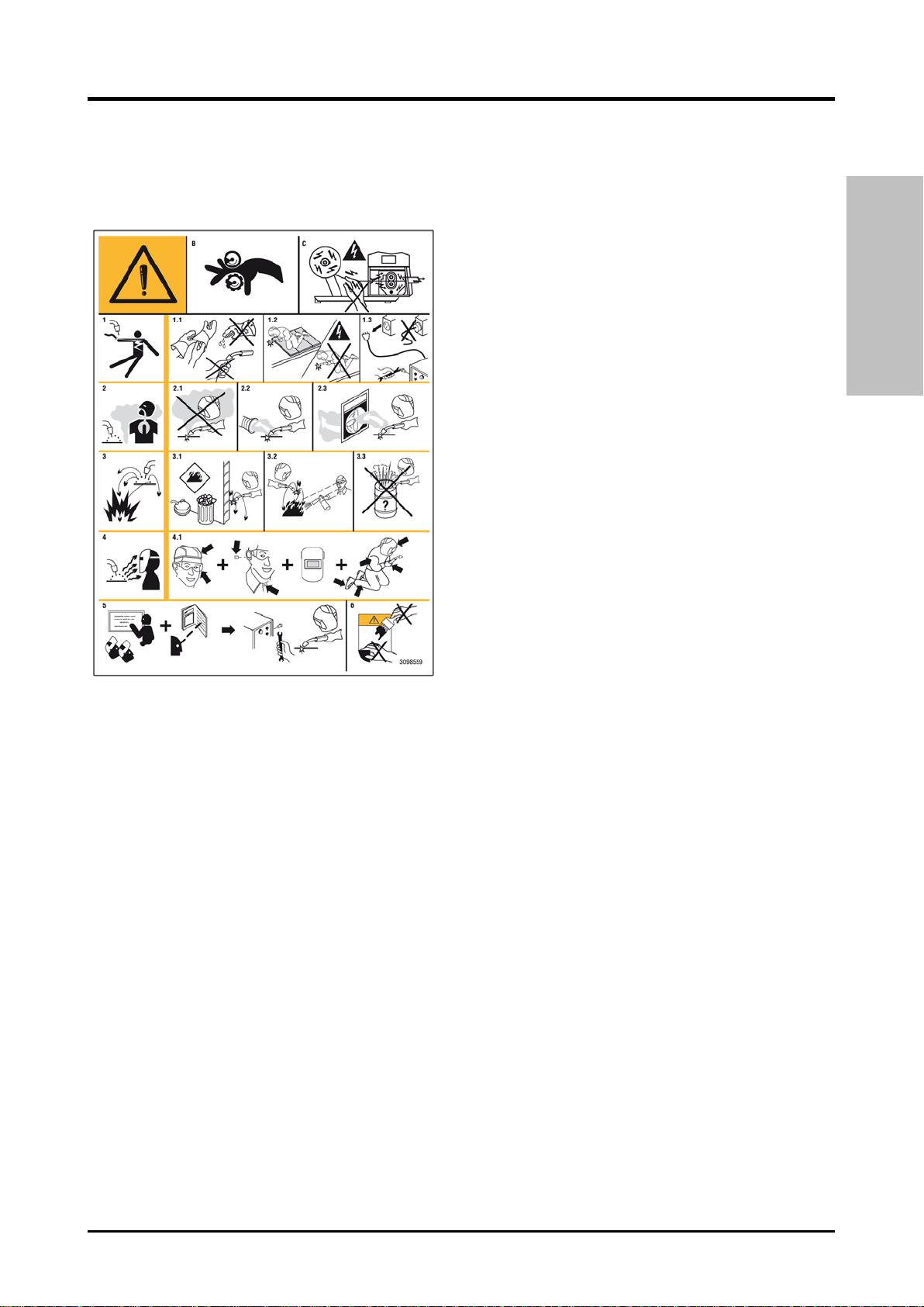
1PRECAUZIONI DI SICUREZZA.
LA SALDATURA ED IL TAGLIO AD ARCO
POSSONO ESSERE NOCIVI
PER VOI E PER GLI ALTRI,
pertanto l'utilizzatore deve
essere istruito contro i rischi, di seguito riassunti,
derivanti dalle operazioni di saldatura. Per
informazioni più dettagliate richiedere il manuale
cod. 3.300.758.
RUMORE.
Questo apparecchio non produce di per
se rumori eccedenti gli 80dB. Il
procedimento di taglio plasma/saldatura
può produrre livelli di rumore superiori a tale
limite; pertanto, gli utilizzatori dovranno mettere in
atto le precauzioni previste dalla legge.
CAMPI ELETTROMAGNETICI. Possono essere
dannosi. La corrente elettrica che
attraversa qualsiasi conduttore
produce dei campi elettromagnetici
(EMF). La corrente di saldatura o di
taglio genera campi elettromagnetici
attorno ai cavi ed ai generatori.
I campi magnetici derivanti da correnti elevate
possono incidere sul funzionamento di pacemaker.
I portatori di apparecchiature elettroniche vitali
(pacemaker) devono consultare il medico prima di
avvicinarsi alle operazioni di saldatura ad arco, di
taglio, scriccatura o di saldatura a punti.
L’ esposizione ai campi elettromagnetici della
saldatura o del taglio potrebbe avere effetti
sconosciuti sulla salute. Ogni operatore, per ridurre
i rischi derivanti dall’ esposizione ai campi
elettromagnetici, deve attenersi alle seguenti
procedure:
- Fare in modo che il cavo di massa e della pinza
portaelettrodo o della torcia rimangano
affiancati. Se possibile, fissarli assieme con del
nastro.
- Non avvolgere i cavi di massa e della pinza
porta elettrodo o della torcia attorno al corpo.
- Non stare mai tra il cavo di massa e quello della
pinza portaelettrodo o della torcia. Se il cavo di
massa si trova sulla destra dell’operatore anche
quello della pinza portaelettrodo o della torcia
deve stare da quella parte.
- Collegare il cavo di massa al pezzo in
lavorazione più vicino possibile alla zona di
saldatura o di taglio.
- Non lavorare vicino al generatore.
ESPLOSIONI.
Non saldare in prossimità di recipienti a
pressione o in presenza di polveri, gas o
vapori esplosivi.
Maneggiare con cura bombole e regolatori di
pressione utilizzati nelle operazioni di saldatura.
COMPATIBILITÀ ELETTROMAGNETICA.
Questo apparecchio è costruito in conformità alle
indicazioni contenute nella norma IEC 60974-
10(Cl. A) e deve essere usato solo a scopo
professionale in un ambiente industriale. Vi
possono essere, infatti, potenziali difficoltà
nell'assicurare la compatibilità elettromagnetica
in un ambiente diverso da quello industriale.
SMALTIMENTO APPARECCHIATURE
ELETTRICHE ED ELETTRONICHE.
Non smaltire le apparecchiature
elettriche assieme ai rifiuti normali!
In ottemperanza alla Direttiva Europea
2002/96/CE sui rifiuti da apparecchiature elettriche
ed elettroniche e relativa attuazione nell'ambito
della legislazione nazionale, le apparecchiature
elettriche giunte a fine vita devono essere raccolte
separatamente e conferite ad un impianto di riciclo
ecocompatibile. In qualità di proprietario delle
apparecchiature dovrà informarsi presso il nostro
rappresentante in loco sui sistemi di raccolta
approvati. Dando applicazione a questa Direttiva
Europea migliorerà la situazione ambientale e la
salute umana!
IN CASO DI CATTIVO FUNZIONAMENTO
RICHIEDETE L’ASSISTENZA DI PERSONALE
QUALIFICATO.

3.300.185-D 3
I
1.1 Targa delle AVVERTENZE.
Il testo numerato seguente corrisponde alle caselle
numerate della targa.
B I rullini trainafilo possono ferire le mani.
C Il filo di saldatura ed il gruppo trainafilo sono
sotto tensione durante la saldatura. Tenere
mani ed oggetti metallici a distanza.
1 Le scosse elettriche provocate dall’elettrodo
di saldatura o dal cavo possono essere letali.
Proteggersi adeguatamente dal pericolo di
scosse elettriche.
1.1 Indossare guanti isolanti. Non toccare
l’elettrodo a mani nude. Non indossare guanti
umidi o danneggiati.
1.2 Assicurarsi di essere isolati dal pezzo da
saldare e dal suolo.
1.3 Scollegare la spina del cavo di alimentazione
prima di lavorare sulla macchina.
2 Inalare le esalazioni prodotte dalla saldatura
può essere nocivo alla salute.
2.1 Tenere la testa lontana dalle esalazioni.
2.2 Utilizzare un impianto di ventilazione forzata
o di scarico locale per eliminare le esalazioni.
2.3 Utilizzare una ventola di aspirazione per
eliminare le esalazioni.
3 Le scintille provocate dalla saldatura possono
causare esplosioni od incendi.
3.1 Tenere i materiali infiammabili lontano
dall’area di saldatura.
3.2 Le scintille provocate dalla saldatura possono
causare incendi Tenere un estintore nelle
immediate vicinanze e far sì che una persona
resti pronta ad utilizzarlo.
3.3 Non saldare mai contenitori chiusi.
4 I raggi dell’arco possono bruciare gli occhi e
ustionare la pelle.
4.1 Indossare elmetto e occhiali di sicurezza.
Utilizzare adeguate protezioni per le orecchie
e camici con il colletto abbottonato. Utilizzare
maschere a casco con filtri della corretta
gradazione. Indossare una protezione
completa per il corpo.
5 Leggere le istruzioni prima di utilizzare la
macchina od eseguire qualsiasi operazione su
di essa.
6 Non rimuovere né coprire le etichette di
avvertenza.

4 3.300.185-D
I
2DESCRIZIONE SISTEMA.
2.1 Composizione.
Il Sistema di Saldatura ROBOT Cebora è un
sistema di apparecchiature idoneo alla saldatura
realizzato per essere abbinato ad un braccio Robot
Saldante, su impianti di saldatura automatizzati.
È composto generalmente da un Generatore,
equipaggiato eventualmente di Gruppo di
Raffreddamento, da un Carrello Trainafilo, da un
Pannello di Controllo e da una Interfaccia Robot
(fig. 2.1).
fig. 2.1
1 Cavo Generatore – Pannello di Controllo.
2 Prolunga Generatore – Carrello Trainafilo.
3 Cavo Generatore – armadio del Controllo
Robot.
4 Cavo CAN bus Generatore – Interfaccia
Robot.
5 Armadio del Controllo Robot.
6 Porta bobina del filo di saldatura.
7 Torcia.
8 Carrello Trainafilo.
10 Guaina del filo di saldatura.
21 Generatore.
22 Gruppo di Raffreddamento.
24 Pannello di Controllo del Generatore.
25 Interfaccia Robot.
26 Cavo “Profibus” (fornito con l’Interfaccia
Robot).
2.2 Questo Manuale Istruzioni.
Questo Manuale Istruzioni si riferisce alla
Interfaccia Digitale Robot RDI210 ed è stato
preparato allo scopo di istruire il personale addetto
all'installazione, al funzionamento ed alla
manutenzione della saldatrice.
Deve essere conservato con cura, in un luogo noto
ai vari interessati, deve essere consultato ogni qual
volta vi siano dubbi ed impiegato per l'ordinazione
delle parti di ricambio e dovrà seguire tutta la vita
operativa della macchina.
ATTENZIONE ! L’utilizzo non appropriato
delle apparecchiature può causare
danni alle apparecchiature e
pericolo per l’operatore.
Non utilizzare le funzioni descritte
nel presente manuale finché non si
sono lette e comprese tutte le parti
dei seguenti documenti:
−questo Manuale Istruzioni;
−il Manuale Istruzioni delle
apparecchiature componenti il
Sistema di Saldatura (es.:
Generatore, Carrello Trainafilo,
Pannello di Controllo compresi
quelli di eventuali opzioni).

3.300.185-D 5
I
2.3 Concetto dell’apparecchiatura.
L’Interfaccia Digitale Robot RDI210, art. 210.20, è
un’interfaccia di collegamento fra Generatore
Cebora e Robot Industriali Saldanti, basata su Bus
Terminal Controller BX3100 Beckhoff.
L’interfaccia RDI210 è realizzata per essere
installata nell’armadio del Controllo Robot.
2.3.1 Caratteristiche principali:
−Collegamento al Generatore via interfaccia
standard CAN bus;
−collegamento al Controllo Robot via interfaccia
standard Profibus-DP;
−connessioni con connettori;
−assemblaggio su guida DIN;
−dimensioni (p x l x a) = 83 x 100 x 91 mm.
2.4 Composizione art. 210.20 (fig. 2.4).
L’Interfaccia Digitale Robot RDI210, art. 210.20, è
composta dal Bus Terminal Controller BX3100
Beckhoff, dal cavo CAN bus (4) e dal cavo
Profibus (26).
Il cavo CAN bus (4), lungo 1,5 m, è preassemblato
con un connettore femmina da pannello, a 10 poli,
da utilizzare come passaggio attraverso la parete
dell’armadio del Controllo Robot e con connettore
Sub-D 9 poli, per la connessione all’Interfaccia.
Il cavo Profibus (26), lungo 2 m, è un cavo a 4 fili
più schermo, preassemblato con due connettori
Sub-D a 9 poli maschio.
L’Interfaccia Digitale Robot, art. 210.20 è
collegata al connettore CAN bus del Generatore
tramite il cavo dei segnali (3).
fig. 2.4
3BUS TERMINAL CONTROLLER - BX3100.
3.1 Hardware lay-out.
fig. 3.1

6 3.300.185-D
I
3.2 Dati tecnici.
Bus di campo Profibus DP.
Profibus Baud rate fino a 12 Mbps, selezione
automatica.
Numero di moduli
sul K-bus 0 ÷ 64.
Numero di byte
sul K-bus 244 byte max. d’ingresso,
244 byte max. d’uscita.
SSB interfaccia basata su bus
CANopen.
Interfaccia per
programmazione COM1 (RS232).
Programmazione
e configurazione via software CFC Tool.
Alimentazione 24 Vdc,-15% / +20%.
Corrente assorbita 140 mA tipico + (corrente
del K-bus)/4.
Corrente assorbita
sul K-bus 1,45 A max.
Alimentazione
“Power contacts” 24 VDC.
Corrente nei
“Power contacts” 10 A max.
Isolamento 500 Vrms (alimentazione
BX3100 / “Power contacts”
/ bus di campo).
Peso 250g.
Temperatura
di funzionamento 0 °C ... +55 °C.
Temperatura
immagazzinamento -25 °C ... +85 °C.
Umidità relativa 95% senza condensa.
Vibrazioni
/ resistenza agli urti secondo EN 60068-2-6 / EN
60068-2-27/29.
EMC, burst / ESD secondo EN 61000-6-2 / EN
61000-6-4.
Posizione di
montaggio qualsiasi.
Grado di protezione IP20.
3.3 Alimentazioni.
Il Bus Terminal Controller BX3100 presenta 3
differenti blocchi di potenziale:
−logica del Bus Terminal Controller ed
accoppiatore di bus;
−moduli I/O aggiuntivi, alimentati tramite i
contatti di potenza (“Power contacts”, in fig.
3.1);
−interfaccia del bus di campo (“Fieldbus
connection”, in fig. 3.1).
Ognuno di questi blocchi lavora con un potenziale
di tensione isolato da quello degli altri due.
3.3.1 Alimentazione Bus Terminal
Controller.
Il Bus Terminal Controller richiede
un’alimentazione a 24 VDC.
Questa tensione alimenta sia la parte elettronica del
modulo BX3100 sia i Moduli I/O aggiuntivi,
collegati al BX3100 tramite il K-bus.
La connessione dell’alimentazione è realizzata
tramite i morsetti a molla chiamati 24 V e 0 V.
3.3.2 Alimentazione “Power contacts”.
Le 6 connessioni inferiori con morsetti a molla
possono essere usate per fornire l’alimentazione
alle unità periferiche esterne.
I morsetti a molla sono collegati in coppia fra loro
per consentire il collegamento a ponte fra i diversi
Moduli I/O aggiuntivi.
I morsetti accettano fili con sezioni da 0,08 mm2a
2,5 mm2.
La capacità di corrente di due morsetti a molla è
pari a quella dei fili di collegamento.
Il potenziale dei circuiti dei Moduli I/O aggiuntivi
è isolato rispetto al potenziale dell’alimentazione
della parte elettronica del BX3100.
Il progetto di tali circuiti consente tensioni di
alimentazione fino a 24 V.
Sul lato destro del Bus Terminal Controller ci sono
3 contatti a lamella (“Power contacts” in fig. 3.1)
per la distribuzione della tensione per le unità
periferiche esterne ai vari Moduli I/O aggiuntivi.
I contatti a lamella sono nascosti negli slot in modo
che non possano essere toccati accidentalmente.
Inserendo un Modulo I/O aggiuntivo, i contatti a
lamella sul lato sinistro del Modulo I/O aggiuntivo
si connettono con i contatti a lamella del Bus
Terminal Controller.

3.300.185-D 7
I
La linguetta in plastica (di colore arancio in fig.
3.1) e le guide della scanalatura in alto e in basso
nel Bus Terminal Controller e nei Moduli I/O
aggiuntivi, garantiscono che i contatti a lamelle
siano saldamente effettuati.
La corrente di carico dei “Power contacts” non
deve superare i 10 A per lunghi periodi.
Il terminale a molla chiamato PE può essere
utilizzato come connessione protettiva di messa a
terra. Tale terminale è connesso via capacitiva con
la guida DIN di montaggio del Bus Terminal
Controller.
3.4 Connettori.
X20 – CANopen (interfaccia SSB).
X20
Pin
Segnale
1
riservato
2
CAN low
3
GND
4
riservato
5
schermo
6
GND
7
CAN high
8
riservato
9
riservato
X21 – Programmazione (COM 1 - RS 232).
X21
Pin
Interfaccia
Segnale
1
COM2
RS485 D+
2
COM1
RS232 TxD
3
COM1
RS232 RxD
4
VCC +5 V
VCC
5
GND
GND
6
COM2
RS485 D-
7
COM2
RS232 RxD
8
COM2
RS232 TxD
9
GND
GND
X310 – Interfaccia Profibus
X310
Pin
Segnale
1
non usato
2
non usato
3
segnale P Profibus
4
non usato
5
GND
6
+ 5Vdc
7
non usato
8
segnale N Profibus
9
non usato
3.5 Interfaccia Profibus.
Tipologia rete bus lineare con terminatori di
bus attivi su entrambi i capi.
Mezzo cavo schermato a due coppie di
conduttori attorcigliati. Lo
schermo può essere richiesto
dalle normative EMC.
Velocità di
trasmissione fino a 12 Mbps, selezione
automatica.
Massima
lunghezza del bus 400 m @ 500 Kbit/s. (100 m @
12 Mbit/s).
Connettori Sub-D 9 poli, maschio.
NOTA:Un circuito watchdog impone al
Generatore di interrompere la saldatura in
caso di interferenze nella trasmissione dati
o interruzione della linea di trasmissione.
Se la trasmissione dati non inizia entro 1 s,
tutti i segnali sono resettati ed il
Generatore rimane nello stato di stop.
Tutti i segnali del Profibus provenienti dal
Generatore sono impostati a 0 se la
comunicazione CANopen non è attiva.
3.6 Cavo Profibus.
Il Bus Terminal Controller BX3100 presenta nella
parte sinistra l’alloggiamento per il connettore
Sub-D a 9 poli.
Il cavo Profibus, fornito a corredo, deve essere
collegato a questo connettore. Tale cavo è di tipo
schermato a due coppie di conduttori attorcigliati;
una coppia di conduttori è per la trasmissione dati,
l’altra coppia per l’alimentazione.
La figura mostra i collegamenti del cavo Profibus.
Il pin 3 è relativo al segnale P del Profibus.
Il pin 5 è relativo al GND della alimentazione del
circuito terminatore attivo di linea.
Il pin 6 è relativo al +5 VDC della alimentazione del
circuito terminatore attivo di linea.
Il pin 8 è relativo al segnale N del Profibus.
Lo schermo del cavo deve essere collegato al
guscio del connettore Sub-D a 9 poli.
Sul Bus Terminal Controller BX3100, il corpo del
connettore è accoppiato con una bassa resistenza
alla guida DIN di montaggio del modulo stesso.

8 3.300.185-D
I
Siccome il Bus Terminal Controller BX3100
provvede anche all’isolamento galvanico del
collegamento del bus, in alcuni casi può essere
possibile non effettuare il collegamento dello
schermo.
3.7 Configurazione del Bus Terminal
Controller.
Prima di utilizzare il Bus Terminal Controller
occorre impostare il “numero del nodo” sulla rete
Profibus. Questa impostazione è
effettuabile tramite i due rotary
switches sul Bus Terminal
Controller, visibili in figura.
−Switch x1 per bit meno
significativo;
−Switch x10 per bit più
significativo.
NOTA:L’esempio a lato indica
“numero del nodo” impostato a 5.
3.8 Diagnostica.
Il Bus Terminal Controller dispone di due gruppi
di led ed un display per la diagnostica:
−“Power Leds” per il controllo delle tensioni di
alimentazione del BX3100 e dei “Power
contacts”.
−“Diag Leds” per la condizione del bus di campo
(Profibus), del PLC (BX3100) e del K-bus.
−“Display” per la visualizzazione dello stato
operativo, e dei “Codici Errore”
3.8.1 Led alimentazioni (Power Leds).
Power Leds
Descrizione
Led di sinistra
spento
Tensione alimentazione
del BX3100 assente.
Led di sinistra
acceso
Tensione alimentazione
del BX3100 corretta.
Led di destra
spento
Tensione alim. “Power
contacts” assente.
Led di destra
acceso
Tensione alim. “Power
contacts” corretta.
3.8.2 Led di diagnostica (Diag Leds).
I led di diagnostica sono
suddivisi come segue:
Bus: diagnosi del bus di
campo (Profibus).
PLC: diagnosi del PLC
(BX3100).
I/O: diagnosi del K-bus.
I leds possono essere spenti, verdi, arancio o rossi.
Dopo lo start up il Bus Terminal Controller
verifica immediatamente la configurazione
connessa:
−se lo start up è avvenuto correttamente, il led
I/O si spegne.
−il led I/O rosso acceso, indica un errore nel Bus
Terminal Controller ed il tipo di errore è
indicato nel display.
3.8.3 Led per diagnosi del bus di campo.
Led Bus
Descrizione
Off
Nessun bus di campo
collegato. Il Bus Terminal
Controller ricerca Baud rate.
Rosso
lamp.
Errore. Il tipo di errore è
indicato nel display.
Arancio
fisso
Il Bus Terminal Controller ha
trovato il Baud rate attivo ed
è in attesa dei dati per la
configurazione.
Verde
fisso
Comunicazione sul bus
attiva, il Bus Terminal
Controller sta scambiando
dati.
3.8.4 Led per diagnosi PLC.
Led PLC
Descrizione
Off
PLC in stop o nessun
programma disponibile.
Rosso
lamp.
Tempo di ciclo del PLC a
volte eccessivo.
Rosso
fisso
Tempo di ciclo del PLC
sempre eccessivo.
Arancio
lamp.
Fase di creazione del
progetto di boot.
Arancio
fisso
Il PLC funziona senza
progetto di boot (acceso solo
durante il ciclo).
Verde
fisso
Progetto di boot – PLC
funzionanti (acceso solo
durante il ciclo).

3.300.185-D 9
I
3.8.5 Led diagnosi del K-bus.
Led I/O
Descrizione
Off
Nessun dato è scambiato via
K-bus.
Rosso
lamp.
Errore. Il tipo di errore è
indicato nel display.
Arancio
fisso
Accesso online al Registro o
al KS2000.
Verde
fisso
K-bus correttamente
funzionante.
3.8.6 Display di diagnostica.
Durante lo start up il display mostra la versione del
firmware corrente per 3 secondi.
Un eventuale errore durante lo start up, è indicato
da una sequenza di lampeggi del led associato.
Gli errori di configurazione sono indicati sul
display via “TC-Config” ed il numero di errore.
Utilizzare il System Manager per controllare la
configurazione hardware o contattare il servizio
assistenza.
Display
Descrizione
TC-
Config
0xF0nn
Il Bus Terminal n° “nn” non
corrisponde alla configurazione.
Comparare la struttura del bus
del Bus Terminal n° “nn” con la
configurazione.
Errori del firmware sono indicati nel display via
“FW-Error” ed il numero di errore.
Display
Descrizione
FW-Error
0xnnnn
Contattare il servizio
assistenza.
3.9 Codici Errore per diagnostica K-bus.
Per visualizzare un Codice Errore del K-bus:
−premere il Joystick per 3
secondi, per entrare nel
menù di setup del
BX3100;
−premere il Joystick in
posizione Sx o Dx per
navigare all’interno del
menù di setup fino a raggiungere il menù del K-
bus, indicato sul display;
−la segnalazione di un eventuale Codice Errore è
visualizzata sul display;
−i Codici Errore possibili e la relativa
spiegazione sono riportati nella tabella 3.9.1;
−per uscire dal menù di setup premere il Joystick
per 3 secondi.
3.9.1 Codici Errore del K-bus.
Codice
errore
Argo-
mento
Descrizione Soluzione
0 - Problema di EMC.
Controllare che la tensione di alimentazione sia esente
da picchi o buchi di tensione.
Implementare le misure EMC. Se è presente un errore
sul K-bus, può essere localizzato
con il restart del
controller (spegnere e riaccendere).
1
0
Errore di checksum della
eeprom.
Impostare il setup di fabbrica tramite il software di
configurazione KS2000.
1 Code buffer overflow.
Inserire una quantità inferiore di Moduli I/O.
La configurazione programmata ha troppi segnali.
2
Tipo dati sconosciuto.
Aggiornare il software del Bus Terminal Controller.
2
-
Riservato.
-
3 0 Errore nei comandi nel K-
bus.
Nessun Modulo I/O inserito.
Uno dei Moduli I/O è difettoso; dimezzare il numero
dei Moduli I/O
collegati e controllare se l’errore è
ancora presente con i Moduli I/O restanti.
Ripetere finché il Modulo I/O è individuato.
4 0
Errore dei dati del K-bus,
interruzione nel retro del
Bus Terminal Controller.
Controllare se il Modulo I/O
n+1 è correttamente
collegato; sostituirlo se necessario.
n
Interruzione nel retro del
Modulo I/O n.
Controllare che il Modulo Terminatore KL9010 sia
collegato.

10 3.300.185-D
I
5 n
Errore nel K-bus, nel
registro di comunicazione
con il Modulo I/O n.
Sostituire il Modulo I/O n.
6
0
Errore all’inizializzazione.
Sostituite il Bus Terminal Controller.
1 Errore nei dati interni.
Eseguire il reset hardware del Bus Terminal Controller
(spegnere e riaccendere).
2
Rotary switches cambiati
dopo un reset software.
Eseguire il reset hardware del Bus Terminal Controller
(spegnere e riaccendere).
7 0 Tempo di ciclo eccessivo.
Attenzione: il tempo di ciclo programmato è eccessivo.
Questa indicazione (led lampeggianti) può essere
cancellata solo con il riavvio del Bus Terminal
Controller. Rimedio: incrementare il tempo di ciclo.
9 0
Errore di checksum nel
programma della flash.
Trasmettere nuovamente il programma al Bus
Terminal Controller.
1
Libreria implementata non
corretta o difettosa.
Rimuovere la libreria difettosa.
10 n
Il Modulo I/O n. non
concorda con la
configurazione esistente
quando fu creato il “boot
project”.
Controllare il Modulo I/O n..
Il “boot project”
deve essere cancellato se
l’inserimento di un Modulo I/O n. è intenzionale.
14 n
Modulo I/O n. ha un
formato errato.
Rialimentare il Bus Terminal Controller. Se l’errore
persiste, sostituire il Modulo I/O.
15 n Numero d
i Moduli I/O
non più corretto.
Rialimentare il Bus Terminal Controller. Se l’errore
persiste, ripristinare il setup di fabbrica tramite il
software di configurazione KS2000.
16 n Lunghezza dei dati del K-
bus non più corretta.
Rialimentare il Bus Terminal Controller. Se l’errore
persiste, ripristinare il setup di fabbrica tramite il
software di configurazione KS2000.
4CONFIGURAZIONE DATA PROCESS
IMAGE.
4.1 Struttura.
La Data Process Image definisce i segnali
ingresso / uscita scambiati sul bus di campo
Profibus-DP, tra il Controllo Robot (modulo
Master) ed il Bus Terminal Controller BX3100
(modulo Slave).
La dimensione della Data Process Image dipende
da un lato dalla quantità di segnali scambiati fra
Controllo Robot e Generatore e dall’altro dai
segnali scambiati fra Controllo Robot e Moduli
I/O aggiuntivi, eventualmente inseriti sul K-bus.
Per ognuna delle suddette configurazioni viene
fornita una specifica versione del software del
BX3100.

3.300.185-D 11
I
4.2 Data in Process Image fra Controllo
Robot e Generatore.
La configurazione dei messaggi dei bus di campo
(Data Process Image) adottati negli impianti di
saldatura automatizzati Cebora è descritta nei
seguenti manuali, forniti a corredo dei Generatori:
−MIG = cod. 3.300.362;
−TIG = cod. 3.300.363.
In questi manuali sono elencati e descritti tutti i
segnali scambiati fra il Sistema di Saldatura
Cebora ed il controllo dell’impianto robotizzato
(Robot Control).
I primi 128 ingressi e le prime 96 uscite della Data
Process Image sono intese solo per un singolo Bus
Terminal Controller BX3100, senza alcun Modulo
I/O aggiuntivo e riguardano esclusivamente i
segnali Profibus scambiati fra Controllo Robot e
Generatore.
NOTA:Quando si installano Moduli I/O
aggiuntivi, la Data Process Image cambia.
4.3 Data Process Image fra Controllo Robot
e Moduli I/O.
L’interfaccia RDI210, art. 210.20, prevede la
possibilità di espansione con Moduli I/O
aggiuntivi, inseribili sul K-bus.
Gli ingressi da I129 a I256 e le uscite da O97 a
O224 della Data Process Image riguardano
esclusivamente i segnali tra i Moduli I/O
aggiuntivi da un lato ed il Controllo Robot
dall’altro.
4.3.1 Segnali da Controllo Robot a Moduli
I/O.
Ingressi
BX3100
N° bit
Dim.
in bit Segnali Digitali
e/o Analogici Valore
I129 ÷
I256 128
Uscite relative ai
moduli di uscita
inseriti sul K-bus.
Attivo
alto.
4.3.2 Segnali da Moduli I/O a Controllo
Robot.
Uscite
BX3100
N° bit
Dim.
in bit Segnali Digitali
e/o Analogici Valore
O97 ÷
O224 128
Ingressi relativi ai
moduli d’ingresso
inseriti su K-bus.
Attivo
alto.
4.4 Segnali fra Moduli I/O e Generatore.
L’interfaccia RDI210, art. 210.20 prevede anche la
possibilità di scambiare segnali di ingresso / uscita
tra Generatore e Moduli I/O aggiuntivi.
Tali segnali non influiscono sulla definizione della
Data Process Image.
5CONFIGURAZIONI DISPONIBILI
DELLA DATA PROCESS IMAGE.
Le “configurazioni disponibili” della Data Process
Image sono quelle per applicazioni richiedenti il
Bus Terminal Controller BX3100 con Moduli I/O
aggiuntivi.
I Moduli I/O aggiuntivi devono essere scelti in
funzione delle esigenze dell’impianto, tenendo
presente che il loro numero è limitato dal numero
massimo di ingressi ed uscite indirizzabili (128
ingressi e 128 uscite).
Per il corretto funzionamento i moduli aggiuntivi
devono essere alimentati.
NOTA:Per utilizzare il Bus Terminal Controller
BX3100 con Moduli I/O aggiuntivi
occorre richiedere il corrispondente file
.BIN all’Ufficio Tecnico Cebora.
Il file .BIN inserito nella memoria del
BX3100 deve essere compatibile con la
configurazione hardware dei Moduli I/O
aggiuntivi installati.
I Moduli I/O aggiuntivi previsti sono:
Modulo ingressi digitali:
KL1114 4 Ch. Ingresso (24V, 0.2ms);
KL1124 4 Ch. Ingresso (5V, 0.2ms);
KL1154 4 Ch. Ingresso +/- (24V, 3.0ms);
KL1164 4 Ch. Ingresso +/- (24V, 0.2ms);
KL1184 4 Ch. Ingresso negativo (24V,
3.0ms);
KL1194 4 Ch. Ingresso negativo (24V,
0.2ms);
KL1304 4 Ch. Ingresso (24V, 3.0ms, 6mA);
KL1314 4 Ch. Ingresso (24V, 0.2ms, 6mA);
KL1404 4 Ch. Ingresso (24V, 0.2ms, 3mA, 2
wire);
KL1414 4 Ch. Ingresso (24V, 0.2ms, 3mA, 2
wire);
KL1434 4 Ch. Ingresso (24V, 0.2ms, 6mA, 2
wire).

12 3.300.185-D
I
Modulo uscite digitali:
KL2124 4 Ch. Uscita (5V, 20mA);
KL2134 4 Ch. Uscita con protezione (24V,
0.5A);
KL2184 4 Ch. Uscita negativa (24V, 0.5A);
KL2404 4 Ch. Uscita con protezione (24V,
0.5A, 2 wire);
KL2424 4 Ch. Uscita con protezione (24V,
2A, 2 wire);
KL2744 4 Ch. Uscita a relè (230V ac/dc
1.5A).
Modulo terminatore di Bus:
KL9010.
Quando si utilizza una configurazione Hardware
con Moduli I/O aggiuntivi, sul K-bus deve essere
sempre inserito il modulo terminatore KL9010.
Quando inserito sul K-bus, il terminatore KL9010
abilita il controllo di corrispondenza fra la
configurazione del Software e la configurazione
Hardware, perciò la configurazione del Software
deve essere uguale alla configurazione Hardware,
cioè corrispondere ai Moduli I/O inseriti sul K-bus.
Con la versione X.5, cioè quella senza Moduli I/O
sul K-bus, il terminatore può non essere inserito
sul K-bus e la configurazione Hardware può anche
essere diversa dalla configurazione Software.
Se invece il terminatore è inserito sul K-bus, senza
Moduli I/O sul K-bus, la configurazione Hardware
deve essere uguale alla configurazione Software
anche nella versione X.5.
5.1 Versione X.5.
Le dimensioni della Process Image Profibus sono:
256 DI e 224 DO.
Configurazione K-bus. Nessun modulo sul K-bus.
BX3100
Uscite
N° bit
Dim.
in
bit
Segnale Modulo /
Morsetto Valore
O97 ÷
O224
128
Non
usato
- -
BX3100
Ingressi
N° bit
Dim.
in
bit
Segnale Modulo /
Morsetto Valore
I129 ÷
I256
128
Non
usato
- -
5.2 Esempio.
L’esempio illustra il comportamento del Sistema, con Data Process Image in versione X.4, in relazione alle
diverse possibili configurazioni Hardware del Bus Terminal.
* KL
2134 KL
9010
Led di diagnostica Codice
Errore
K-bus
Indicazione sul
display del BX3100
BUS PLC I/O
1 NO NO Verde fisso Verde fisso Rosso lamp. 3
CEBORA GATEWAY
REL. X.4
2 NO SI Verde lamp. Off Rosso lamp. 255 DEFAULT - CONFIG
3 SI NO Verde fisso Verde fisso Rosso lamp.
4
term. X
CEBORA GATEWAY
REL. X.4
4 SI SI Verde fisso Verde fisso Off -
CEBORA GATEWAY
REL. X.4
*1 – Sistema completamente operativo.
*2 – Sistema in blocco : sul Pannello di Controllo compare “Rob” “Int” lampeggiante.
*3 – La comunicazione fra Robot e Generatore è operativa, ma le uscite digitali del modulo KL2134 non
sono funzionanti.
*4 – Sistema completamente operativo.

3.300.185-D 13
GB
IMPORTANT: BEFORE STARTING THE
EQUIPMENT, READ THE CONTENTS OF
THIS MANUAL, WHICH MUST BE STORED
IN A PLACE FAMILIAR TO ALL USERS FOR
THE ENTIRE OPERATIVE LIFE-SPAN OF THE
MACHINE. THIS EQUIPMENT MUST BE
USED SOLELY FOR WELDING OPERATIONS.
1SAFETY PRECAUTIONS.
WELDING AND ARC CUTTING CAN BE
HARMFUL TO YOURSELF
AND OTHERS.
The user must therefore be
educated against the hazards, summarized below,
deriving from welding operations. For more
detailed information, order the manual code
3.300.758.
NOISE. This machine does not directly produce
noise exceeding 80dB. The plasma
cutting/welding procedure may produce
noise levels beyond said limit; users must therefore
implement all precautions required by law.
ELECTRIC AND MAGNETIC FIELDS.
May be dangerous.
Electric current following through
any conductor causes localized
Electric and Magnetic Fields (EMF).
Welding/cutting current creates EMF fields around
cables and power sources.
The magnetic fields created by high currents may
affect the operation of pacemakers. Wearers of
vital electronic equipment (pacemakers) shall
consult their physician before beginning any arc
welding, cutting, gouging or spot welding
operations.
Exposure to EMF fields in welding/cutting may
have other health effects which are now not
known.
All operators should use the following procedures
in order to minimize exposure to EMF fields from
the welding/cutting circuit:
- Route the electrode and work cables together –
Secure them with tape when possible.
- Never coil the electrode/torch lead around your
body.
−Do not place your body between the
electrode/torch lead and work cables. If the
electrode/torch lead cable is on your right side,
the work cable should also be on your right
side.
- Connect the work cable to the workpiece as
close as possible to the area being welded/cut.
- Do not work next to welding/cutting power
source.
EXPLOSIONS.
Do not weld in the vicinity of containers
under pressure, or in the presence of
explosive dust, gases or fumes.
All cylinders and pressure regulators used in
welding operations should be handled with care.
ELECTROMAGNETIC COMPATIBILITY.
This machine is manufactured in compliance with
the instructions contained in the harmonized
standard IEC 60974-10 (CL.A), and must be used
solely for professional purposes in an industrial
environment. There may be potential difficulties
in ensuring electromagnetic compatibility in
non-industrial environments.
DISPOSAL OF ELECTRICAL AND
ELECTRONIC EQUIPMENT.
Do not dispose of electrical equipment
together with normal waste!
In observance of European Directive
2002/96/EC on Waste Electrical and
Electronic Equipment and its implementation in
accordance with national law, electrical equipment
that has reached the end of its life must be
collected separately and returned to an
environmentally compatible recycling facility. As
the owner of the equipment, you should get
information on approved collection systems from
our local representative. By applying this European
Directive you will improve the environment and
human health!
IN CASE OF MALFUNCTIONS, REQUEST
ASSISTANCE FROM QUALIFIED
PERSONNEL

14 3.300.185-D
GB
1.1 WARNING label.
The following numbered text corresponds to the
label numbered boxes.
B Drive rolls can injure fingers.
C Welding wire and drive parts are at welding
voltage during operation — keep hands and
metal objects away.
1 Electric shock from welding electrode or
wiring can kill.
1.1 Wear dry insulating gloves. Do not touch
electrode with bare hand. Do not wear wet or
damaged gloves.
1.2 Protect yourself from electric shock by
insulating yourself from work and ground.
1.3 Disconnect input plug or power before
working on machine.
2 Breathing welding fumes can be hazardous to
your health.
2.1 Keep your head out of fumes.
2.2 Use forced ventilation or local exhaust to
remove fumes.
2.3 Use ventilating fan to remove fumes.
3 Welding sparks can cause explosion or fire.
3.1 Keep flammable materials away from
welding.
3.2 Welding sparks can cause fires. Have a fire
extinguisher nearby and have a watchperson
ready to use it.
3.3 Do not weld on drums or any closed
containers.
4 Arc rays can burn eyes and injure skin.
4.1 Wear hat and safety glasses. Use ear
protection and button shirt collar. Use welding
helmet with correct shade of filter. Wear
complete body protection.
5 Become trained and read the instructions
before working on the machine or welding.
6 Do not remove or paint over (cover) label.

3.300.185-D 15
GB
2SYSTEM DESCRIPTION.
2.1 Composition.
The Cebora ROBOT Welding System is a
equipments system suitable for welding, developed
for use in combination with a Welding Robot arm
on automated welding systems.
It is made up of a Power Source, which may be
equipped with a Cooling Unit, a Wire Feeder, a
Control Panel and a Robot Interface (fig. 2.1).
fig. 2.1
1 Power Source – Control Panel cable.
2 Power Source – Wire Feeder extension.
3 Power Source – Robot Control cabinet cable.
4 Power Source – Robot Interface CAN bus
cable.
5 Robot Control cabinet.
6 Welding wire spool holder.
7 Torch.
8 Wire Feeder unit.
10 Welding wire sheath.
21 Power Source.
22 Cooling Unit.
24 Power Source Control Panel.
25 Robot Interface.
26 Profibus cable (supplied with Robot
Interface).
2.2 This Instruction Manual.
This Instruction Manual refers to the Robot Digital
Interface RDI210 and was prepared in order to
instruct the staff assigned to the installation, the
operation and the maintenance of the welder.
It must be conserved with care, in a famous place
to the several one interested, it will have to be
consulted every time are doubts and employee for
the replacement parts request and will have to
follow all the operating life of the machine.
WARNING ! Operating the equipment
incorrectly and work that is not
carried out correctly can cause
serious injury and damage.
Do not use the functions described
here until you have read and
completely understood all of the
following documents:
-this “Instructions Manual”;
-Instructions Manual of
equipments composing Welding
System (e.g.: Power Source,
Wire Feeder, Control Panel,
included witch of eventual
option).

16 3.300.185-D
GB
2.3 Machine concept.
The Robot Digital Interface RDI210, art 210.20, is
a connection interface between Cebora Power
Source and Industrial Welding Robot, based on the
Bus Terminal Controller BX3100 Beckhoff.
RDI210 interface is designed to be installed in the
Robot Control cabinet.
2.3.1 Main characteristics:
−Linked up to Power Source via standardised
CAN bus interface;
−linked up to Robot Control via standardised
Profibus-DP interface;
−simple plug-in connections.
−assembled using DIN top-hat rail.
−dimensions (d x w x h) = 83 x 100 x 91 mm.
2.4 Art. 210.20 composition (fig. 2.4).
The Robot Digital Interface RDI210, art. 210.20, is
made up for a Beckhoff BX3100 Bus Terminal
Controller, a CAN bus cable (4) and a Profibus
cable (26).
CAN bus cable (4), 1.5 m long, is assembled with
a 10 poles female panel connector, to utilize as a
lead through piece through the wall of the Robot
Control cabinet and with Sub-D 9 poles, for
Interface connection.
Profibus cable (26), 2 m long, is a 4 wires plus
shield cable, preassembled with two Sub-D 9 poles
male connectors.
The Robot Digital Interface, art. 210.20, is
connected to the Power Source CAN-bus
connector via the signal cable (3).
fig. 2.4
3BUS TERMINAL CONTROLLER – BX3100.
3.1 Hardware lay-out.
fig. 3.1

3.300.185-D 17
GB
3.2 Technical data.
Field bus Profibus-DP.
Profibus Baud rate up to 12 Mbps,
automatically selected.
Number of modules
on K-bus 0 ÷ 64.
Number of Bytes
on K-bus 244 bytes max. input,
244 bytes max output.
SSB CANopen bus based
interface.
Programming
interface COM1 (RS232).
Programming and
configuring via CFC Tool software.
BX3100
power supply 24 VDC - 15% / +20%.
Input current 140 mA typical + (K-bus
current)/4.
K-bus current 1.45 A max.
“Power contacts”
power supply 24VDC.
“Power contacts”
current load 10 A max.
Isolation 500 Vrms (BX3100 power
supply / “Power contacts” /
field bus).
Weight 250g.
Operating
temperature 0 °C ... +55 °C.
Storage temperature -25 °C ... +85 °C.
Relative humidity 95% without condensation.
Vibration
/ shock resistance to EN 60068-2-6 / EN
60068-2-27/29.
EMC, burst / ESD EN 61000-6-2 / EN 61000-
6-4.
Mounting position any.
Degree of protection IP20.
3.3 Power supplies.
The Bus Terminal Controller BX3100 usually
presents 3 different potential groups:
−Bus Terminal Controller logic and Bus
Coupler;
−added I/O Modules, powered via power
contacts (“Power contacts”, in fig. 3.1).
−field bus interface (“Fieldbus connection”, in
fig. 3.1).
Every one of these blocks works with voltage
potential isolated from that one of the others two.
3.3.1 Bus Terminal Controller power
supply.
The Bus Terminal Controller requires a 24 VDC.
This supply voltage feeds both the BX3100
module electronic parts and added I/O Modules,
connected to the BX3100 via the K-bus.
The connection is made by means of the spring
loaded terminals labelled 24 V and 0 V.
3.3.2 “Power contacts” power supply.
The bottom six connections with spring loaded
terminals can be used to feed the supply for the
external peripherals.
The spring loaded terminals are joined in pairs
between them to allow the bridge connection of
several added I/O Modules.
The spring loaded terminals are designed for wires
with cross sections between 0.08 mm2and 2.5
mm2.
The current carrying capacity between two spring
loaded terminals is identical to that of the
connecting wires.
The supply for the added I/O Modules is isolated
respect the one of the BX3100 electronic part
voltage supply.
The design of that circuits permits supply voltages
up to 24 V.
On the right hand face of the Bus Terminal
Controller there are three spring contacts (“Power
contacts”, in fig. 3.1) for the added I/O Modules
external peripherals units supply voltage
distribution.
The spring contacts are hidden in slots so that they
cannot be accidentally touched.
By attaching an added I/O Module, the blade
contacts on the left hand side of the added I/O
Module are connected to the spring contacts of the
Bus Terminal Controller.

18 3.300.185-D
GB
The plastic tongue (orange colour in fig. 3.1) and
groove guides on the top and bottom of the Bus
Terminal Controller and of the added I/O Modules
guarantees that the power contacts mate securely.
The load current of the “Power contact” must not
exceed 10 A for long periods.
The spring contact labelled PE can be used as a
protective earth. This contact is capacitive coupled
to the Bus Terminal Controller mounting rail.
3.4 Connectors.
X20 – CANopen (SSB interface).
X20
Pin
Signal
1
reserved
2
CAN low
3
GND
4
reserved
5
shield
6
GND
7
CAN high
8
reserved
9
reserved
X21 – Programming (COM 1 - RS 232).
X21
Pin
Interface
Signal
1
COM2
RS485 D+
2
COM1
RS232 TxD
3
COM1
RS232 RxD
4
VCC +5 V
VCC
5
GND
GND
6
COM2
RS485 D-
7
COM2
RS232 RxD
8
COM2
RS232 TxD
9
GND
GND
X310 – Profibus interface.
X310
Pin
Signal
1
not used
2
not used
3
Profibus P signal
4
not used
5
GND
6
+ 5Vdc
7
not used
8
Profibus N signal
9
not used
3.5 Profibus Interface.
Network topology linear bus, with active bus
terminators at both ends.
Medium shielded two twisted pair cable.
The screening may be required
by the environmental
conditions (EMC).
Transmission
speed up to 12 Mbps, automatically
selected.
Maximum
bus length 400 m @ 500 Kbit/s. (100 m @
12 Mbit/s).
Connectors Sub-D 9 poles, male.
NOTE: In order for the Power Source to be able to
interrupt the welding operation if there is
any heart bit in data transmission, the bus
node has a disconnection watchdog. If no
data transmission takes place within 1 s.,
all inputs and outputs are reset and the
Power Source is then in the stop state.
All Profibus signals coming from Power
Source are set to 0 if CANopen
communication is not active.
3.6 Profibus cable.
The Bus Terminal Controller BX3100 has in the
left part the lodging for the Sub-D 9 poles
connector.
The Profibus cable, supplied with the equipment,
must be connected to this connector. The bus cable
is a 2x2 core twisted-conductor, screened cable;
one pair of cores is for data transmission, the other
pair is for the power supply.
The figure shows the Profibus cable connections.
The pin 3 is relative to the Profibus P signal.
The pin 5 is relative to the GND of the supply for
the line active terminator circuit.
The pin 6 is relative to +5 VDC of the supply for the
line active terminator circuit.
The pin 8 is relative to the Profibus N signal.
The cable screen must be connected to the Sub-D 9
poles connector shell. On the Bus Terminal
Controller BX3100 the connector body is coupled
to the DIN guide for assembly of the same module,
with a low resistance.

3.300.185-D 19
GB
Since the Bus Terminal Controller BX3100 also
provides to the galvanic isolation of the bus
connection, in appropriate cases may be possible
not to carry out the connection of the screen.
3.7 Bus Terminal Controller configuration.
Before you start using the Bus Terminal
Controller, you must set the Profibus network
“node number”.
This setting is made with the 2
rotary switches on the Bus Terminal
Controller, shown in figure.
−Switch x1 is for the least
significant bit;
−Switch x10 is for the most
significant bit.
NOTE: The example a side shows
the “node number” set to 5.
3.8 Diagnostic.
The Bus Terminal Controller has two led groups
and a display for the diagnostic:
−“Power Leds” for the BX3100 and “Power
contacts” supply voltage control.
−“Diag Leds” for the condition of the field bus
(Profibus), PLC (BX3100) and K-bus.
−“Display” for visualization of the operating
state and “Error Codes”.
3.8.1 Supply leds (Power Leds).
Power Leds
Description
Left led off
BX3100 supply
voltage absent.
Left led on
BX3100 supply
voltage correct.
Right led off
“Power contacts”
supply voltage absent.
Right led on
“Power contacts”
supply voltage correct.
3.8.2 Diagnostic leds (Diag Leds).
The diagnostic leds are sub
divided as follows:
Bus: field bus (Profibus)
diagnosis.
PLC: PLC (BX3100)
diagnosis.
I/O: K-bus diagnosis.
The leds can be off, green, orange or red.
After switching on, the Bus Terminal Controller
immediately checks the connected configuration.
−the I/O led goes out if the start-up was
successful.
−a red I/O led indicates a Bus Terminal
Controller error. The error type is shown in the
display.
3.8.3 Leds for field bus diagnosis.
Led Bus
Description
Off
No field bus connected. The
Bus Terminal Controller wait
for the Baud rate.
Red
flashing
Error. The type is indicated
in the display.
Orange
fixed
Bus Terminal Controller has
found Baud rate active and is
waiting for configuration
data.
Green
fixed
Bus communication active,
the Bus Terminal Controller
is exchanging data.
3.8.4 Led for PLC diagnosis.
Led PLC
Description
Off
PLC in stop or no program
available.
Red
flashing
PLC cycle time is sometimes
exceeded.
Red fixed
PLC cycle time is always
exceeded.
Orange
flashing
Boot project creation phase.
Orange
fixed
PLC runs without boot
project (only lights up during
cycle).
Green
fixed
Boot project – PLC is
running (only lights up
during cycle).

20 3.300.185-D
GB
3.8.5 Led for K-bus diagnosis.
Led I/O
Description
Off
No data is exchanged via the
K-bus.
Red
flashing
Error. The type is indicated
in the display.
Orange
fixed
Register or KS2000 online
access.
Green
fixed
K-bus OK and running.
3.8.6 Diagnostics display.
During start-up, display shows the current
firmware version for 3 s.
If an error occurs during start-up, this will be
indicated via a flash sequence of the associated led.
Configuration errors are shown in the display via
“TC-Config” and the error number.
Use the System Manager to check hardware
configuration or contact support.
Display
Description
TC-
Config
0xF0nn
The Bus Terminal n° “nn” does
not correspond to the
configuration.
Compare bus
structure of Bus Terminal n°
“nn” with the configuration.
Firmware errors are shown in the display via “FW-
Error” and the error number.
Display
Description
FW-Error
0xnnnn
Please contact support.
3.9 K-bus diagnostic Error Codes.
To visualize a K-bus Error Code:
−press for 3 seconds the
Joystick to enter the
BX3100 setup menu;
−press the Joystick in Left
or Right position to
navigate the setup menu
until reach the K-bus
menu, indicated on BX3100 display;
−the indication of eventual Error Code is
visualized on display;
−the meaning of Error Codes and relative
description are indicated in table 3.9.1;
−to exit the setup menu press for 3 seconds the
Joystick.
3.9.1 K-bus Error codes.
Error
Code.
Argu
ment
Description Solution
0 - EMC problem
Check power supply for over voltage or under voltage
peaks. Implement EMC measures.
If a K-bus
error is present, it can be localized by a
restart of the controller (by switching it off and then on
again).
1
0 Eeprom checksum error.
Set factory setting with KS2000 configuration
software.
1 Code buffer overflow.
Insert fewer I/O Modules. The programmed
configuration has too many entries in the table.
2
Unknown data type.
Update the Bus Terminal Controller Software.
2
-
Reserved.
-
3 0 K-bus command error
No I/O Modules inserted.
One of the I/O Modules is defective; halve the number
of I/O Modules connected and check whether the error
is still present with the remaining I/O Modules.
Repeat until defective I/O Modules is located.
4 0
K-bus data error, break
behind the Controller.
Check whether the n+1 I/O Module is correctly
connected; replace if necessary.
n
Break behind I/O Module
n
Check the Bus End Terminal KL9010 be connected.
Table of contents
Languages:
Other Cebora Recording Equipment manuals