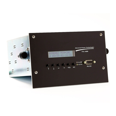
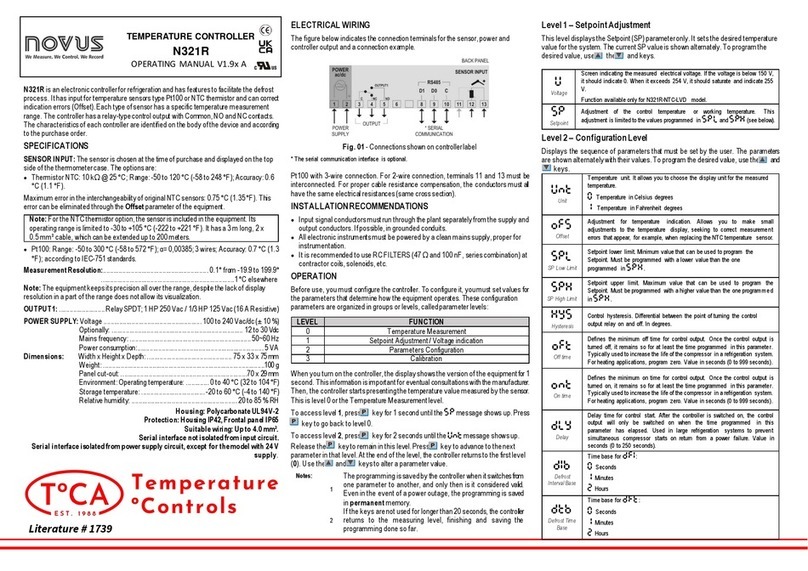
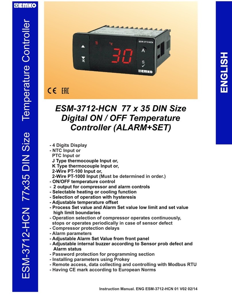
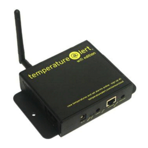
Advanced Power technologies TTC-1000 Installation instructions manual

V1.00, August 30, 2004
TTC-1000
3 Probe Transformer Temperature Controller
Instruction & Operation Manual
215 State Route 10, Building 2
Randolph, NJ 07869
Phone: (973) 328-3300
Fax: (973) 328-0666
Website: advpowertech.com
e-mail: [email protected]
Advanced Power Technologies

Table of Contents
V1.00, August 30, 2004
i
1 INTRODUCTION...........................................................................................1
2 PRODUCT DESCRIPTION............................................................................3
2.1 Controls & Indicators..................................................................................3
2.2 Connection Overview.................................................................................5
2.3 Specifications.............................................................................................6
2.4 Part Number Details...................................................................................8
3 INSTALLATION and CONNECTIONS...........................................................9
3.1 Mounting....................................................................................................9
3.2 Power Hookup..........................................................................................11
3.3 Temperature Probes................................................................................11
3.3.1 TTC-PROBE-01 Installation..............................................................12
3.3.2 TTC-PROBE-11 Installation..............................................................13
3.3.3 Magnetic Mount Probe (TTC-PROBE-02) Installation.......................13
3.3.4 Probe Lead Connections...................................................................16
3.4 Auxiliary CT Input for Calculated Winding Temperature ..........................18
3.5 Cooling Control and Condition Alarm Connections..................................19
3.6 Unit Alarm Connections ...........................................................................20
3.7 Telemetry Connections............................................................................21
3.7.1 RS-232 Terminal Connections..........................................................21
3.7.2 Analog Outputs.................................................................................22
3.7.3 RS-485 for DNP3.0 Communications ...............................................22
3.8 Optically Isolated Inputs...........................................................................24
3.9 Heater Connections .................................................................................25
4 SETTINGS...................................................................................................26
4.1 Programming Settings Through Front Panel............................................26
4.2 Programming Settings Through a PC ......................................................26
4.3 Settings for Calculated Winding Temperature..........................................29
4.3.1 CT RATIO.........................................................................................30
4.3.2 Rated Load .......................................................................................31
4.3.3 Hot Spot Rise over Top Oil ...............................................................31
4.3.4 Winding Rise Time Constant.............................................................32

Table of Contents
V1.00, August 30, 2004
ii
4.3.5 Calculated Winding Exponent Setting...............................................32
4.3.6 Checking Winding Temperature........................................................33
4.4 Setting Probe Names...............................................................................33
4.5 Temperature Set Points...........................................................................35
4.5.1 Setting Liquid Pickup and Drop Out Temperatures...........................38
4.5.2 Setting Calculated Winding Pickup and Drop Out Temperatures......39
4.6 LTC Condition Monitoring.........................................................................40
4.6.1 Setting LTCDIFF Set Point................................................................42
4.6.2 Setting LTCDIFF Pickup Timer.........................................................43
4.7 Load Pickup Set Points............................................................................43
4.7.1 Setting Load Pickup Set Point...........................................................45
4.7.2 Setting Load Pickup Timer................................................................46
4.8 Optically Isolated Input Settings...............................................................46
4.9 Programmable Logic Settings..................................................................48
4.9.1 Assigning Liquid Temperature Set Points.........................................49
4.9.2 Assigning Winding Temperature Set Points......................................51
4.9.3 Assigning LTCDIFF for LTC Condition Monitoring Alarm..................52
4.9.4 Assigning Load Pickup Set Points ....................................................54
4.9.5 Assigning IN1 and IN2 ......................................................................55
4.9.6 Assigning OUT1, OUT2, OUT3 and OUT4 .......................................56
4.9.7 Time Set Points.................................................................................58
4.9.8 Setting Output Timers.......................................................................60
4.9.9 Setting Output Invert.........................................................................60
4.9.10Application Examples........................................................................61
4.10 Setting Output Control With Alarm........................................................64
4.11 Alternate Fan Banks.............................................................................65
4.12 Auto and Manual Control......................................................................66
4.13 Setting Control of Unit Alarm................................................................67
4.13.1Device Alarm Setting.........................................................................68
4.13.2Temperature Probe Alarm Setting ....................................................68
4.13.3Manual Mode Alarm Setting..............................................................69

Table of Contents
V1.00, August 30, 2004
iii
4.13.4Winding Circuit Alarm Setting ...........................................................69
4.14 Setting Date and Time..........................................................................70
4.14.1Setting Time and Date Via the Front Panel.......................................71
4.14.2Setting Time and Date Via the PC....................................................72
4.15 Setting Password..................................................................................72
5 TELEMETRY OPTIONS..............................................................................74
5.1 Analog Outputs ........................................................................................74
5.2 DNP3.0 ....................................................................................................74
5.2.1 Setting BAUD Rate ...........................................................................76
5.2.2 Setting NODE Address .....................................................................76
5.2.3 Setting Remote Blocking...................................................................77
5.3 Telemetry Via RS232...............................................................................78
6 VIEW TEMPERATURES.............................................................................79
6.1 Single Probe.............................................................................................79
6.2 Dual Probe...............................................................................................80
Three Probe ....................................................................................................81
6.4 Single Probe With Calculated Winding.....................................................82
6.5 Dual Probe With Calculated Winding.......................................................83
6.6 Reset Min/Max.........................................................................................84
7 VIEW SETTINGS.........................................................................................85
7.1 View Settings Via Front Panel..................................................................85
7.2 View Settings Via PC...............................................................................85
8 STATUS ......................................................................................................88
8.1 View Status Via Front Panel.....................................................................88
8.2 View Status Via PC..................................................................................88
9 SETTING FILES..........................................................................................90
9.1 Upload Setting Files.................................................................................90
9.1.1 Upload Settings Using HyperTerminal..............................................90
9.1.2 Upload Settings Using Procomm......................................................94
9.2 Download Setting Files ............................................................................98
9.2.1 Download Settings Using HyperTerminal..........................................98

Table of Contents
V1.00, August 30, 2004
iv
9.2.2 Download Settings Using Procomm................................................101
10 DATA LOGGING .......................................................................................105
10.1 Data Storage ......................................................................................105
10.2 Data Points.........................................................................................106
10.3 Setting the Time Base ........................................................................106
10.4 Selecting Data Points.........................................................................107
10.4.1Add or Delete P1 From Log ............................................................107
10.4.2Add or Delete P2 From Log ............................................................107
10.4.3Add or Delete P3 From Log ............................................................108
10.4.4Add or Delete Calculated Winding From Log..................................108
10.4.5Add or Delete Load From Log.........................................................109
10.5 Retrieving Data Log............................................................................110
10.5.1Saving the Data Log as a Text File Using HyperTerminal...............111
10.5.2Saving the Data Log as a Text File Using ProComm......................114
10.6 Import to Excel....................................................................................117
11 DOWNLOAD PROGRAM UPDATES........................................................121
11.1 Download Firmware Using HyperTerminal.........................................122
11.2 Download Firmware Using Procomm .................................................126
12 SETTINGS WORKSHEETS ......................................................................132
12.1 Front Panel Setting Sheets.................................................................133
12.2 PC Setting Sheets..............................................................................147
13 DNP3.0 PROFILE DOCUMENT................................................................165

Table of Figures
V1.00, August 30, 2004
v
Figure 2. 1a: Front Panel, Panel Mount Version...................................................3
Figure 2.1b: Front Panel, NEMA 4 Version...........................................................3
Figure 2.2: Connection Overview..........................................................................5
Figure 3.1: Panel Mount Version Physical Dimensions and Panel Cutout............9
Figure 3.2: NEMA 4X Mounting..........................................................................10
Figure 3.3: Mounting Bracket..............................................................................10
Figure 3.4: Power Connections..........................................................................11
Figure 3.5: PROBE-01 Installation......................................................................12
Figure 3.6: PROBE-11 Installation......................................................................13
Figure 3.7: Magnetic Mount, Application of Thermal Compound........................14
Figure 3.8: Magnetic Mount, Side View ..............................................................15
Figure 3.9: Magnetic Mount, Application of RTV.................................................16
Figure 3.10: Probe Connections.........................................................................17
Figure 3.11: Temperature Probe Shield Grounding............................................18
Figure 3.12: Split Core CT Installation................................................................18
Figure 3.13: Auxiliary CT Connections................................................................19
Figure 3.14: Connections to Relay Outputs........................................................20
Figure 3.15: Connections to Relay Outputs in Models –3XX2............................20
Figure 3.16: Connections to Unit Alarm..............................................................21
Figure 3.18: Location of J2 RS-485 Bus Termination Jumper ............................23
Figure 3.19: Panel Mount and NEMA 4 RS-485 Connections ............................24
Figure 3.20: Four Wire RS-485 Connections......................................................24
Figure 3.21: Optically Isolated Input Connections...............................................25
Figure 4.1: Over Temperature Operation............................................................36
Figure 4.2: Under Temp Operation.....................................................................37
Figure 4.3: LTC Differential Set Point Operation.................................................40
Figure 4.4: Load Pickup Set Point Operation......................................................44
Figure 4.5: Input Set for LEVEL..........................................................................47
Figure 4.6: Input Set for PULSE .........................................................................47
Table 4.7: Operands...........................................................................................48
Table 10. 1: Maximum Records........................................................................105

Table of Figures
V1.00, August 30, 2004
vi

Warranty
V1.00, August 30, 2004
vii
All new products sold to customers are warranted against defects in design, materials, and workmanship for
the life of their use to the original end user. If it is determined that the new product defect is covered under
this warranty, Advanced Power Technologies, LLC (the “Company”) will repair, replace, or substitute an
identical unit at its own discretion to the customer at no charge. The Company requires the customer to ship
the unit back to the factory for diagnosis under all circumstances. In such event, the Company may, at its
own discretion, decide to provide the customer with a substitute unit which may be sent to the customer
either from the Company’s factory or from an authorized representative or distributor from their inventory. All
expenses related to the shipment of defective units back to the Company or the provision of a substitute unit
to the customer are the responsibility of the customer. This expense may include, but is not limited to,
freight, insurance, Customs clearance, and duties. All expenses related to the shipment of repaired units
back to customers (or the provision of a new unit to the customer) will be borne by the Company.
Product Upgrade Policy
From time to time, the Company makes product upgrades to add or enhance the performance of the
products. Customers of a particular product being issued an upgrade will be notified either by the Company
directly or through its authorized representatives or distributors. Customers who have purchased an annual
upgrade policy will receive all upgrades during the calendar year free of charge. Customers who did not
purchase the annual upgrade policy may purchase each unit upgrade individually. The annual upgrade
policy can be purchased at any time. Regardless of whether the upgrade policy is purchased, the Company
will make reasonable efforts to notify all customers of all available upgrades.
Equipment Repair and Warranty
Repair costs of products not covered under this warranty are paid for by customers. Customers are
responsible for the cost of shipping the products to the Company located at: 240 Dr. MLK Jr. Blvd., Newark,
NJ 07102, USA. All products repaired by the Company will continue to be warranted against defects in
material and workmanship for its installed life at the original end user.
Limitations
The Company's warranty does not extend to (A) The Company's products subject to (i) improper installation,
connection, operation, maintenance, or storage; (ii) accident, damage, abuse, or misuse; (iii) abnormal or
unusual operating conditions or applications outside the specifications for the product; (iv) a purpose or
application in any way different from that for which the products were designed; (v) repairs conducted by
persons other than the Company employees or an authorized representative or distributor; or (vi)
modifications made to the product by the customer or end user, (B) Equipment and products not
manufactured by the Company. Such equipment and products may be covered by a warranty issued by the
respective manufacturer. This warranty is in lieu of any other warranties, express or implied, including
without limitation, any warranty of merchantability or fitness for a particular purpose, and is in lieu of any and
all other obligations or liability of the Company. Under no circumstances shall the Company be liable for any
accidental or consequential damages or for any other loss, injury, damage, or expense of any kind including
loss of profits arising hereunder. To the extent any court, arbitration panel, or other governmental body of
competent jurisdiction shall declare any provision of this warranty invalid or unenforceable by reason of a
rule of law or public policy, all the other provisions hereof shall remain in full force and effect.

1V1.00, August 30, 2004
1 INTRODUCTION
The TTC-1000, 3 Probe Transformer Temperature Controller is a mission
specific programmable controller that measures up to three different probe
temperatures, load and calculated winding temperature. The user can program
four (4) independent outputs based on the state of pre-programmed temperature
set points, time set points, load set points or the outputs themselves. The
controller can measure any two of top oil, winding, LTC tank, or ambient
temperature to accuracy of ± 1 ºC and does not require calibration. Calculated
winding temperature is based on the methods of ANSI C57.91 and uses
measured top oil temperature and load current.
The outputs can be used to:
•Control cooling fans and pumps.
•Provide high temperature, LTC condition, and cooling system performance
alarms.
•Provide a trip output.
The TTC-1000 is substation hardened and designed to operate over a wide
temperature range of –35 to 85 ºC suitable for installation in outdoor cabinets.
The TTC-1000 contains many features including:
•Measures temperature from 0 to 160 ºC.
•Does not require calibration.
•Optional 0-1 or 4 - 20 mA analog outputs.
•Optional dual probe version for top oil and the heated well.
•Optional aux CT input for calculated winding temperatures.
•Load pickup set points for early activation of cooling based on sudden
increases in load.
•Differential temperature set point control for LTC condition monitoring.
•Universal probe kit includes thermo well fitting adapters and probe sleeves.
•Optional magnetic mount temperature probe when a thermo well is not
available.
•Reports Min and Max Temperatures, time stamped with date and time.
•Data logging.
•Periodic exercise of cooling fans.
•Automatic swapping of lead and lag fan banks.
•Four independent temperature set points per probe.

V1.00, August 30, 2004
2
•Cooling system performance monitor to alarm when cooling is commanded
but the current draw of the cooling fans or pumps is outside a specified
range.
•Four scheme logic programmable form C relay outputs, all trip duty rated.
•Dedicated programmable form B alarm relay.
•Remote/Local Comms through RS-232, no special software required.
•Flash memory for convenient firmware upgrades.
•Same unit operates from 38 to 160VDC or 120VAC and is immune to
reversal of battery voltage polarity.
•Available in either compact panel mount or a 304 Stainless Steel NEMA 4X
enclosure.
•Optional DNP3.0 Level 1 communications for reading analogs plus status
and remotely commanding cooling.
•Two optional optically isolated inputs for remote cooling control by SCADA,
reporting status from liquid level or sudden pressure alarms over DNP3.0, or
for selective blocking of outputs.
Each TTC-1000 is burnt-in for a total of 48 hours prior to shipping and comes
with a lifetime warranty.

V1.00, August 30, 2004
3
2 PRODUCT DESCRIPTION
The following section describes the front panel display, indicators, and switches,
connection points, mounting, physical size and panel cutout requirements
2.1 Controls & Indicators
Figure 2.1a and 2.1b show the front panel displays, indicators, and switches for
both panel mount and NEMA 4 versions:
Figure 2. 1a: Front Panel, Panel Mount Version
Figure 2.1b: Front Panel, NEMA 4 Version
!
!!
! "
""
"#
##
#$
$$
$
YES NO
ACTIVE
ALARM
RS-232
CLEAR WINDOW NO TEXTURE
Advanced Power Technologies
TTC-1000
65432
17 8
10
9
!
!!
! "
""
"#
##
#$
$$
$
YES NO
ACTIVE
ALARM
RS-232
CLEAR WINDOW NO TEXTURE
Advanced Power Technologies
TTC-1000
65432
17 8
10
9

V1.00, August 30, 2004
4
UP arrow button for navigating forward into menu categories and
increasing settings.
DOWN arrow button for navigating backward into menu categories and
decreasing settings.
LEFT arrow button used for moving to the next character to the left when
changing settings.
RIGHT arrow button used for moving to the next character to the right
when changing settings.
YES button is used to enter a menu category, request to change a setting,
and acknowledge a setting change.
NO button is used to leave a menu category or abort a setting change.
ACTIVE indicator is a green LED that illuminates when power is applied.
ALARM indicator is a red LED that illuminates whenever an alarm
condition is present. Alarms can be caused by a failure detected in the
electronics, or a broken temperature probe. In NEMA 4 mounting models,
this indicator will flash when using the light activated Min/Max reset
feature.
16 character by 2 line Liquid Crystal Display.
9 pin 15KV ESD protected RS-232 interface.
1
2
3
4
5
6
7
8
9
10

V1.00, August 30, 2004
5
2.2 Connection Overview
The Figure 2.2 describes the available connections.
Figure 2.2: Connection Overview
TTC-1000-XXX
10
2
1
3
4
2
3
4
5
6
7
8
9
12
11
10
9
8
7
6
5
1
2
3
1
TB1
TB2
TB3
COM
REF
TMP
Power In
38 to 160VDC or 120VAC
NC
COM
NO
NC
COM
NO
NC
COM
NO
NC
COM
NO
OUT4
OUT1
OUT2
OUT3
Temperature Probe
TTC-PROBE-YY-XXX
Ref Resistor
RTD
2
3
4
5
6
7
8
9
1
D
B
9
R
S
2
3
2
GROUND
Rx
Tx
N/C
N/C
N/C
RTS
CTS
WHT
RED
BLK
Probe #2 (optional)
12
11
NC
COM
ALARM
COM
REF
TMP
4
Aux CT
Connection
(Use CT
Supplied)
12
TB4
DO/
RI
DO/
RI
2-Wire RS-485
DNP 3.0
Interface
RTD
WHT
RED
BLK
Temperature Probe
TTC-PROBE-01-XXX
Ref Resistor
Probe #1
RTD
WHT
RED
BLK
Temperature Probe
TTC-PROBE-YY-XXX
Ref Resistor
Probe #3
NO

V1.00, August 30, 2004
6
2.3 Specifications
Power Supply Input Operating Range:
38 VDC to 160 VDC or 120VAC ±10%, 3 Watts max
Operating Temperature Range:
-35 °C to +85 °C
Liquid Temperature Measurement Range:
0 °C to +160 °C
LTC Differential Temperature Measurement Range:
-20 to +20 °C
Winding Temperature Measurement Range:
0 to 180 °C
Temperature Measurement Accuracy:
Average error over the entire measurement range of ± 1 °C; absolute error at
any temperature ± 1.5 °C
Current Measurement Range:
Instantaneous 0 to 10 A RMS. Measurement accuracy ± 3.5%. Using split core
CT provided.
Output Contact Rating:
30 amps make for 250 msec.
10 amps continuous at 230VAC
0.4 amps break at 160VDC. See Section 4.3 for note on breaking under load
Alarm Contact Rating:
0.15 amp continuous at 160VDC
Analog Output:
Selectable, 0 to 1 mA or 4 to 20 mA current source referenced to chassis
ground
Maximum load 9,500 ohms for 0 to 1 mA and 450 ohms for 4 to 20 mA
Dimensions:
Panel Mount: 5.32” W x 2.61” H x 6” D. Aluminum

V1.00, August 30, 2004
7
NEMA 4X: 10” H x 6” W x 3.25” D. 304 Stainless Steel
Surge Withstand/Fast Transient:
Relay outputs, and station battery inputs: ANSI C37.90.1
EMI Withstand:
ANSI C37.90.2
Dielectric Withstand:
1500 VDC for 10 seconds
Electrostatic Discharge:
IEC 801-2
Timers:
Output and Load Pick Up Timer: 0 to 255 seconds (actual minimum delay 32
msec)
Optically Isolated Inputs:
External wetting required. Picks up between 38 and 160 VDC. Maximum input
160 VDC.

V1.00, August 30, 2004
8
2.4 Part Number Details
NOTE: Consult the factory for other options not listed.
TTC- PROBE- 0 t -zzz
Probe lead length, zzz=10 to 250 ft
1
Universal Thermowell Probe 2
Magnetic Surface Mount Probe 0
0
1 1
Universal Well Probe Liquid Tight Rdy
TTC- 1000- w x y
Panel Mounting 0
NEMA 4X Enclosure 3
Single analog output
Dual analog output 2
3
1
2
3
4
Single Probe
Dual Probe
AUX CT, Single Probe
AUX CT, Dual ProbeRS485w/Dnp3 Level 1 5
No telemetry outputs 0
z
1
2
4 form C Outputs, No inputs
6 form C Outputs, No inputs
4 form C Outputs, 2 inputs
36 form C Outputs, 2 inputs
NEMA 4X w/Heater 4
RS485w/Dnp3 Level 1 & sngl analog output (NEMA only) 6
RS485w/Dnp3 Level 1 & dual analog outputs (NEMA only) 7 7 AUX CT, Three Probe
6Three Probe

V1.00, August 30, 2004
9
3 INSTALLATION and CONNECTIONS
The following section gives information on hookup of power, temperature probes,
split core CT, outputs, optically isolated inputs, analog outputs along with
connections to RS232 and RS485 for DNP3.0 communications.
3.1 Mounting
There are two mounting configurations available. Panel Mount is intended for
installation inside the transformer control cabinet and NEMA 4X for mounting
either inside or outside the control cabinet. Figure 3.1 shows the outline & cutout
required for panel mounting.
Figure 3.1: Panel Mount Version Physical Dimensions and Panel Cutout
Set
Screw
!
!!
! "
""
"#
##
#$
$$
$
YES NO
ACTIVE
ALARM
RS-232
CLEAR WINDOW NO TEXTURE
Advanced Power Technologies
TTC-1000
5.70 in.
2.83 in.
6.10 in.
2.63 in.
0.32 in.
5.35 in.
2.65 in.
0.52 in.

V1.00, August 30, 2004
10
Figure 3.2 shows the outline of the NEMA 4X enclosure. A mounting bracket,
P/N:80001000126, suitable for retrofit or new applications is shown in Figure 3.3.
The bracket is constructed from 1/8” THK 5052 Aluminum.
Figure 3.2: NEMA 4X Mounting
Figure 3.3: Mounting Bracket
0.000
2.375
9.250
14.000
0.000
5.000
6.000
7.000
12.628
13.375
1.000
2.122 7.122
8.250
Ø 0.516
10 PLACES
4.250
10.753
0.000 2.000
Ø 0.312
4 PLACES
0.625
45.0°
2 PLACES
3/4 inch DIA
2 PLACES
Lexan Window
0.000
0.00 1.50 3.00 4.50
1.500
3.312
13.0”
O
blong
0.312 X 0.500
5.00
Probe Cable
Fitting, Included
Liquid-Tight
Cable Strain Relief

V1.00, August 30, 2004
11
3.2 Power Hookup
The TTC-1000 can be powered from either DC substation battery between
voltages of 38 to 160 VDC or from AC voltage of 120 ±10% VAC. On panel
mount units (Figure 3.4a) power is connected to terminals 1 and 2 of barrier style
terminal block TB1. On NEMA units (Figure 3.4b) power is connected to
terminals 1 and 2 on TB-3. The TTC-1000 is not sensitive to polarity because it
uses a bridge rectifier on the power input. This feature eliminates the risk of
damage due to the reversal of power applied to this input.
Figure 3.4: Power Connections
NOTE:
1. It is strongly recommended that the chassis of the panel mount unit or
NEMA 4 enclosure be bonded to ground. It is especially important to
ground the unit when operating from 120 VAC.
2. For NEMA 4 units it is strongly recommended that the external ¼-20
ground stud be utilized for proper grounding.
3. When powering from AC substation service, it is essential that
appropriate surge suppression is installed on the AC mains feeding the
unit.
WARNING:
NEVER CONNECT POWER TO TERMINALS DESIGNATED FOR THE AUX
CT. SERIOUS DAMAGE WILL OCCUR.
3.3 Temperature Probes
The TTC-1000 can be equipped with up to three probes. Universal thermowell
probe types TTC-PROBE-01 and TTC-PROBE-11 are each provided with three
12
Power
34
Aux CT
TB1
1234
PowerAux CT
TB3
TB2
a) Panel Mount b) NEMA 4

V1.00, August 30, 2004
12
thermometer well adapter fittings: 7/8-UNF (ANSI/IEEE C57 thermometer well),
½-NPT and ¾-NPT and three probe sleeves: 0.481, 0.625 and 0.675 OD.
Temperature probes are interchangeable and do not require calibration. The
temperature probes and measurement circuitry are intrinsically accurate to the
stated accuracy specification. The probe leads are connected to a plug gable
compression style terminal block. A terminal block is supplied with each unit and
plugs into TB2.
3.3.1 TTC-PROBE-01 Installation
Probe type TTC-PROBE-01 is provided with a strain relief that seals the
thermometer well and holds the probe from pulling out of the well. Figure 3.5
shows the outline drawing for this probe type.
Figure 3.5: PROBE-01 Installation
To install the probe into the thermo well:
1. Select the appropriate thermo well adapter fitting and either wrap the male
threads with Teflon tape or coat with suitable pipe dope compound. Once
the male threads are prepared, thread the adapter fittings into the thermo
well.
2. If the probe well’s ID is greater than 0.390 select the appropriate probe
sleeve and slide over the probe. Tighten the set screw with the
accompanying Allen Key.
3. Slide the probe into the thermo well.
4. Ensure that the snap elbow fitting is fully open. Apply Teflon tape to the
male threads of the snap elbow fitting. Thread the snap elbow into the
female threads of the thermo well adapter fitting.
Probe Cable Brass Fittings
(Included)
Snap Elbow
Probe
Thermometer Well
Probe
Sleeve
(Included)
Other manuals for TTC-1000
2
Table of contents
Other Advanced Power technologies Temperature Controllers manuals
