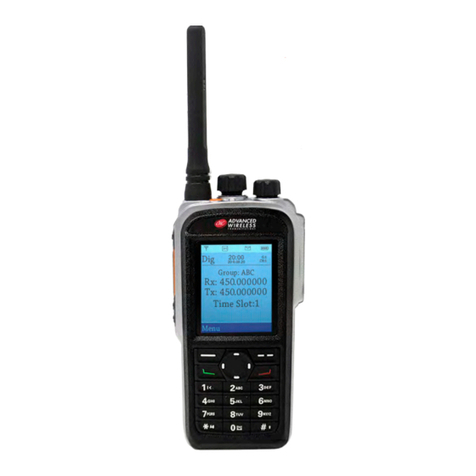
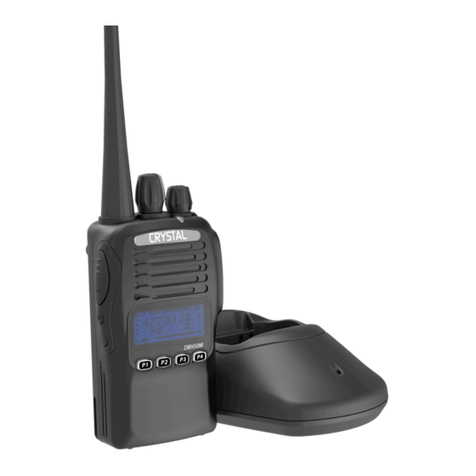
Advanced Wireless Communications AWR-D7000 User manual

User Manual
AWR-D7000
Digital Portable Radio

Thank you for purchasing this AWR-D7000 Digital two-way radio by
Advanced Wireless Communications (AWC). This product is designed
and developed according to FCC/IC/EU and advanced international
standards.
Our products are tested using strict and rigorous test procedures with
advanced test instruments and equipment to internationally recognized
standards.
Thank you!
This manual should be read to ensure that the user understands the
operation of the AWR-D7000. Please read the Safety Information
Manual before use.

Safety Instructions
Please observe the following safety tips to prevent re, accidents,
personal injury or equipment damage.
• Do not modify the radio or its charger in any way.
• Do not expose the radio to direct sunlight for extended periods of
time, leave near heaters or other heat sources.
• Do not store or use unprotected radios for prolonged periods in
areas of high dust or excessive moisture.
• Users may experience signal interference if the unit is used near
devices such as TV or electric generators.
• If the unit emits smoke or you notice a strange smell, immediately
turn o the power, and send it to the closest repair station.
• The radios are small but contain high power components. It is not
uncommon to notice slight warming of the handset. This is normal
and the unit may be continued to be used.
If there is any problem with the radio, please contact Advanced
Wireless Communications or your local distributor.

Turn on
Turn the Volume/Power knob clockwise to turn the radio on.
(Some radios are programmed to emit a tone when powered on).
Turn o
Turn the Volume/Power knob counter clockwise to turn the radio o,
you will hear a sound when the radio is turning o.
Volume adjustment
Press and hold down the squelch key o momentarily to hear
a continuous beep and turn the volume/power knob to adjust.
Three way to choose channel
1 Channel knob: rotate the “channel control” to choose the
needed channel.
2. Channel button: choose the channel you need.
Transmit and receive
Press PTT button, the radio will enter the transmit state, the red light
will turn on, the LCD display (if equipped) will indicate transmit.
Release PTT button, the radio will enter the receive state, the green
light will turn on when receiving voice / data, and the LCD display (if
equipped) will indicate receive.

Advanced Wireless Communications Radio
Quality Warranty and Liability
The warranty range and limitation
Advanced Wireless Communications (AWC) is committed to quality
and stands behind its products. AWC will, during the warranty period
specied for each product, repair or replace components that fail as a
result of poor workmanship or materials. This warranty does not cover
improper use or intentional damage.
The warranty policy does not include the following conditions:
1. Defects or damages caused by working in abnormal or unusual
situations.
2. Defect or damages caused by misuse, accident, or water
submersion.
3. Defect or damages caused by unauthorized installation, repair,
tampering or adjustment.
4. Warranty does not extend to cosmetic scratches or damages as a
result of normal use or misuse.
5. This warranty is void if:
(a) The product information label on the back aluminum case
is removed, or if the serial number is tampered with,
changed or cannot be identied.
(b) If the battery case is damage, tampered with or unsealed.
General Items
This warranty policy establishes the liability limits for which AWC is
responsible. AWC has the right to decide, in their sole discretion,
whether to repair, replace, or refund the purchase price of any
equipment subject to this warranty. There are no other options
available under this warranty. This express warranty is the complete
agreement. OTHER THAN AS EXPRESSLY SET OUT IN THESE
TERMS OR ADDITIONAL TERMS, NEITHER AWC NOR ITS
SUPPLIERS OR DISTRIBUTORS MAKE ANY SPECIFIC PROMISES
ABOUT THE SERVICES OR PRODUCTS.

CONTENTS
Unpacking and device check.............................................................. 1
Accessories .................................................................................... 1
Battery information ............................................................................. 2
Battery protection ........................................................................... 2
Battery usage ................................................................................. 3
Battery charge ................................................................................ 3
Preparation......................................................................................... 4
Installing the battery ....................................................................... 4
Assemble the antenna.................................................................... 4
Assemble the belt clip..................................................................... 5
Disassemble the belt clip................................................................ 5
Insert the earphone ........................................................................ 5
Function key ....................................................................................... 6
Charging the battery....................................................................... 7
Charger indicator............................................................................ 7
LED indicator of transceiver ........................................................... 7
Function and basic operation ............................................................. 8
Turning your radio on and o.......................................................... 8
Switch channel ............................................................................... 8
Push-to-talk operation .................................................................... 8
Digital channel information ................................................................. 12
Time out timer (TOT) ...................................................................... 12
Single call, group call, all call.......................................................... 13
CTCSS / CDCSS............................................................................ 13
Tail tone elimination........................................................................ 14
Power ............................................................................................. 14
Digital mode setting............................................................................ 15
Safety information............................................................................... 16

Unpacking and device check
Please take the radio out of the package carefully, and before
disposing of the package material, we advise you to check the
accessories according to the following list. If any part is lost or
damaged, please request a claim latter from the shipper or supplier.
Accessories:
Items Quantity
Antenna 1
Belt clip 1
Power supply 1
Battery 1
Charger 1
Lanyard 1
Instruction manual Available at www.advancedwireless.com
Warranty card Available at www.advancedwireless.com
1

Battery information
Battery protection
Advanced Wireless Communications’ (AWC) radios use lightweight,
environmentally friendly lithium-ion batteries as a power source. The
following battery tips will help you to get the best performance and
prolong the battery life of your equipment.
1. Be sure to use the original AWC charger to charge the battery.
2. When charging radios, please power o the radios to ensure
battery can be fully and eectively charged.
3. New, uninstalled batteries can be stored for long period, but should
be stored in a cool, dry place. (These should be recharged once
every three months to maintain the battery’s electrical properties,
otherwise it will be damaged and will not function properly).
4. New batteries need to be fully charged before use.
5. Use only the battery charger and power supply specied by AWC.
Use of non-authorized charging systems will void the warranty of
both the battery and the equipment.
6. Avoid extreme temperatures as this will eect capacity of the
battery.
7. The battery cannot be stored in hot or cold places, otherwise it will
reduce battery capacity and useful life. The battery should always
be stored at normal temperature, and radios equipped with cold
batteries may temporarily not work, even if fully charged.
8. Do not let the metal stripes on the battery come into contact with
metal objects (such as metal benches, pins, etc) as this may cause
the battery to short circuit.
9. Always dispose of old or damaged batteries in accordance with
local recycling laws.
10. NEVER discard or expose batteries in a re, this may result in an
explosion and serious injury or death.
2

Battery information (continued)
Battery Usage
1. Do not use, install or attempt to charge damaged batteries.
2. Do not use batteries in any other equipment other than that which it
is designed for.
3. Battery charging time varies and is determined by the remaining
capacity of the battery and the battery and charger type. The
battery can be repeatedly charged and discharged more than
300 times, but they will age with use. Aging will occur quicker when
batteries are used for short periods and then recharged. Batteries
should be allowed to fully discharge before charging to prolong
battery life.
4. Batteries that are stored and unused discharge over time.
Battery charge
1. The battery may be installed in the charger on the radio or alone.
Please use the provided charger power supply with the charger.
2. The charger indicator shows the charge state:
Indicator Current State
Red light ashing Waiting for charge
Red light glows During charging
Green light glows Charge complete
3

Preparation
Installing the battery
Assemble the antenna
Assemble: Align the battery with the radio
chassis, push forward and down until the battery
clicks in place.
Disassemble: Lift battery catch on bottom of
battery, lift up and pull away from chassis.
Insert antenna’s threaded connector into radio’s
antenna connector. Thread clockwise until snug.
Do not over tighten.
4

Preparation
Assemble the belt clip
Disassemble the belt clip
Insert the earphone
Assembly: Attach belt clip using the provided
screws by aligning screws with threaded holes in
chassis.
Disassemble: Unscrew the screws holding the
belt clip and remove belt clip from chassis.
Open the rubber cover to insert the Earphone .
5

Function Key
6

Charging the Battery
Use only the charger and battery specied by Advanced Wireless
Communications. Charger LED will indicate the charging process.
Charger Indicator
Indicator Charge Status
Red ash Standby
Red glows Charging
Green glows Fully charged
LED Indicator of Transceiver
Indicator Charge Status
Green glows 2-3S Power-on cycle
Green glows Receiving signal
Green ash Received
Red glows Transmitting
Red ash Battery low will be indicated by
the red LED ashing and an
audible beep. Please charge
or replace the battery as soon
as possible to ensure normal
operation.
7

Function and basic operation
Turning your radio on and o
Power on: Turn selector (power switch/ volume control knob)
clockwise. Click will be heard when selector turns the radio on. If
programmed, a power-on tone will be heard and the radio will enter the
receive state.
Power o: Turn selector (power switch/ volume control)
counterclockwise until a click is heard. This indicates that the radio is
powered o.
Switch channel
When you need to make a call on a specic channel, rotate the
channel knob to the desired channel. If the channel broadcast function
is enabled, the channel number will be announced locally. If a channel
has not been populated via programming, a continuous tone will be
heard from the radio.
Push-to-talk operation
Select the desired channel with the channel selector.
Transmit: Hold the radio in a vertical position approximately 2.0 cm
(1.0 inches) from your lip. Press the PTT and speak.
Receive: The LED indicator will light green when a signal is
received and the speaker will emit audio. Adjust the volume control
knob for a comfortable level.
8

Key Functions
K1
Short
Press
Non-functional; Emergency alarm; Cancel emergency alarm; Voice
control, Power switch, Steady stale monitoring [Simulation], Steady
cancel mute [Simulation]; Scanning; (DMR); one click call 4 (DMR);
broadcast local ID (number); broadcast channel number; broadcast
power; broadcast battery power; broadcast channel type; area switch-
ing;
Long
Press
No function; emergency alarm; cancel emergency alarm; voice control;
power ewitching; steady state monitoring [eimulation]; transient moni-
toring [simulation]; steady etate cancel squelch [simulation]; traneient
cancel squelch [eimulation]; Network; One-key call 1 (DMR); One-key
call 2 (DMR); One-key call 3 (DMR); One-key call 4 (DMR); Broadcast
local ID (number); Broadcast channel number; Battery power; broad-
cast channel type; area switching;
K2
Short
Press
Non-functional; Emergency alarm; Cancel emergency alarm; Voice
control; Power switch; Steady state monitoring [Simulation]; Steady
cancel mute [Simulation]; Scanning; (DMR); one-click call 4 (DMR):
broadcast local ID (number); broadcast channel number; broadcast
nower· broadcast batterv newer· broadcast channel tvne· area aw-
itchinn·
Long
Press
No function; emergency alarm; cancel emergency alarm; voice control;
power switching; steady state monitoring [simulation]; transient moni-
toring [simulation]; steady state cancel squelch [simulation]; transient
cancel squelch [simulation]; Network; One-key call 1 (DMR); One-key
call 2 (DMR); One-key call 3 (DMR); One-key call 4 (DMR); Broadcaat
local ID (number); Broadcaat channel number; Battery power; broad-
cast channel type; area switching;
K3
Short
Press
Non-functional; Emergency alarm; Cancel emergency alarm; Voice
control; Power switch; Steady state monitoring [Simulation]; Steady
cancel mute [Simulation]; Scanning; (DMR); one-click call 4 (DMR);
broadcaet local ID (number); broadcast channel number; broadcast
power; broadcast battery power: broadcast channel type; area switch-
ing:
Long
Press
No function; emergency alarm; cancel emergency alarm; voice control;
power switching; steady elate monitoring [simulation]: transient moni-
toring [simulation]; eteady elate cancel squelch [simulation]; transient
cancel squelch [simulation); Network; One-key call 1 (DMR); Ona-key
call 2 (DMR); One-key call 3 (DMR); One-key call 4 (DMR); Broadcast
local ID (number); Broadcast channel number; Battery power; broad-
cast channel type; area switching;
TK/
Emergency
(Orange)
Short
Press
Non-functional; Emergency alarm; Cancel emergency alarm; Voice
control; Power switch; Steady state monitoring [Simulation]; Steady
cancel mute [S1m11lat1on]; Scanning; (DMR); one-click call 4 (DMR);
broadcast local ID (number); broadcast channel number; broadcast
power; broadcast battery power; broadcast channel type; area switch-
ing;
Long
Press
No function; emergency alarm; cancel emergency alarm; voice control;
power switching; steady state monitoring [simulation]; transient moni-
toring [simulation]; steady etate cancel squelch [simulation]; transient
cancel squelch [simulation]; Network; One-key call 1 (DMR); One-key
call 2 (DMR); One-key call 3 (DMR); One-key call 4 (DMR); Broadcast
local ID (number); Broadcast channel number; Battery power; broad-
cast channel type; area switching;
9

Functional key
Non-functional
No function programmed (invalid key, error beep).
Emergency alarm
Pressing this button allows the user to initiate an emergency alarm,
which is typically a top key function. (Only short keys are supported,
long keys must be associated with emergency alarm o).
Cancel emergency alarm
Pressing this button allows the user to stop an emergency alarm,
which is typically a top key function. (Only supports long key, short key
must be associated with emergency alarm on).
Steady state (analog)
If not automatically reset, press the key during receive. Press the key
again to exit the monitor state.
Steady cancel squelch (analog)
Press key to disable noise squelch when squelch is open. Press again
to cancel and exit noise squelch.
Transient cancel squelch (analog)
Press to disable noise squelch when in transient squelch mode.
Release key to exit noise squelch.
10

Scanning
Press this button to enable or disable the scan function.
When scan is enabled, a beep will sound and the LED will ash green
to indicate that the radio is in scan. Pressing the scan key again will
result in two beeps to indicate scan mode was exited.
One key calling 1-4 (DMR)
One key calling function including SMS, Voice call. To enable the
feature, press the programmed key, then hold the PT T to launch the
call.
11

Digital Channel Information
Function: Set digital channel parameters.
Local number: The unique unit identier used to identify an individual
radio/ radio user.
Group call timer: Maintains group call for the period of the timer for
the group call users.
Private call timer: Maintains the private call for the period of the timer
so the two units in the call do not drop out of private call until timer
expires.
Transmit pre-carrier time: The transmitter carrier period before data
or control information is sent to insure information will be sent properly.
It is to insure that other receivers have been captured before data
is sent. It should be carefully set to support the needs of the system
since it does consume channel resources. For example, time may be
extended to insure scanning radios stop on channel.
Voice delay: This parameter denes the overall voice delay when the
transceiver initiates voice communication.
Time out timer (TOT): Ensures that a channel is not used for an
extended period that may consume resources and cause damage to
the radio.
Timeout: The maximum amount of time allowed for continuous
transmit. The radio will emit a local warning tone and will stop transmit
when programmed time is met.
Early warning time: A pre-alert tone may be set to tell the user that
the timeout time is about to be met. The alert will sound locally.
12

Retransmission time: This is the time set in programming that
denotes the period from when the time out timer expires to when the
user may transmit again. The radio will not be able to transmit until this
time expires. Pressing the PTT will sound a warning tone.
Reset time: If the PTT is released before the timeout timer expires,
the timer restarts the count once the PTT is pressed again.
Single call, Group call, All call
Single call (private / individual call): A call made by one user to
another user.
Group call: A group call is made by one user to many users in the
same group.
All call: A user makes a call to All users. All Calls are special groups
that encompass all the users on a channel. It is is considered a high
level call meant for special uses and users. The All Call group
ID is 16777215.
CTCSS / CDCSS
CTCSS features: CTCSS is sub-audible signaling used in analog
operation to limit users to those with matching signaling. Reduces
interference on a channel by selectively opening the radios audio gate.
CDCSS features: CDCSS uses digital signaling in analog operation
to limit users to groups with like signaling.
13

Tail tone elimination (squelch tail)
Used to stop the noise heard in a receiving radio when a transmitting
radio stops transmitting by reversing the phase of the analog sub-
audible signaling.
Power
Power level denes the RF output level emitted by the radio in
transmit.
The power level should be set for the appropriate use to insure range,
call quality, and battery life.
Value range: low power/ high power
14
Other manuals for AWR-D7000
1
Table of contents
Other Advanced Wireless Communications Radio manuals
