Advanipc AES-1210 Series User manual
1
1.
AES‐1210Series
UserManual

2
Copyright
The documentation and the software included with this product are copyrighted 2014 by
Advanipc Technology Corporation. Advanipc Technology Corporation reserves all the
right in the products described in this manual. No part of this manual may be reproduced
or copied without the prior written permission of Advanipc Technology Corporation.
Acknowledgements
Microsoft Windows and MS-DOS are registered trademarks of Microsoft Corp. All
other product names or trademarks are properties of their respective owners.
Printed in Taiwan
AES-1210 Series User Manual
Edition 1.2
March/ 2015

3
Packing List
Before powering up the system, check that the items listed below are included and in
good condition. If any item does not accord with the table, please contact your dealer
immediately.
AES-1210 series system x 1
Phoenix Terminal Block 2-Pin Female x 1( only for DC input by 2-Pin models)
Rubber stand x 4
CD x 1 (Drivers and User Manual)
Optional parts:
DC Adapter 50W or 60W with 2P Terminal Block and power cord
DC Adapter 50W with DC-Jack and power cord
Wall Mount bracket x 2 with screws x 4

4
Safety Instructions
1. Read these safety instructions carefully.
2. Read this User Manual before the first time to power on your system.
3. Disconnect this equipment from any AC/DC outlet or DC source before
cleaning. Do not use liquid or spray detergents for cleaning.
4. Put this equipment on a reliable surface during installation. Dropping it or letting it
fall may cause damage.
5. The openings on the enclosure are for wall mounting. If the system doesn’t need
wall mounting, it is better for chassis to use rubber feet on the down side. Please
cover the opening or cancel the opening if system is working in the high humidity
environment.
6. Make sure the voltage of the power source is correct before connecting the
equipment to the power outlet.
7. All cautions and warnings on the equipment should be noted.
8. If the equipment is not used for a long time, disconnect it from the power source to
avoid damage by transient overvoltage.
9. Never pour any liquid into an opening. This may cause fire or electrical shock.
10. Never open the equipment. For safety reasons, the equipment should be
opened only by qualified service personnel.
11. If one of the following situations arises, get the equipment checked by service
personnel:
The packing carton or PE forms are damaged.
Liquid has penetrated into the equipment.
The equipment has been exposed to moisture.
The equipment does not work well, or you cannot get it to work according to
the user manual.
The equipment has been dropped and damaged.
The equipment has obvious signs of breakage.
AES-1210 Series User Manual

5
Contents
Chapter 1
System Overview ....................................7
1.1 System View ................................................................................................. 8
1.2 System Bottom Plate .......................................................................................9
1.3 System Wall Mount Solution..........................................................................10
1.4 System Dimension.........................................................................................11
Chapter 2
System Installation ..................................12
2.1 How to operate the System ....................................................................... 13
2.1.1 DC-IN by 2-Pin Phoenix Connector ..................................................... 13
Figure 2.1.1-1 DC Power Input ....................................................... 13
2.1.2 DC-IN by DC-Jack ............................................................................... 13
Figure 2.1.2-1 DC-Jack ................................................................... 13
2.1.3 Optional DC Power Sources................................................................ 14
Figure 2.1.3-1 DC Adapter by 2-Pin................................................ 14
Figure 2.1.3-2 DC Adapter by DC-Jack........................................... 14
2.1.4 Power-On System by Switch ............................................................... 14
Figure 2.1.4-1 System Switch.......................................................... 14
2.2 RS-232 COM Port Connectors .....................................................................15
Table 2.2-1 Pin List of COM1/COM2.................................................15
2.3 VGA ..........................................................................................................15
2.4 HDMI .........................................................................................................15
2.5 Ethernet LAN Connectors.............................................................................16
2.6 USB Ports and Audio....................................................................................16
2.7 mSATA and DRAM .......................................................................................17
2.8 SATA DOM ...................................................................................................17
Chapter 3
SBC-210 IMB .............................................18
3.1 Introduction ...................................................................................................19
3.1.1 Specifications.......................................................................................20
3.1.2 Motherboard Layout............................................................................. 21
3.1.3 I/O Panel.............................................................................................. 23
3.2 Installation..................................................................................................... 24
3.2.1 Screw Holes......................................................................................... 24
3.2.2 Pre-installation Precautions................................................................. 24
3.2.3 Installation of Memory Modules (DIMM).............................................. 25
3.2.4 Expansion Slots................................................................................... 26
3.2.5 Jumpers Setup..................................................................................... 27
3.2.6 Onboard Headers and Connector........................................................ 29
3.2.7 Driver Installation Guide ...................................................................... 33
3.3 UEFI Setup Utility.......................................................................................... 34
3.3.1 Introduction.......................................................................................... 34
3.3.1.1 UEFI Menu Bar.................................................................... 34
3.3.1.2 Navigation Keys................................................................... 35
3.3.2 Main Screen......................................................................................... 36
3.3.3 Advanced Screen................................................................................. 37
3.3.3.1 CPU Configuration............................................................... 38
3.3.3.2 Chipset Configuration.......................................................... 40
3.3.3.3 Storage Configuration.......................................................... 42
3.3.3.4 Intel(R) Smart Connect Technology.................................... 43
3.3.3.5 Super I/O Configuration....................................................... 44

6
3.3.3.6 ACPI Configuration.............................................................. 45
3.3.3.7 USB Configuration............................................................... 46
3.3.4 Hardware Health Event Monitoring Screen.......................................... 47
3.3.5 Security Screen.................................................................................... 48
3.3.6 Boot Screen......................................................................................... 49
3.3.7 Exit Screen........................................................................................... 51
3.4 Software Support.......................................................................................... 52
3.4.1 Install Operating System...................................................................... 52
3.4.2 Support CD Information....................................................................... 52
3.4.2.1 Running Support CD ........................................................... 52
3.4.2.2 Drivers Menu....................................................................... 52
3.4.2.3 Utilities Menu....................................................................... 52
3.4.2.4 Contac Information.............................................................. 52

7
Chapter
1
System Overview

8
1.1 System View
AES-1210 series are with Power Switch, Power LED, HDD LED and 4 USB 2.0 on front
bezel.
AES-1210 series are with rich I/O. It has DC input by DC-Jack or by 2-pin connector, 2x
USB 2.0, Line Out, 2x USB 3.0, 2LAN, dual display VGA/HDMI and Wi-Fi feature by
option.
9
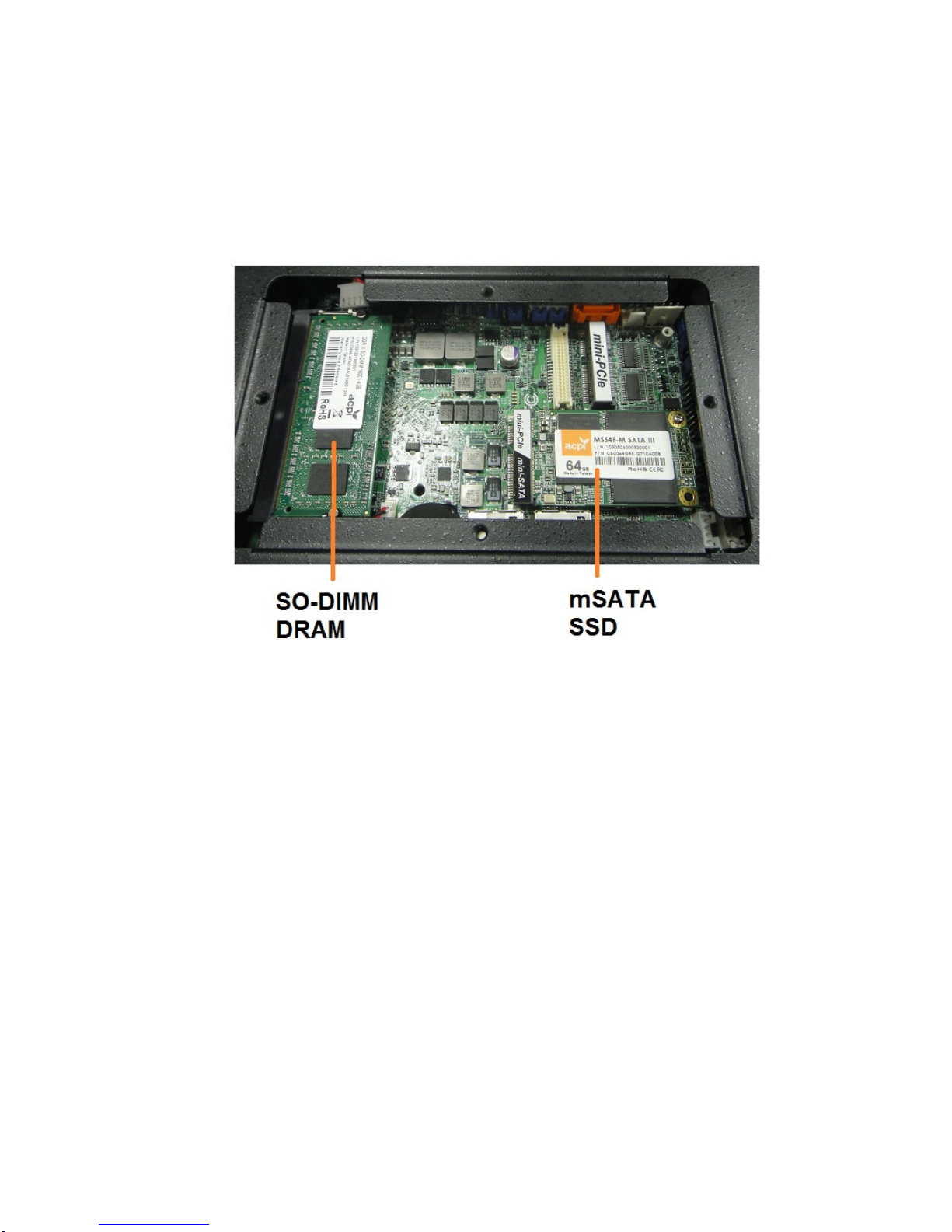
1.2 System Bottom Plate
System equips a bottom plate on the down side of chassis. It is friendly for DRAM,
mini-PCIe full-size mSATA module and mini-PCIe half-size devices installation and
replacement.
10
1.3 System Wall Mount Solution
System equips an optional wall mount bracket to hang AES-1210 on the wall. There are 4
holes from these two wall mount brackets to fix system on the suitable location.

11
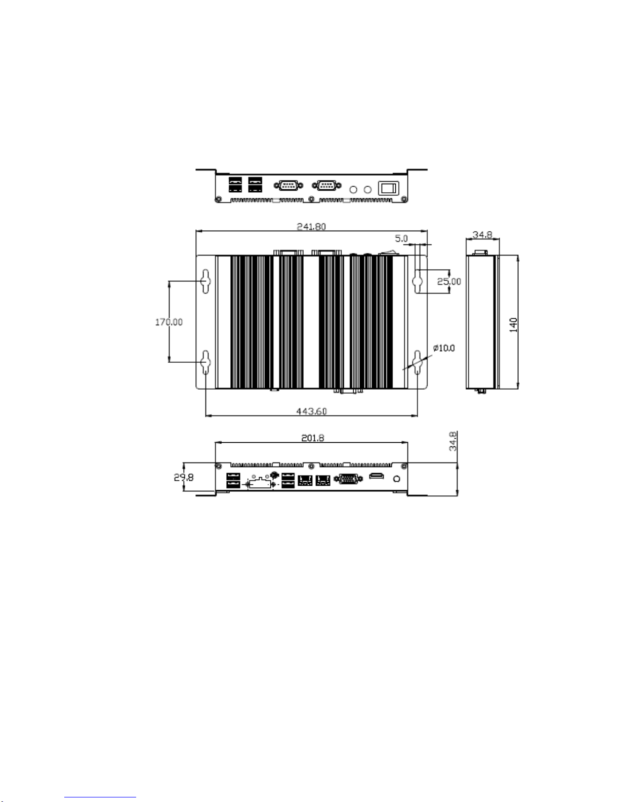
1.4 System Dimension
The dimension of AES-1210 is 202mm (W) x 140mm (D) x 30mm (H).

12
Chapter
2
System Installation
13
2.1 How to operate the System
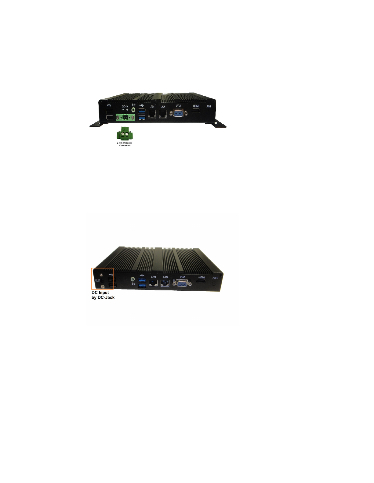
2.1.1 DC-IN by 2-Pin Phoenix Connector
System equips a male phoenix 2-Pin terminal block for DC power input. In the accessory
box, we provide a female 2-Pin phoenix connector showing as Figure 2.1.1-1. The DC
voltage input range is from DC +9V to +36V.
Figure 2.1.1-1 DC Power Input
2.1.2 DC-IN by DC-Jack
Besides the 2-Pin terminal block for DC source input, system also equips a DC-Jack
showing as Figure 2.1.2-1 for DC power input. The DC voltage input range is from DC +9V
to +36V.
Figure 2.1.2-1 DC-Jack

14
2.1.3 Optional DC Power Sources
We offer two kind of optional DC power sources for AES-1210 series. One is with 2-Pin
phoenix connector which is the most popular for industrial application. Another is with
DC-Jack which is the most popular for commodity devices. Both are showed as Figure
2.1.3-1. And Figure 2.1.3-2.
Figure 2.1.3-1 DC Adapter by 2-Pin Figure 2.1.3-2 DC Adapter by DC-Jack
2.1.4 Power-On System by Switch
Before you are going to power-on system, please check your DC source is with correct
connection.
Press the System Switch on front bezel left side showing as Figure 2.1.4-1 to power-on
system. You could press system switch again to turn system off.
Figure 2.1.4-1 System Switch

15
2.2 RS-232 COM Port Connectors
System provides two serial ports COM1 and COM2 on front bezel. COM1 supports
RS232/422/485 and COM2 supports RS232.
COM1RS‐232/422/485PinDescriptionList
COM2RS‐232PinDescriptionList
Pin No.
RS-232 RS-422 RS-485
1DCD TX‐RTX‐
2RxD RX+ N/A
3TxD TX+ RTX+
4DTR RX‐N/A
5GND GND GND
6DSR N/A N/A
7RTS N/A N/A
8CTS N/A N/A
9NA/+5V/+12V N/A N/A
Table 2.2-1 Pin List of COM1/COM2
2.3 VGA
System supports a VGA output by D-SUB 15-Pin connector.
2.4 HDMI
System supports a HDMI connector for display output.

16
2.5 Ehernet LAN Connectors
System supports two 10/100Mbps Ethernet port by two RJ-45 LAN connectors.
2.6 USB Ports and Audio
System provides 2 x USB 3.0, 2 USB 2.0 type A ports and one line-out audio port on rear
I/O. System offers 4 x USB 2.0 type A ports on front bezel.

17
2.7 mSATA and DRAM
System provides friendly SO-DIMM DRAM and mSATA SSD installation, maintenance.
2.8 SATADOM
System provides low profile SATADOM for space limitation.

18
Chapter
3
SBC-210 IMB

19
3.1 Introduction
Thank you for purchasing the 3.5” SBC-210, the computing platform of AES-1210 series. In
this manual, chapter 3.1 and 3.2 contain introduction of this 3.5” SBC and step-by-step
guide to the hardware description. Chapter 3.3 and 3.4 contain the configuration guide to
BIOS setup and information of the support CD.
BecausethemotherboardspecificationsandtheBIOSsoftwaremightbe
updated,thecontentofthismanualwillbesubjecttochangewithoutnotice.Incaseany
modificationsofthismanualoccur,theupdatedversionwillbeavailablewithoutfurther
notice.Youmayfindthelatestsupportlistson
AdvanIPCWebsitehttp://www.advanipc.com
AdvanIPCFTPftp://www.advanipc.com
Ifyourequiretechnologysupportrelatedtothismotherboard,pleasevisitourwebsitefor
specificinformationaboutthemodelyouareusingandcontactourtechnicalwindows.
20
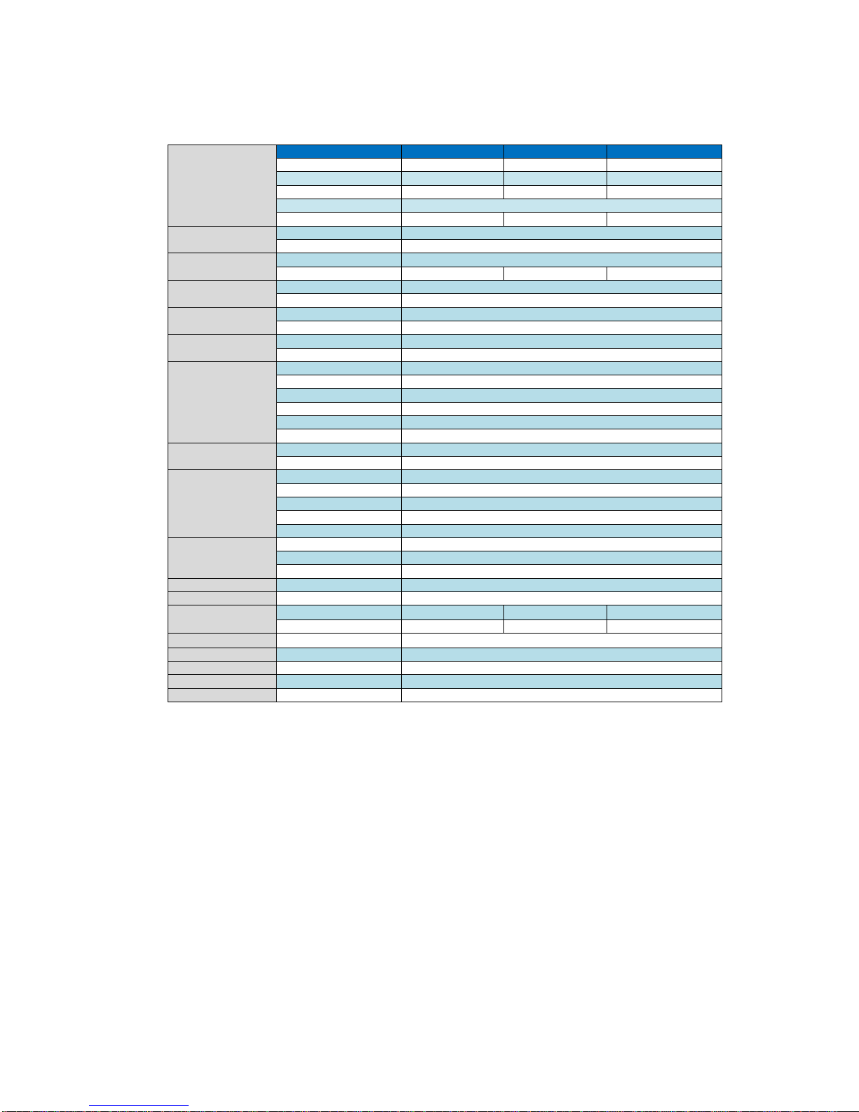
3.1.1 Specifications
Media category provides audio adjust utility for Line, Mic and volume. For some limitation,
system provides Line out and volume adjustment only but Mic in. Mic in feature could be
implemented by inquiry.
ProcessorSystem
CPU AES‐1210M *AES‐1210E *AES‐1210S
Max.Speed(Core)1.86GHz(Quad‐core) 1.46GHz(Dual‐Core)1.46GHz(Single‐Core)
L2Cache2MB 1MB 512KB
CPU/PowerCeleronN2930 E3826 E3815
BIOSAMI16MbAMIUEFIwithGUIsupport
PowerConsumption 7.5W 7W 5W
ExpansionSlotMini‐PCIe1xhalf‐size
mSATA1xMini‐PCIefull‐size
MemorySpecification(SO‐DIMM) 1xDDR3L‐1333
SystemMax.Capacity 8GB 8GB 4GB
GraphicsVGA 1xVGA(1920x1200)
HDMI1xHDMI(1920x1200)
EthernetInterfaceController RealtekRTL8111E‐VL
Connector2xRJ‐45
SATAMaxDataTransferRate SATAII(3.0Gb/s)
SATAconnector2xSATAII,SATA1&SATA2(SATA1forSATADOM,SATA2formSATA)
SystemRearI/O
VGA1xDB‐15
HDMI1xHDMI
Ethernet2 xRJ45
USBTypeA2 xUSB3.0,2xUSB2.0
Audio1xAudioports(Line‐out)
SystemPowerInput 1xDC‐Jack, 9‐36VdcInputbyDC‐Jackorby2‐pinphoenix
Option(frontbezel)OptionCOM3/4DB‐9byrequestonfrontbezel
OptionGPIO8‐bitDB‐9byrequestonfrontbezel,4xGPI+4xGPO
SystemFrontBezel
Power‐OnButton1xMomentbuttonswitchtoturn‐onsystem
SystemPowerLED 1xLEDforsystempowerstatus
HDDLED1xLEDforSATAHDDdataaccessstatus
COMPorts2xDB‐9
USB4xUSB2.0typeA
OperationSystem
WindowsXP,XP64bit N/A
Win7Win732‐bit,64‐bit
Win8.1,Win8 Win8.1/832‐bit,64bit
WatchdogTimerOutputandInterval Systemreset,programmable1~255sec/min;1sec.or1min./step
PowerRequirementDCInput9‐36Vdcinput(optionDC12V50Wadapter)
EnvironmentOperatingTemperature 0~50℃(32~140℉)0~50℃(32~140℉)0~60℃(32~140℉)
AirFlowcondition With0.7m/sairflow With0.7m/sairflow
StorageTemperature ‐40~85℃(‐40~185℉)
PhysicalSizeDimensions202mm(W)x140mm(D)x30mm(H)
PackingSizeDimensions300mm(W)x260mm(D)x125mm(H)
WeightN.W/G.W.1.0Kg/1.5Kg
CertificationsEMCCE,FCCClassB
Table of contents
Popular Industrial PC manuals by other brands


Siemens
Siemens SIMATIC IL43 operating instructions

Advantech
Advantech ITA-3650G Series Startup manual

Advantech
Advantech TPC-xx51T-x3BE Series user manual

Hitachi
Hitachi HF-W100E instruction manual

MiTWell
MiTWell KUBER-2000-IT Series user manual

Digital Equipment
Digital Equipment Pro-face PS-3450A Series Reference manual

Phoenix Contact
Phoenix Contact VALUELINE IPC datasheet

Aaeon
Aaeon PFM-550S user manual

BENECOM
BENECOM BPC-203 SERIES user guide

IBASE Technology
IBASE Technology AMS200 user manual

IEI Technology
IEI Technology uIBX-230-BT Series user manual

Moxa Technologies
Moxa Technologies MC-7400 Series Quick installation guide