3
I. Introduction
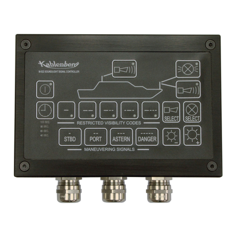
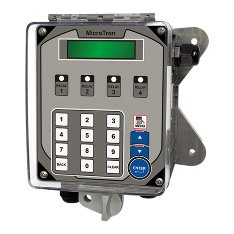
NanoTron microprocessor based controllers are designed to provide a wide range of control functions for
recirculating water treatment systems. The controller is programmed through a front panel keypad and can
be congured to provide a customized control system for your application. Your particular unit’s functions can
be determined by comparing the units model number to the Model Numbering table listed below.
Model Numbering
NanoTron units have several base system control functions and unit optional features. Your unit may be
supplied with one or more of the features described in this manual. To determine what features apply to your
unit check the model number label located on the controller enclosure. Example: NANO-P-E
Base Control Function
P- pH Control and 1 Feed Timer
R - ORP Control and 1 Feed Timer
Whole Unit Optional Features
A- Conduit Connections
A3 - Conduit with CE
E- Flow Switch Assembly with sample port
Y- ETL Listing / Approvals
W- Larger enclosure with clear lockable cover
II. Description
NanoTron units are designed to automate pH / ORP control and the addition of various chemicals or activate
other devices via a relay output.
Nano-P and Nano-R units include:
• One totalizing water meter input that can be congured for contacting head or hall eect meter inputs.
• One drum level input that can be set for one of the following: alarm display only, alarm display and force
of relay 1, alarm display and force o relay 2 or alarm display and force of relay 1 & 2.
• Two mechanical relay outputs with normally open and normally closed contacts that can be congured
for powered or dry contact relay operation (see page 4 diagram). Relay 1 is labeled “pH” or “ORP” and
Relay 2 is labeled “Relay 2” if pigtails are provided.
• A “force on” timer that allows for manual activation of the relays for a user dened amount of time.
pH Control (P) - The pH function monitors and controls pH on a scale of 0-14 pH units. The unit can be
congured for single or dual set point control. Relay 1 is controlled be the single pH set point with the following
settings: Set Point (rising for acid feed or falling for caustic feed); Dierential (the amount of reading change
that must occur before the relay is turned o); Limit Timer (the relay is forced o if the limit time is met).
For dual set point control to feed both an acid and a caustic the Relay 2 Set menu must be congured for Dual
pH instead of a timer. This setting will add additional settings in the pH Set menu for the second set point.
Relay 1 will operate o of the falling setpoint and Relay 2 o of the rising.
The High, Low Alarm settings and limit timer are the same for single or dual pH set point control.
ORP Control (R) – The ORP function monitors and controls ORP on a scale of 0 to +1000 mV using relay 1.
Relay 2 Set – The second relay can be controlled by one of the following modes: Set Point 2 for pH units,
Alarms for P (not doing dual set point) or R units or one of the selectable timers below:
1. Pulse Timer – Accepts dry contact pulses from a water meter (supplied separately). It can accumulate1-9999 pulses to activate
the timer to run from 0-99 minutes, 59 seconds. Timer will store up to 5 additional activations during an individual run time.
2. Recycle Timer – Provides a user dened “o” time in HH:MM and a user dened “on” cycle in MM:SS that is repeated
constantly.
3. 28-Day Timer – 28-day feed timers, typically used for biocide feed are based on a 28-day cycle with two independent
programmable feed cycles allowing for feed on selectable days and weeks.
4. Utility – Relay on all of the time.


