3
I. Introduction
The Advantage Controls Series 75 RO controller is designed for the small commercial Reverse
Osmosis system. This controller incorporates relay outputs and dry contact inputs to either run or
shutdown as necessary for proper operation. The S75 Controller has up to three relay outputs: inlet
solenoid valve, RO pump motor, and an optional ush solenoid valve.
II. Installation
1. The RO pump motor or motor starter and the solenoid valves must be of the same voltage 120
or 240 volt.
2. Conrm that the (3) input signals - pressure switch, tank level switch and pretreat switch are all
of the same conguration, normally open or normally closed.
3. Conrm the desired switch settings for your operation. The switches are factory set to the OFF
Position: Auto Reset (disabled), Pressure Fault Retry (disabled), Tank Full restart time delay (2
seconds), Input contact type (NC, open to operate). If you desire to change any switch functions,
move that switch to the ON Position. [See table below].
4. Wire to the controller as follows:
• Remove the enclosure cover.
• Mark and drill necessary electrical entry holes in the empty enclosure.
• Terminate necessary wiring to the Quick Connect terminals as required (See diagram on
page 4). Each terminal is labeled for the proper connection. Terminals P1-P9 are high
voltage for power, motor, inlet and ush solenoid. Utilize proper 3 conductor wire size for
the appliance.
WARNING: The controller is rated for maximum 20 amp total load. Terminal strip P11 is dry
contact for input signals from tank full, pressure fault and pretreat lockout. Use small gauge 2
conductor cable for these wire connections.
5. Position and mount the enclosure in the desired location.
6. Connect all wiring to the appropriate appliances (Do not connect to the power source at this
time).
7. Reassemble the enclosure, be sure to coil and leave some slack wire inside the enclosure.
8. Connect the power wire 120- 240 volt to its source.
9. Proceed to push the power switch ON and test the completed unit as necessary.
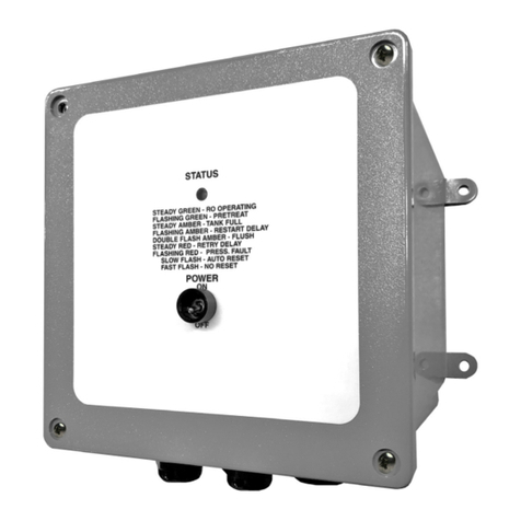
10.Notice the status LED to conrm system status.
SWITCH O Position On Position
1AUTO RESET DISABLED AUTO RESET ENABLED
2RETRIES DISABLED RETRIES ENABLED
32 SEC RESTART 15 MIN. RESTART
4N.O. SWITCHES N.C. SWITCHES
5FLUSH OFF FLUSH ON
6FLUSH TF FLUSH ET
WARNING: All switch inputs must be dry contact only. If voltage is applied to these inputs, damage
to the controller will result. For power with neutral and hot leads, L1 is hot and L2 is neutral.
!
!
