2
Installation
1. Conrmthatthecontrollerisconguredforthepropervoltage:120,240or
24-volt.SeeIDlabel,aswellasthelabellocatedontopofthetransformer
designating voltage. (See Fig. 1)
2. TheROpumpmotorormotorstarterandthesolenoidvalvesmustbeofthe
same voltage: 120, 240, or 24-volt.
3. Conrmthatthe(3)inputsignals–pressureswitch,tanklevelswitch,
andpretreatswitch–areallofthesameconguration,normallyopenOR
normallyclosed.
4. Conrmthedesiredjumpersettingsforyouroperation.Thejumpersare
factorysettoPositionBAutoReset(disabled),PressureFaultRetry
(disabled),TankFullrestarttimedelay(2seconds),Inputcontacttype(NC,
opentooperate),andushontankfull.Ifyouwishtochangeanyjumper
functions,movethatjumpertoPositionA.(SeeTableonnextpage.)
5. Ifawireharnessisprovidedwiththiscontroller,skipthissectionand
proceedtoStep6.Ifwiringtothecontrollerisrequired,proceedasfollows:
A. Remove the enclosure cover.
B. Markanddrillnecessaryelectricalentryholesintheempty
enclosure.
C. Terminatenecessarywiringtotheterminalstripsasrequired.
(SeeFig.1)Eachterminalislabeledfortheproperconnection.
TerminalstripP1ishighvoltageforpower,motor,inlet,andush
solenoid.Utilizeproper3conductorwirefortheappliance.
WARNING:Thecontrollerisratedformaximum20-amptotalload.
TerminalstripP2islow-voltageforinputsignalsfromtankfull,pressure
fault,andpretreatlockout.Usesmallgauge2conductorcableforthese
wire connections.
6. Position and mount the enclosure in the desired location.
7. Connect all wiring to the appropriate appliances. Do not connect to the
power source at this time.
8. Reassemble the enclosure, be sure to coil and leave some slack wire inside
the enclosure.
9. Turn the power switch to the OFF position.
10. Connect the power wire 120, 240, or 24-volt to its source.
11. Proceed to turn the power switch On and test the completed unit as
necessary.
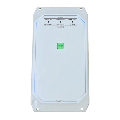
12.ObservethestatusLEDcolortoconrmsystemstatus.
!
