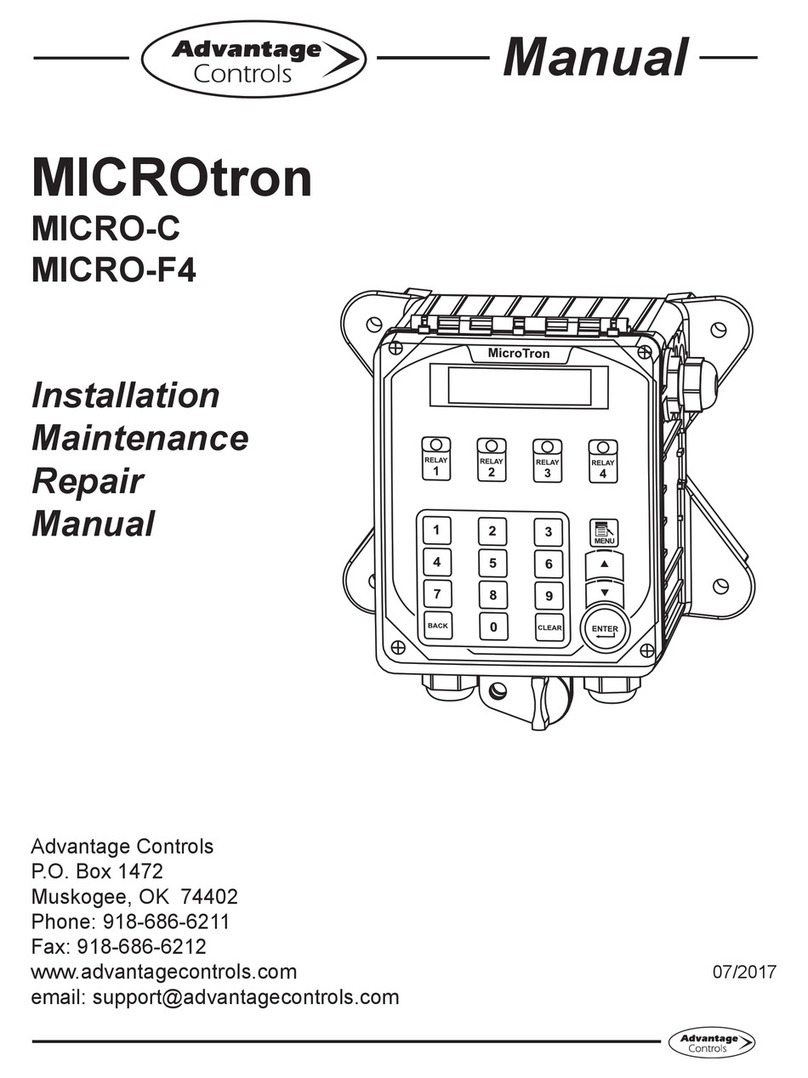
Advantage Controls MicroTron User manual

1
Manual
MicroTron
Tower Controller
Installation
Maintenance
Repair
Manual
Advantage Controls
4700 Harold Abitz Dr.
Muskogee, OK 74403
Phone: 918-686-6211
Fax: 888-686-6211
www.advantagecontrols.com
email: [email protected]
04/19

2
MicroTron Tower Controller
Instruction & Maintenance Manual
Table of Contents
Contents Page
I. Introduction................................................................................. 3
Model Numbering ....................................................................... 3
II. Description of Unit ...................................................................... 4
III. Installation .................................................................................. 5
Electrical Wiring.......................................................................... 5
Mounting Instructions ................................................................. 5
Conduit Layout for LCD Display ................................................. 6
Typical Installation ...................................................................... 6
Electrode Installation .................................................................. 7
IV. Front Panel Description.............................................................. 8
V. System Operation Overview....................................................... 9
A. Description of Set Up Menu Screens.................................... 9
1. Calibration...................................................................... 10
2. Bleed Set........................................................................ 11
3. pH Feed Set................................................................... 12
4. ORP Feed Set................................................................ 13
5. Chem Feed Set.............................................................. 14
6. Biocide Set..................................................................... 15
7. Clock Set........................................................................ 16
8. System Menu Set........................................................... 17
9. Diagnostics Menu........................................................... 19
B. Run Menu............................................................................ 20
VI. Maintenance............................................................................. 21
VII. Troubleshooting........................................................................ 21
VIII. Warranty & 30 Day Billing Memo Policy ................................... 23
Instructions herein apply to all MicroTron tower controllers.
Additional options described in this manual may or may
not be present on your unit. Refer to Model Numbering on Page 3.

3
I. Introduction
MicroTron controllers are microprocessor based menu driven units for control of recirculating and other
water applications. All settings are entered into the controller through a simple front panel keypad which
includes relay test keys.
Model Numbering
MicroTron controllers have several base functions and optional features available. Your unit may be supplied
with one or more of the options that are described in this manual. To determine what features apply to your
unit, check the model number label located on the controller enclosure.
Base Functions
All model numbers can be broken down as follows
and will start with an Mor L.
MMicroTron with a VFD display
LMicroTron with an LCD display
CConductivity Control
C-0 Conductivity Monitor only
C-2 Adds make-up conductivity function
FSingle programmable feed timer
F-2 Dual feed timers
F-3 Triple feed timers
F-4 Quadruple feed timers
F-5 Five feed timers
BSingle 28 day timer
B-2 Dual 28 day timers
B-3 Triple 28 day timers
B-4 Quadruple 28 day timers
PpH control
P-0 pH monitor only
P-2 pH control with dual set points
RORP control
Optional Features
This list represents our most popular options.
AConduit connections
A-6 On/Opowerswitch
A-7 Lower enclosure
C-1 0-5V non-isolated output
C-4 Single 4-20mA non-isolated output
C-6 Single isolated 4-20mA output
D220 V service (conduit only)
E Mountedowswitchassembly
MAlarm relay options
M-1S Sonic alarm buzzer with silence switch
NNon standard conductivity scales
QAlternate electrodes
RMolex connector on conductivity electrode
V Digitalinputforbleed-owatermeter
WPower relay 1.5 HP max, 25 amps
XTank low level alarms
Y Bleedowalarm(requiresowswitch)
Z-6 One water meter input for each chemical
feed timer
Z-11 Lockout chem feed with low conductivity alarm
9 Paddlewheelowmeterinput
Note:Thelistoffunctionsandoptionsrepresentspastandcurrentoerings.
Some of these may no longer be available on new units, but are listed for reference.

4
II. Description
Control Functions
Each of the control functions is based on an analog input from a probe and will include user settable relay
control settings along with a High and Low Alarm setting and Limit Timer. Each control function will include
a control relay output. When the reading reaches the Set Point the control relay is activated until the
readingchangesbytheDierentialamount.
1. Conductivity - The conductivity function of the controller is designed to monitor and control
Total Dissolved Solids (TDS) in a recirculating system like a cooling tower in terms of electrical
conductivity measured in MicroSiemens/cm. This control function is also referred to as bleed. Units
with conductivity and the make-up conductivity function can control the TDS of the tower system
toacyclesofconcentrationbycalculatingthedierencebetweentheincomingmake-upwater’s
conductivityandthesystem’sconductivity
2. pH - The pH function monitors and controls pH on a scale of 0-14 pH units.
3. ORP - The ORP function monitors and controls ORP on a scale of +/- 999 mV.
Chemical Feed Timers
Selectable Chemical feed timers (base function F) are designed to automate the addition of various
chemicals by activating a relay output. Multiple timers can be supplied depending upon the model number
and each timer will include a relay output. All timers can be programmed to be one of the following types.
1. Pulse Time - This timer accepts dry contact pulses from a make-up water meter (supplied
separately). It can accumulate 1-99 pulses to activate the timer to run from 0-99 minutes in minutes
and seconds.
2. Feed with Bleed - This timer activates the relay output simultaneously with the bleed. The timer
can limit the amount of time the relay output will be on during the bleed cycle, thereby preventing
chemical overfeed.
3. Feed after Bleed-Thistimeractivatestherelayoutputbasedonauserdenedpercentageof
thebleedotime.Therelayisactivatedafterableedcycleandrunsforthesetpercentageofthat
bleed cycle. A limit time can also be set for the maximum amount of time the timer can run for one
cycle.
4. Percentage - The relay is on for a percentage of a continuously repeating cycle time. The percentage
timer can be set from 1 to 99% and the cycle time can be set from 1 second to 99 minutes and 59
seconds.
28-Day Feed Timers
28-day feed timers, typically used for biocide feed are based on a 28 day cycle with two independent
programmable feed cycles allowing for feed on selectable days and weeks. The biocide timers also
include prebleed and bleed lockout settings. Multiple timers can be supplied depending upon the model
number and each timer will include a relay output.

5
III. Installation
Electrical Wiring
The standard MicroTron Tower controller has an internal regulated power supply that will operate in the range
of approximately 100 to 240 VAC on the incoming wiring. Output relay(s) are protected with a replaceable
fuse.Eachrelay’soutputvoltagewillequalincominglinevoltage.
Prewired units are supplied with a 16 AWG cable with 3-wire grounded USA 115 volt plug for incoming power
and 18 AWG 3-wire grounded U.S.A. 120 volt receptacle cords for all control relay outputs.
Conduit units are supplied with connectors located in the lower section of the controller. Remove the screws
of the lower panel for access and to view wiring diagram.
NOTE: Liquid tight ttings and labeled signal lead cables are provided for all signal (low voltage)
connections, such as water meter, low drum level, ow switch and 4-20mA outputs, for both pre-wired
and conduit units.
Mounting Instructions
Select a mounting location that provides the operator easy access to the unit and a clear view of the controls
through the cover of the controller. The location should be convenient to grounded electrical connections, the
requiredsamplelineplumbing,andinstalledonastableverticalsurface.
CAUTION
1. There are live circuits inside the controller even when the power switch on the front panel is in
the OFF position. Never open the front panel without rst disconnecting power from the outlet.
Prewired controllers are supplied with an 8 foot, 18 AWG power cord with USA style plug. A #1
Phillips driver is required to open the front panel.
2. Low voltage signal wires (probes, ow switch, water meter, etc.) should never be run
in conduit with high voltage (like 115VAC) wires.
3. Never attempt to land connections to the controller without rst disconnecting power from the outlet.
4. Do not block access to disconnect power during mounting and installation.
5. The controller should be connected to its own isolated circuit breaker, and for best
results, the ground should be a true earth ground, not shared. Any attempt to bypass the grounding
will compromise the safety of users and property.
6. The electrical installation of the controller must be performed by trained personnel only and
conform to all applicable National, State and Local codes.
7. Operation of this product in a manner not specied by Advantage Controls may result in damage
to equipment or persons.
8. Avoid mounting in locations that expose the controller to direct sunlight, vapors, vibration,
liquid spills or extreme temperatures; less than 0°F (-17.8°C) or greater than 120°F (50°C).
EMI(electromagnetic interference) from radio transmissions and electric motors can also cause
damage or interference and should be avoided.
! !

6
Conduit Layout for LCD Display
Logic Board
Serial Line
Connection
R
B
R
B
R
B
R
B
Level Wand
Level 2
Level 3
Level 4
Water
Meter
Input
Make/up
Switch
Make/up
Cal.
Make/up
Cond.
Probe
B
R
B
R
Pressure
Sensor #1
Pressure
Sensor #2
R
B
ISO
4-20
Out
To 4-20
Board
LCD
Contrast
TP-8
TP-6
TP-7
TP-10
-12
+5
+5
Gnd
Gnd
+12
TP-3
GND
TP-4
TP-2
TP-5
TP-1
-5 +5
-12 +12
R
B
R
B
R
B
R
B
R
B
Pulse 1
Pulse 2
Pulse 3
Pulse 4
Bleed Meter
Flow
R +12 VDC
B GND
B
R
W
G
B
R
W
G
Eprom
ADJ.
TP6
Cond. Switch
OFF / ON
Cond.
Cal.
Conductivity
Probe
OFF
ORP
Test
OFF
ORP
Test
10 9
21
Ribbon
Cable for
Relays
SIGNAL
GROUND
+ vdc for opt.9
Relay / Power Board (Rev. D)
Ribbon Cable
2
1
10
9
POWER INPUT
POWER SUPPLY
Relay 1 Relay 2 Relay 3 Relay 4 Relay 5
5A (R1)
5A (R3)
5A (R2) 5A (R4)
5A (R5)
NEU GND
N.O. N.C.
NEU GND
N.O. N.C.
NEU GND
N.O. N.C.
NEU GND
N.O. N.C. NEU GND
N.O. N.C.
H N G
Rev. D
Relay / Power Board (Rev. B)
Ribbon Cable
2
1
10
9
5A
POWER INPUT
H N G
Relay 5
5A
5A
Relay 3
5A
Relay 2
NET
GND
N.O.
N.C.
5A
Relay 1 Relay 4
POWER SUPPLY
NET
GND
N.O.
N.C.
NET
GND
N.O.
N.C.
NET
GND
N.O.
N.C.
NET
GND
N.O.
N.C.
Rev B
Relay / Power Board (Rev. C)
Relay 5
Relay 3Relay 2Relay 1 Relay 4
POWER SUPPLY
Relay / Power Card (REV D)
Green (-12)
White (+5)
Red (+12)
Black (Gnd)
FUSE
FUSE
FUSE
FUSE
FUSE
1
Relay 1
2
Relay 2
4
Relay 4
35
N.O N.C NET GRD
N.O N.C NET GRD
N.O N.C NET GRD N.O N.C NET GRD
N.O N.C NET GRD
H N G
POWER INPUT
Ribbon Cable
1
2
9
10
Typical Installation
BLOWDOWN
COOLING TOWER
CIRCULATION PUMP CHILLER
MAKE-UP
WATER METER
BLEED VALVE

7
Electrode Installation
MicroTrontowercontrollersmaycomeconguredforvariousrecirculatingwatersystems.Listedbelow
areinstructionsfortypicalcoolingtowerinstallations.Yourspecicinstallationrequirementsmaydierbut
should conform to these instructions as much as possible for proper operation.
Thestandardprobe(s)and/orowassemblyforcoolingtowerinstallationsisconstructedofschedule
80PVCandsuppliedwith¾”slipttingsforinstallingintoasampleline.Toinsureproperoperationthe
samplelinemusthaveaowrateof3-10gpm.Inletpressuremustbehigherthanoutletpressureinorder
forwatertoowpasttheelectrode(s)attherequiredrate.Theprobesaretemperaturecompensatedfor
increased accuracy.
NOTES:
1. Install an isolation valve on either side of the ow assembly so electrodes can be
easily isolated for removal and cleaning.
2. A line strainer is recommended upstream from the probes to protect against fouling
and damage.
3. Mount pH electrodes vertically.
4. Units with a ow switch require the needed ow rate to operate the relay outputs.
5. Tap points for sample line should not be at the top or bottom of the supply piping to
reduce air or debris introduction to sample line.
WARNINGS:
1. Electrodes are O-ring sealed, which if damaged will cause a leak.
2. Do not allow pH sensor tips to dry out, damage will occur.
3. Do not exceed a water temperature range of 32°F to 140°F.
4. Do not exceed a maximum pressure of 150 psi.
FS-OC FS-F2
E-30
FS-FC
FS-SP
-or-
PE-21
OE-21
PE-NUT
pH Probe
ORP Probe
FS-SPRING
If ordered
OR
FS-T
TFS-OC
TFS-C
Conductivity
Probe
FS-B1-SP
MW-T-3
MW-T-3-2
MW-T-3-3
E-30
E-4A
SampleValve
E-30-PH E-30-PH
UNION-3/4T
2C0A-150

8
IV. Front Panel Description
READ: 1x16 (1/4”) Alpha Numeric Display.
CONTROL: Relay 1, Relay 2, Relay 3, Relay 4 - HOA switches for control relays.
SET UP/RUN key - System initializes into RUN mode. Press this switch to toggle the controller
from SET UP mode to RUN mode.
UP/DOWN arrows - Used to change the display from one line to the next. All menus are circular,
so when all items in a menu have been displayed, the display will return to the
originally displayed item.
ENTER key - Used to access a menu and to log a changed value into the program.
CLEAR key - Used to clear numerical values from items being changed in the SET UP
mode.
DECIMAL key - Used at certain places to change a function or displayed items. For example,
when temperature is being displayed, pressing the DECIMAL key will change
the reading from Fahrenheit to Celsius or visa versa.
NUMERICAL keys - Used to enter new values in the SET UP mode.
Standard Tower Probes
Conductivity...................................................................................................................................E-4A
pH..................................................................................................................................................PE-2
ORP.............................................................................................................................................. OE-2
ENTER
CLEAR
•
1
SET UP
RUN

9
V. System Operation Overview
MicroTron controllers have two modes of operation, RUN and SET UP. Both the RUN and SET UP menus
are circular. Pressing the DOWN key in either menu will display the next line of information on the display.
After the last item in a menu has been displayed, pressing the DOWN key will return the display to the top
line of that menu.
RUN MODE - This mode is for normal operation. The control relays will only be automatically activated
in this mode. In the RUN mode the display will read system values. If an alarm is present
thedisplayasheswiththealarmstatus.
The RUN menu will display values such as conductivity, pH, day, time, date and other
values depending upon the features present on the unit. The unit will automatically return
to the RUN mode if no keys are pressed for three minutes.
SET UP MODE - This mode is used to make adjustments to settings and readings on the controller. To
access the SET UP mode from the RUN screen, press the SETUP/RUN key. Use the
up or down arrow to scroll through the various SET UP menus. When you want to enter
aspecicSETUPmenu,presstheENTERkey.OnceyouhaveenteredaSETUPsub
menuyouwillbeabletostepthroughthatmenu’soptionswiththedownarrowkey.
Relays may be forced on while in the SET UP mode. Press the desired relay test key to
forceiton.Pressitasecondtimetoturnito.OncetheunitreturnstotheRUNmode,
relays will activate automatically.
Therelay4testkeywillactivaterelay4ontherstpress,thenwillactivaterelay5on
thesecondandwillturnboth4and5oonthethird.
A. Description of SET UP Menu Screens
The SET UP menu is the main menu circle of set up sub-menus used to customize your unit to the particular
parameters needed for your installation. Listed on the following pages is a description and menu map of each
SET UP menu.
NOTES:
1. Your unit may not have all of the SET UP menus listed depending upon your model number.
2. After you press ENTER or CLEAR to change a numerical value in the SET UP menu, use the
numberkeystodenethenewvalue.PressENTERagaintoenterthenewvalue.
3. When entering new numeric values, all available digits (characters) must be entered. The number
of available digits depends upon the scale of operation. Position of cursor indicates number of
digits to be entered.
For example, when entering a run time value for a timer in the minute and seconds scale (10:30
wouldequal10minutesandthirtyseconds).Youwouldneedtokeyinanumberof0030tomake
it 0 (zero) minutes and 30 seconds.

10
1. CALIBRATION
All MicroTron controllers are factory calibrated for
temperature, conductivity, pH and/or ORP (if present).
These values should be veried for accuracy, and
adjusted as per the instructions listed below and to the
side.
Calibrating the temperature reading, press SET UP/
RUN button. The “CALIBRATION” screen will appear.
Press ENTER and the screen will read “CALIBRATE
F”. Press ENTER to log in the new reading. To display
the reading in degrees Celsius, press the decimal key.
High Temp Alarm Set - If this is exceeded the Alarm
will activate, set to 0 to disable.
Calibrating the Conductivity with the probe in a
known solution, select “CALIBRATE uS” from the
“CALIBRATION” menu. Press CLEAR, then key in the
corrected conductivity value. Press ENTER to log in
that reading.
Calibrating the pH with the probe in solution on line.
Select “CALIBRATE PH” from the “CALIBRATION”
menu. Press CLEAR, then key in the corrected pH
value. Press ENTER to log in that reading.
Calibrating the ORP with the probe in solution on line.
Select “CALIBRATE ORP” from the “CALIBRATION”
menu. Press CLEAR, then key in the corrected ORP
value. Press ENTER to log in that reading.
The limits on this factor are from 50% to 200% and any
entry which would lead to a factor outside this range
will cause it to default back to the previous value.
NOTES:
1. After entering a new numerical value hit the
ENTER key to accept value and advance.
2. For severe calibration problems, see Reset
Zero and Recentering pH on page 22 & 23.
2. BLEED SET
-- CALIBRATION --
CALIBRATE xxxoF
To change temperature
To accept value keyed in
using number keys
HIGH TEMP xxxoF
To change value
To accept value keyed in
using number keys
CALIBRATE XXXXXuS
To change conductivity reading
To accept value keyed in
using number keys.
CALIBRATE XX.X.pH
To change pH reading
To accept value keyed in
using number keys.
CALIBRATE XXX ORP
To change ORP reading
To accept value keyed in
using number keys.
Returns to CALIBRATION screen
ENTER
CLEAR
ENTER
ENTER
CLEAR
ENTER
CLEAR
ENTER
CLEAR
ENTER
CLEAR

11
This menu is used to set bleed control parameters
including set point, dierential, high and low alarms
plus a feed limit timer.
BleedTrip - A reading above this value will activate the
blowdown relay until the reading falls by the amount of
thedierentialbelowthetrippoint.
Dierential - With a rising trip point the bleed relay
comes on if conductivity exceeds the trip point and
goes o when it falls below the trip point minus the
dierentialvalue.
The dierential may be made negative by using the
DECIMAL key during edit. If negative, the Trip Point
changes from rising to falling.
High Alarm Setting - Setting for a high conductivity
alarm condition.
Low Alarm Setting - Setting for a low conductivity
alarm condition.
Bleed Limit Timer - The bleed limit timer is set in
hours and minutes. If the unit bleeds longer than the
limit timer is set for an alarm is given. Maximum value
is 9 hours and 59 minutes. A setting of zero disables
the timer.
3. PH FEED SET
-- CALIBRATION --
BLEED TRIP XXXX
To change bleed trip point
To accept value keyed in
using number keys
DIFFERENTIAL XXXX
Tochangedierential
To accept value keyed in
using number keys
HIGH ALARM XXXX
To change high alarm setting
To accept value keyed in
using number keys.
LOW ALARM XXXX
To change high alarm setting
To accept value keyed in
using number keys.
BLEED LIMIT H.MM
To change bleed limit time
To accept value keyed in
using number keys.
Returns to BLEED SET screen
ENTER
CLEAR
ENTER
ENTER
CLEAR
ENTER
CLEAR
ENTER
CLEAR
ENTER
CLEAR

12
This menu is used to set pH control parameters
including set point, dierential, high and low alarms
plus a feed limit timer. (This menu choice will be
present only if you have the pH control option, see
model numbering on page 3.)
pH Trip - The pH reading value that will activate the
pH relay.
pH Di - Normally a rising trip point, the pH relay
comes on if pH exceeds the trip point and goes o
whenitfallsbelowthetrippointminusthedierential.
The dierential may be made negative by pressing
theDECIMALkeywhenchangingdierentialsetting.
When the dierential is negative, the Trip Point
changes from rising to falling.
High Alarm Setting - Setting for a high pH alarm
condition.
Low Alarm Setting - Setting for a low pH alarm
condition.
pH Limit Timer - The pH limit timer is set in hours and
minutes. If the unit calls for feed longer than the limit
timer is set for, an alarm is given and the pH feed is
stopped. Maximum value is 9 hours and 59 minutes. A
setting of zero disables the timer.
After entering a new numerical value hit the ENTER
key to accept value and advance.
NOTES:
If a unit has dual pH trip points, there will be
a group of settings for “PH A” followed by the
settings for “PH B”.
4. ORP FEED SET
-- PH FEED SET --
PH TRIP XXX
To change pH trip point
To accept value keyed in
using number keys
PH DIFF XXX
TochangepHdierential
To accept value keyed in
using number keys
HIGH ALARM XX
To change high alarm setting
To accept value keyed in
using number keys.
LOW ALARM XX
To change low alarm setting
To accept value keyed in
using number keys.
FEED LIMIT H.MM
To change feed limit timer setting
To accept value keyed in
using number keys.
Returns to PH FEED SET screen
ENTER
CLEAR
ENTER
ENTER
CLEAR
ENTER
CLEAR
ENTER
CLEAR
ENTER
CLEAR

13
This menu is used to set ORP control parameters
including set point, dierential, high and low alarms
plus a feed limit timer. (This menu choice will be
present only if you have the ORP control option, see
model numbering on page 3.)
ORP Trip - The ORP reading value that will activate
the ORP relay
ORP Di - Normally a falling trip point, the ORP relay
comesonifORPfallsbelowthetrippointandgoeso
whenitrisesabovethetrippointplusthedierential.
The dierential may be made positive by pressing
theDECIMALkeywhenchangingdierentialsetting.
Whenthedierentialispositive,theTripPointchanges
from falling to rising.
High Alarm Setting - Setting for a high ORP alarm
condition.
Low Alarm Setting - Setting for a low ORP alarm
condition.
ORP Limit Timer - The ORP limit timer is set in hours
and minutes. If the unit calls for feed longer than the
limit timer is set for, an alarm is given and the ORP
feed is stopped. Maximum value is 9 hours and 59
minutes. A setting of zero disables the timer.
After entering a new numerical value hit the ENTER
key to accept value and advance.
5. CHEM FEED SET
-- ORP FEED SET --
ORP TRIP XXX
To change trip point
To accept value keyed in
using number keys
ORP DIFF XXX
Tochangedierential
To accept value keyed in
using number keys
HIGH ALARM XX
To change high alarm setting
To accept value keyed in
using number keys.
LOW ALARM XX
To change low alarm setting
To accept value keyed in
using number keys.
FEED LIMIT H.MM
To set feed limit time
To accept value keyed in
using number keys.
Returns to ORP FEED SET screen
ENTER
CLEAR
ENTER
ENTER
CLEAR
ENTER
CLEAR
ENTER
CLEAR
ENTER
CLEAR

14
Units with selectable feed timer(s) will have this SET
UP menu for selecting the chemical feed method
and setting the feed time. A selectable feed timer
can be programmed to be one of the following:
1. PULSE TIME - A timer activated by dry
contacts from a contacting head water meter
and includes an accumulator for counting the
number of pulse (contacts) before starting the
timer.
2. WITH BLEED - A feed limit timer that runs
during a bleed cycle. The chemical feed will run
for as long as the bleed occurs or until the limit
time is reached.
3. POST BLEED - This timer counts how long
a bleed cycle lasts then runs the chemical
feedafterthecycleisoverforauserdened
percentage of the bleed time. A limit timer
prevents over feeding.
4. PERCENTAGE - A continuously repeating
timer where the cycle timer can be programmed
along with the percentage of ON time for the
cycle.
6. BIOCIDE SET
-- CHEM FEED SET --
Shows timer currently selected
Tochangetoadierenttimer
To cycle through timer options
CHEM A PULSE TIME
CHEM A WITH BLEED
CHEM A POST BLEED
CHEM A PERCENTAGE
To Select timer
To bypass the feed method selection
-- CHEM A POST BLEED --
CHEM A PERCENT XX
To change percentage
CHEM A TIMER XX Min.
To change limit time
Returns to CHEM FEED SET
-- CHEM A PERCENTAGE --
CHEM PERCENT XX
To change percentage
CHEM A CYCLE XX.XX
To change cycle time
Returns to CHEM FEED SET
ENTER
ENTER
ENTER
-- CHEM A PULSE TIME --
CHEM PULSES XX
To change # of pulses
CHEM A TIMER XX.XX Min.Sec
To change Chem A timer
Returns to CHEM FEED SET
-- CHEM A WITH BLEED --
CHEM A LIMIT XX.XX Min.Sec
To change limit
Returns to CHEM FEED SET
ENTER
ENTER
ENTER
ENTER
ENTER
ENTER
ENTER

15
Units with a biocide timer will have this SET UP menu
for setting biocide feed times. Biocide Set Menu
consists of two weekdays, week and start times, one
feed length time and an overall prebleed and lockout
setting for each biocide.
BIO __ (A1,A2,B1,B2...) WEEKDAY - Select from
Sunday through Saturday, or TuesThrSat, MonWedFri,
Every Other day, Every Day or No Day. A setting of No
Day disables timer.
BIO__(A1,A2,B1,B2 ...) WEEK - Select week (1-4),
Even Weeks, Odd Weeks, or Every Week. A setting of
No Week disables timer.
BIO__(A1,A2,B1,B2 ...) MONTH - Select month
(1-12), Even Month, Odd Month, or Every Month.
A setting of No Month disables timer.
BIO_(A,B,C...)TIME HH.MM - Start time based on 24
hour clock, in hours and minutes.
BIO_(A,B,C...) LENGTH H.MM - Feed time in hours
and minutes can be set up to 9 hours and 59 minutes,
0 (zero) disables both start times for that biocide.
BIO_ (A,B,C...) PREBLEED H.MM - Prebleed and
lockout settings are in hours and minutes, with a
maximum of 9 hours and 59 minutes, 0 (zero) disables
timer. When the clock reaches a start time for any of
the four timers, the Prebleed is begun.
BIO_(A,B,C...) LOCKOUT H.MM - The lockout timer
is a timer that starts after the biocide feed time is
nished.Thetimercanbesetforatimeupto9hours
and 59 minutes to lock out the bleed.
7. CLOCK SET
-- BIOCIDE SET --
Shows BIO A timer 1 activation day
To change day of the week
To cycle through day options
SUN,MON,TUES,WED,THUR,FRI,SAT,
ALTERNATE ...
To select day
Shows BIO A timer 1 activation week
To change week
To cycle through week options
press ENTER to set week
Shows BIO A timer 1 activation month
To change month
To cycle through month options
press ENTER to set month
Shows BIO A Timer 1 start time of day
To change Time of Day
To enter time keyed in using
number keys
Menu repeats for BIO A Timer 2
BIO A LENGTH 0.00 (H.MM)
To change length
To accept value keyed in
using number keys.
BIO A PREBLEED 0.00 (H.MM)
To change length
To enter time keyed in
using number keys.
Continued..
ENTER
ENTER
ENTER
ENTER
ENTER
ENTER
CLEAR
ENTER
CLEAR
ENTER
CLEAR
BIO A LOCKOUT 0.00 (H.MM)
To change length
To enter time keyed in
using number keys.
Program repeats for addional biocide
timers if ordered (B, C, and D)
ENTER
CLEAR

16
The CLOCK SET menu is for adjusting the time, date
and day of the week.
After entering a new value, hit the ENTER key to
accept the value and advance.
The clock time is based on a 24 hour clock. So, a time
of 1 pm would be shown as 13.00.00.
NOTES:
If unit doesn’t have a biocide timer, there
will not be a SET WEEK selection.
8. SYSTEM SET MENU
-- CLOCK SET --
SET TIME XX.XX.XX (hh.mm.ss)
To change clock setting
To accept value keyed in
using number keys
SET DATE XX.XX.XX
To change date
To accept value keyed in
using number keys
SET WEEK X
To change week
To cycle through week options.
To set week
Returns to CLOCK SET
ENTER
CLEAR
ENTER
ENTER
CLEAR
ENTER
ENTER

17
Thismenuisusedtocongurethecontrollertospecic
operational needs. All of the items in this menu may
not apply depending on the controller model but will
always be present.
NOTE: Do not use this menu to make calibration
adjustments. Use the Calibration screen.
PASSWORD - If a value of 0000 is entered, a
passwordisnotrequired.Ifapasswordis
entered, it must be used to operate the controller.
Iftherstdigitiszero,relaysmaybeactivated
without a password.
RESET WATER METER COUNT - Does not
apply unless the unit has selectable feed timer.
DRY CONTACT HEAD - Select a contacting head
watermeterorahalleectpaddlewheelmeter.
Anytime this setting is changed the GAL/PULSE
value will need to be re-entered.
GAL/PULSE - If a feed timer is using a contacting
head water meter this tracks make-up volume by
enteringthenumberofgallonsacontactequals.
Use•keytochangetopulse/galforowmeter.
STRAIGHT/PROPORTIONAL OUTPUTS - A
straight output setting means the optional 4-20
output span will be the same as the full scale.
The proportional setting allows the span of the
4-20 mA output to be selected by the user based
onthesetpointanddierential.
LOW DRUM NO PUMP/PUMP LOW DRUMS - If
unit has low level alarms, allows the associated
feedtimertobeforcedowhendrumislow.
COMM Setup:
BAUD RATE - For units ordered with the serial
line or modem option.
ALARM CALL - For units with modem.
FLOW WHEN CLOSED -Forowswitches.
-- SYSTEM SET --
PASSWORD XXXX
Numeric keys to set
password
RESET METER
Count zeroed
DRY CONTACT HEAD
To change to HALL EFFECT
ENGLISH UNITS
METRIC UNITS
GAL/PULSE
Numeric keys to change
gal/pulse
BLEED/PULSE
Numeric keys to change
gal/pulse for bleed
STRAIGHT OUTPUTS
To change to PROPORTIONAL
OUT
PUMP LOW DRUMS
To change LOW DRUM/ NO
PUMP
BAUD RATE 1200
To change baud rate
System Set continued on next page.
ENTER
ENTER
ENTER
ENTER
ENTER
ENTER
ENTER
ENTER
ENTER

18
SYSTEM SET (continued)
FLOW ALARM - With FLOW ALARM ON when
thesystemlosesow,analarmsignalcanbesent.
FLOW ALARM OFF means that no alarm signal is
sentintheeventoflossofsystemow.
CONCURRENT - Only applies if there are two or
more feed timers. This allows all feed timers to
become active simultaneously together.
SEQUENTIAL - Allows the feed timer to become
active in a chronological order based on settings.
ZERO CONDUCTIVITY - This is normally not
required, and is not recommended to use this
function unless instructed to do so by the factory.
NO BIOS WITHOUT FLOW - Allows the biocide
timer(s)torunonlywithaowconditionortoignore
theowandalwaysrunevenwithoutow.
FEED OK WHEN BIO - The chemical feed timer
can be prevented from activating during a biocide
timer run time.
NO BLEED ALARM-Withtheoptionalbleedow
alarm, the unit can produce an alarm if it is not
sensingowinthebleedlinewhenbleeding.
FEED OK IF BLEED - Lets the unit feed chemical
only when not bleeding or at anytime it is bleeding
if called for.
9. DIAGNOSTICS MENU
FLOW WHEN CLOSED
Flow When Open
FLOW ALARM ON
FlowAlarmO
FEED SEQUENTIAL
Feeds Concurrent
ZERO CONDUCTIVITY
Back to CALIBRATION
NO BIOS W/O FLOW
Bios With Flow
FEED OK WHEN BIO
No Feed When Bio
NO BLEED ALARM
Bleed Alarm
FEED OK IF BLEED
NO FEED IF BLEED
Return to SYSTEM SET
ENTER
ENTER
ENTER
ENTER
ENTER
ENTER
ENTER
ENTER

19
This menu is used to select, enter and test the
following items.
MODEL NUMBER - Read only screen.
SOFTWARE VERSION NUMBER - Read only
screen. Please have this number should you need to
contact customer service.
Have both available for service
TEST DISPLAY - Press ENTER and all pixels will
ash.Makeavisualchecktoseethatallpixelsare
lit.
TEST KEYPAD - Press ENTER, then press each
individual key to test its function. NOTE: Pressing the
SET UP/RUN key returns display to the main menu.
Pressing ENTER again returns to TEST KEYPAD.
RESET CALIBRATE - Resets ALL calibration data
to factory default calibration.
LEVELS INACTIVE - Press ENTER to select
between having level alarms active or inactive.
TEMP A/D - Shows the raw analog to digital value
for the temperature reading.
COND A/D - Shows the raw analog to digital value
for the conductivity reading.
CAL FACTOR - Shows internal calibration varible.
(slope of conductivity line) Default = 1000
ZERO FACTOR - Similar to calibration factor.
(zero point of conductivity line) Default = 0
These 4 screens aid in troubleshooting, please
havethisinformationavailableifyourequireservice
concerning conductivity readings.
B. Run Menu
-- SYSTEM SET --
MODEL # LCFB-2
FIRMWARE V.(n)
TEST DISPLAY
Displaywillash(allspaces
should light) press ENTER
againtonishtest
TEST KEY PAD
Key on keypad pressed,
corresponding number appears
ondisplay,ENTERtoquit
RESET CALIBRATE
If pressed resets calibrations to
factory defaults
LEVELS INACTIVE
Press ENTER to change
to ACTIVE
TEMP A / D
CONDUCTIVITY A / D
CAL FACTOR
ZERO FACTOR
Returns to DIAGNOSTICS
ENTER
ENTER
ENTER
ENTER

20
During normal operations the controller will be in the RUN mode where current values are displayed. If left in
the SET UP mode the display will revert to the RUN mode screen if no keys are touched for 3 minutes. If an
alarmispresentitwillbeashedonthescreenintheRUNmode.
While in the RUN mode if you hit the down arrow the following items may be shown:
COND Current conductivity value.
PH Current pH value.
ORP Current ORP value.
TEMP Current water temperature.
DAY-TIME Current day of the week and time.
DATE Current date.
BLEED TIME Ifbleeding,howlongithasbeenbleedingo.
CHEM (A) If a chemical feed relay is on, how long it has been on.
GALLONS If a water meter is being use, total number of gallons made up.
WATER METER If a water meter is being used, number of contacts
BLEED METER Ifableed-owatermeterisbeingused,totalnumberofgallon.Ifbleed/pulse=0
bleed pulses is displayed otherwise bleed gallons
VI. Maintenance
Table of contents
Other Advantage Controls Controllers manuals
Advantage Controls
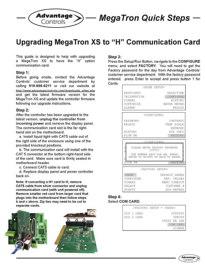
Advantage Controls MegatronXS User manual
Advantage Controls
Advantage Controls 75 Series User manual
Advantage Controls
Advantage Controls MegaTron Operating instructions
Advantage Controls
Advantage Controls MegatronXS Operating instructions

Advantage Controls
Advantage Controls MegaTronMT User manual
Advantage Controls
Advantage Controls 200 Series User manual
Advantage Controls
Advantage Controls MegaTron Series User manual

Advantage Controls
Advantage Controls MegatronXS Quick start guide
Advantage Controls
Advantage Controls MINI-TROL IF User manual

Advantage Controls
Advantage Controls MegaTron User manual
