SmartSwarm 243 User Manual x
List of Figures
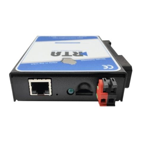
Figure 1.1 Front View..................................................................................................................... 3
Figure 1.2 Rear View...................................................................................................................... 3
Figure 1.3 Top View ....................................................................................................................... 3
Figure 1.4 System LED Panel........................................................................................................ 4
Figure 2.1 Installing the Antenna.................................................................................................... 8
Figure 2.2 Positioning the Antenna ................................................................................................ 8
Figure 2.3 Wall Mount Installation.................................................................................................. 9
Figure 2.4 Wall Mount Installation................................................................................................ 10
Figure 2.5 Installing the DIN-Rail Mounting Kit............................................................................. 10
Figure 2.6 Correctly Installed DIN Rail Kit.................................................................................... 11
Figure 2.7 Removing the DIN-Rail................................................................................................ 11
Figure 2.8 Ethernet Plug & Connector Pin Position...................................................................... 12
Figure 2.9 Installing the Power Cable........................................................................................... 12
Figure 3.1 Login Screen............................................................................................................... 14
Figure 3.2 Changing a Default Password..................................................................................... 15
Figure 3.3 Status > General ......................................................................................................... 16
Figure 3.4 Status > Network......................................................................................................... 17
Figure 3.5 Status > DHCP............................................................................................................ 17
Figure 3.6 Status > IPsec............................................................................................................. 18
Figure 3.7 Status > DynDNS........................................................................................................ 18
Figure 3.8 Status > System Log...................................................................................................19
Figure 3.9 Example Program Syslogd Start with the Parameter -R ............................................. 19
Figure 3.10 Configuration > LAN.................................................................................................... 21
Figure 3.11 IPv6 Address with Prefix Example .............................................................................. 23
Figure 3.12 IPv4 Dynamic DHCP Network Topology..................................................................... 24
Figure 3.13 LAN Configuration for a Dynamic Network Typology.................................................. 25
Figure 3.14 IPv4 Dynamic and Static DHCP Network Topology.................................................... 25
Figure 3.15 LAN Configuration for an IPv4 Dynamic and Static DHCP Network Topology ........... 26
Figure 3.16 IPv6 Dynamic DHCP Server Network Topology ......................................................... 26
Figure 3.17 LAN Configuration for an IPv6 Dynamic DHCP Server Network Topology................. 27
Figure 3.18 Configuration > NAT.................................................................................................... 28
Figure 3.19 Topology for NAT Configuration Example 1................................................................ 30
Figure 3.20 NAT Configuration for Example 1................................................................................ 30
Figure 3.21 Topology for NAT Configuration Example 2................................................................ 31
Figure 3.22 NAT Configuration for Example 2................................................................................ 31
Figure 3.23 Configuration > OpenVPN > 1st Tunnel...................................................................... 32
Figure 3.24 Topology of OpenVPN Configuration Example........................................................... 34
Figure 3.25 Configuration > 1st Tunnel.......................................................................................... 36
Figure 3.26 Topology of Configuration Example............................................................................ 39
Figure 3.27 Configuration > GRE > 1st Tunnel .............................................................................. 40
Figure 3.28 Topology of GRE Tunnel Configuration Example ....................................................... 41
Figure 3.29 Configuration > L2TP .................................................................................................. 42
Figure 3.30 Topology of L2TP Tunnel Configuration Example....................................................... 42
Figure 3.31 Configuration > PPTP .................................................................................................43
Figure 3.32 Topology of PPTP Tunnel Configuration Example...................................................... 44
Figure 3.33 Configuration > Services > DynDNS........................................................................... 45
Figure 3.34 DynDNS Configuration Example................................................................................. 45
Figure 3.35 Configuration > Services > HTTP................................................................................ 46
Figure 3.36 Configuration > Services > NTP.................................................................................. 46
Figure 3.37 Example of NTP Configuration.................................................................................... 47
Figure 3.38 Configuration > Services > SNMP............................................................................... 47
Figure 3.39 OID Basic Structure..................................................................................................... 49
Figure 3.40 SNMP Configuration Example..................................................................................... 50
Figure 3.41 MIB Browser Example................................................................................................. 50
Figure 3.42 Configuration > Services > SMTP............................................................................... 51
Figure 3.43 SMTP Client Configuration Example........................................................................... 51


