Advantech ICR-3232 User manual
Hardware Manual
Industrial Cellular Router
ICR-3232
Advantech Czech s.r.o., Sokolska 71, 562 04 Usti nad Orlici, Czech Republic
Document No. MAN-0043-EN, revision from 2nd October, 2023.

© 2023 Advantech Czech s.r.o. No part of this publication may be reproduced or transmitted in any form or by any means,
electronic or mechanical, including photography, recording, or any information storage and retrieval system without written consent.
Information in this manual is subject to change without notice, and it does not represent a commitment on the part of Advantech.
Advantech Czech s.r.o. shall not be liable for incidental or consequential damages resulting from the furnishing, performance,
or use of this manual.
All brand names used in this manual are the registered trademarks of their respective owners. The use of trademarks or other
designations in this publication is for reference purposes only and does not constitute an endorsement by the trademark holder.

Used symbols
Danger – Information regarding user safety or potential damage to the router.
Attention – Problems that can arise in specific situations.
Information, notice – Useful tips or information of special interest.

Contents
1 Product Overview 1
1.1 Product Introduction ......................................... 1
1.2 Product Usage Examples ...................................... 2
1.3 Hardware Overview ......................................... 6
1.4 Product Versions ........................................... 7
1.5 Order Codes ............................................. 8
1.6 Product Revisions .......................................... 8
1.7 Package Contents .......................................... 9
1.8 Product Dimensions ......................................... 10
1.9 Mounting Recommendations .................................... 11
1.10 Wall Mounting ............................................. 12
1.11 DIN Rail Mounting .......................................... 13
1.12 Product Label ............................................. 14
2 Hardware Functionality 15
2.1 SIM Card Slots ............................................ 15
2.2 Antennas ............................................... 16
2.3 Ethernet Interfaces .......................................... 16
2.4 Power Supply ............................................. 17
2.5 Low Power Mode ........................................... 18
2.6 Serial Interfaces and I/O Port .................................... 19
2.7 LED Status Indication ........................................ 21
2.8 Reset Functions ........................................... 22
3 First Use 23
3.1 Accessories Connection ....................................... 23
3.2 Router Configuration ......................................... 23
4 Technical Parameters 24
4.1 Basic Parameters ........................................... 24
4.2 Standards and Regulations ..................................... 25
4.3 Type Tests and Environmental Conditions ............................. 26
4.4 Parameters of Cellular Module ................................... 27
4.5 Parameters of GNSS ......................................... 28
4.6 Parameters of WiFi .......................................... 28
4.7 Parameters of Bluetooth ....................................... 29
4.8 System Configuration ........................................ 29
Appendix A: Troubleshooting 30
Appendix B: Customer Support 33
Appendix C: Regulatory & Safety Information 34
Appendix D: Related Documents 35
ICR-3232 Hardware Manual

List of Figures
1 Access to the Internet from LAN .................................. 2
2 Backed up Access to the Internet .................................. 3
3 Using VPN Tunnel .......................................... 4
4 Serial Gateway ............................................ 5
5 Hardware Overview of the Router .................................. 6
6 Version without WiFi and GNSS ................................... 7
7 Version with WiFi and GNSS .................................... 7
8 Basic dimensions of the router box ................................. 10
9 Basic dimensions of the router box ................................. 10
10 Rotated Wall Mounting Clips ..................................... 12
11 Removing from the DIN rail ..................................... 13
12 Product Label ............................................. 14
13 SIM Cards Insertion ......................................... 15
14 Ethernet Connector Pinout ...................................... 16
15 Power connector ........................................... 17
16 Connection of power supply ..................................... 17
17 Serial + I/O connector ........................................ 19
18 Functional scheme of the binary interface ............................. 20
19 Resetting the Router ......................................... 22
ICR-3232 Hardware Manual

List of Tables
1 Hardware Overview of the Router .................................. 6
2 Router versions ............................................ 7
3 Order Codes Overview ........................................ 8
4 HW Revisions History ........................................ 8
5 Contents of package ......................................... 9
6 Ethernet Connector Pinout Description ............................... 16
7 Connection of power connector ................................... 17
8 Connection of RS485 ........................................ 19
9 Connection of I/O ........................................... 19
10 Connection of RS232 ........................................ 19
11 Status indication ........................................... 21
12 Basic parameters ........................................... 24
13 Standards and Regulations ..................................... 25
14 Type tests and environmental conditions .............................. 26
15 Technical parameters of cellular module .............................. 27
16 Technical parameters of GNSS ................................... 28
17 Technical parameters of WiFi .................................... 28
18 Technical parameters of Bluetooth ................................. 29
19 Other technical parameters ..................................... 29
ICR-3232 Hardware Manual

1 Product Overview
1 Product Overview
1.1 Product Introduction
ICR-3232 is an industrial cellular router intended for the Australian market. This router is an ideal device
for wireless communication in mobile networks that make use of LTE, HSPA+, UMTS, TD-SCDMA, EDGE
or GPRS technology. Due to the high speed of data transfer up to 150 Mbps (download) and up to 50
Mbps (upload) is this router an ideal solution for specialized M2M devices and IoT as well as for wireless
connection of traffic and security camera systems, individual computers, LAN networks, automatic teller
machines (ATM) and other self-service terminals.
The standard configuration includes two Ethernet 10/100 ports, serial line RS232, RS485, one binary
input and one output. The device also has two readers for 3 V and 1.8 V SIM cards, which are located on
the left panel of the router. The router can be equipped with a WiFi module, but this must be part of the
initial configuration – it cannot be assembled to the router at some point in the future. The router can be
provided only in a metal casing.
Configuration of the router may be done via a password-protected Web interface. Web interface provides
detailed statistics about the router’s activities, signal strength, detailed system log etc. The router supports
the creation of VPN tunnels using IPSec, OpenVPN and L2TP to ensure safe communication. DHCP, NAT,
NAT-T, DynDNS, NTP, VRRP, control by SMS, backup primary connection and many other functions are
supported.
The router provides diagnostic functions which include automatically monitoring the PPP connection,
automatic restart in case of connection losses, Low Power Mode, and a hardware watchdog that monitors
the router status. The user may insert Linux scripts which are started on various actions. It is possible
to create up to four different configurations for the same router. These configurations can be switched
whenever necessary via Web interface, SMS or binary input status. The router can automatically upgrade
its configuration and firmware from your central server. This allows for mass reconfiguration of numerous
routers at the same time.
The router also supports additional software like R-SeeNet for permanent traffic monitoring of routers.
Examples of possible applications
• mobile office
• fleet management
• security system
• telematic
• telemetric
• remote monitoring
• vending and dispatcher machines
ICR-3232 Hardware Manual 1
1 Product Overview 1.2 Product Usage Examples
1.2 Product Usage Examples
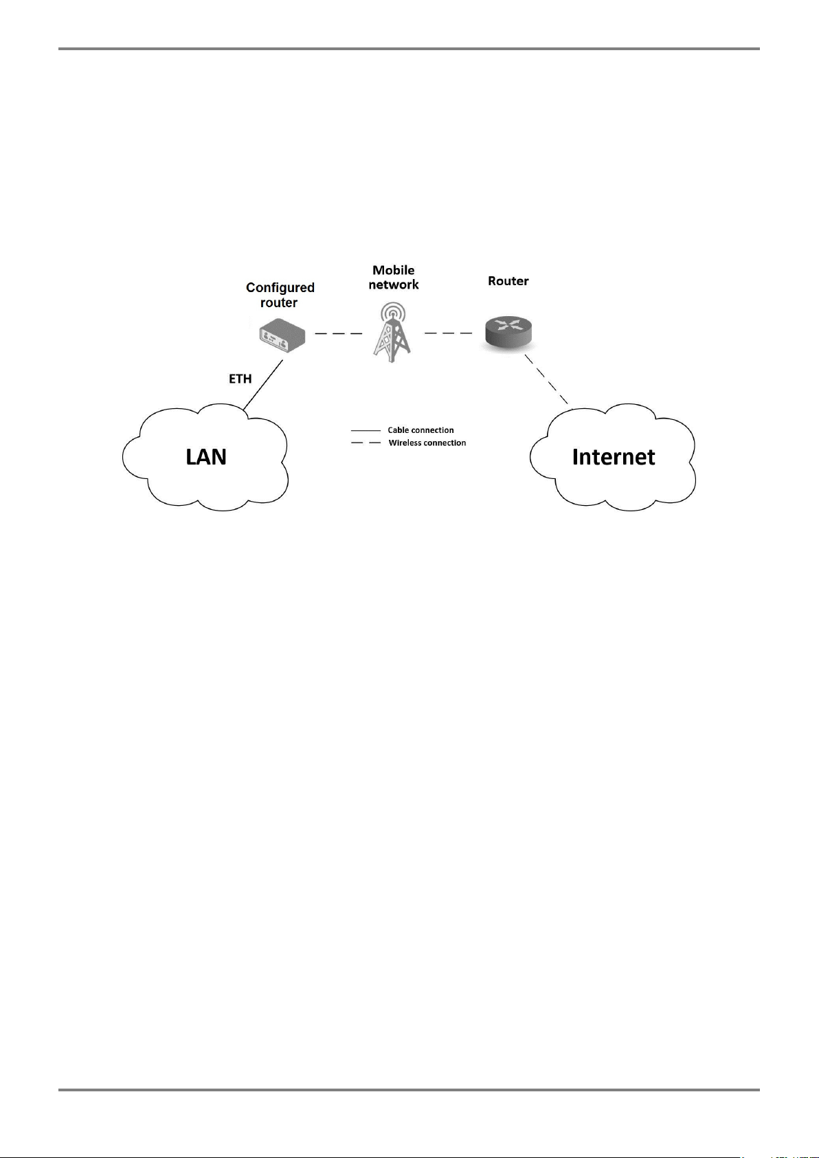
Access to the Internet from LAN
• This example illustrates a typical case when the cellular router is used to access the Internet through
the cellular network.
• Not supported by LAN routers without a cellular interface.
Figure 1: Access to the Internet from LAN
ICR-3232 Hardware Manual 2

1 Product Overview 1.2 Product Usage Examples
Backed up access to the Internet (from LAN)
• This example illustrates the function of backing up the access to the Internet for a cellular router.
• The access can be backed up by a PPPoE connection, Ethernet wired connection, or by WiFi (for
models supporting WiFi).
Figure 2: Backed up Access to the Internet
ICR-3232 Hardware Manual 3

1 Product Overview 1.2 Product Usage Examples
Secure networks interconnection or using VPN
• This example illustrates the secure VPN tunnel interconnection between the configured Advantech
router and a router of a remote network behind the Internet. The cellular network is used to connect
the configured router to the Internet.
Figure 3: Using VPN Tunnel
ICR-3232 Hardware Manual 4
1 Product Overview 1.2 Product Usage Examples
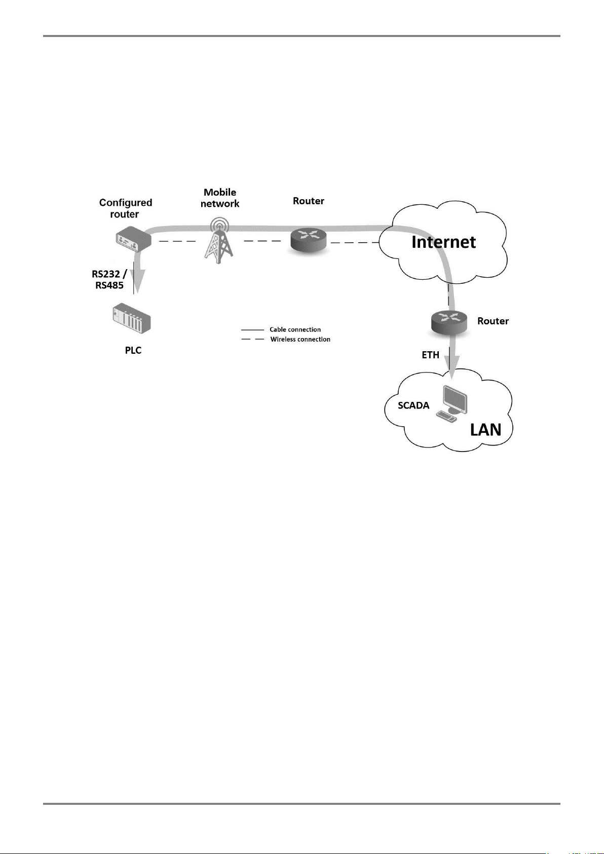
Serial Gateway
• This example illustrates the situation when the configured Advantech router provides access to a PLC
device connected by a serial interface to this router.
• The PLC device can be controlled from a remote local network running the SCADA system, for in-
stance. This device is accessible on the entire Internet network. Supported only by a router equipped
with a serial interface.
Figure 4: Serial Gateway
ICR-3232 Hardware Manual 5
1 Product Overview 1.3 Hardware Overview
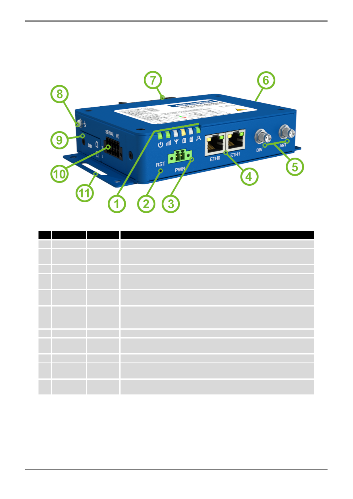
1.3 Hardware Overview
The router case preview is shown in Figure 5. A short description of hardware parts of the router is listed
in Table 1, including the links to the chapters with a detailed description.
Figure 5: Hardware Overview of the Router
# Item/CaptionType Description
1 LEDs - Status LED indication; see Chapter 2.7.
2 RST - Button to reboot the router or to restore the default
configuration; see Chapter 2.8.
3 PWR 2-pin Power supply 2-pin terminal socket; see Chapter 2.4.
4 ETH0,
ETH1
RJ45 100 MB Ethernet connection for the firts and second LAN; see Chap-
ter 2.3.
5 DIV, ANT SMA Connector for the diversity and main antennas of the cellular module;
see Chapter 2.2 and Chapter 4.4 for cellular module parameters.
6 WiFi,
GNSS
SMA,
R-SMA
One SMA connecor for the GNSS antenna and two R-SMA connectors
for the WiFi antennas. See Chapter 2.2 for more information, Chap-
ter 4.5 for GNSS parameters and Chapter 4.6 for WiFi parameters.
7 DIN clip - DIN rail clip, included as standard accessories; see Chapter 1.11.
8 Grounding
screw
M3 Pay attention to proper grounding; see Chapter 2.4.
9 SIM slots Mini SIM Two SIM card slots; see Chapter 2.1.
10 SERIAL |
I/O
10-pin
terminal
RS232, RS485, binary inputs, and binary outputs interfaces. See Chap-
ter 2.6 for more information.
11 Wall clips - Wall mounting clips, included as standard accessories; see Chap-
ter 1.10.
Table 1: Hardware Overview of the Router
ICR-3232 Hardware Manual 6

1 Product Overview 1.4 Product Versions
1.4 Product Versions
ICR-3232 router is supplied in the following versions (see table below). All versions are available in metal
box.
Router versions
SIM
BIN
BOUT
ETH
WiFi
GNSS
RS232
RS485
Version without WiFi and GNSS 2 x 1 x 1 x 2 x 1 x 1 x
Version with WiFi and GNSS 2 x 1 x 1 x 2 x 1 x 1 x 1 x 1 x
Table 2: Router versions
Figure 6: Version without WiFi and GNSS
Figure 7: Version with WiFi and GNSS
ICR-3232 Hardware Manual 7

1 Product Overview 1.5 Order Codes
1.5 Order Codes
Order codes overview is shown in the table below.
Product type Product name Order code Features – interfaces
ICR-3200 ICR-3232 ICR-3232 LTE module for ANZ, 2x ETH, 1x BI, 1x BO,
1x RS232, 1x RS485, 2x SIM reader
ICR-3200 ICR-3232 ICR-3232W LTE module for ANZ, 2x ETH, 1x BI, 1x BO,
1x RS232, 1x RS485, 2x SIM reader, WiFi,
GNSS
Table 3: Order Codes Overview
1.6 Product Revisions
For the product revision history, see the table below. The revision number is printed on the packaging
and product labels.
The router GUI can also display the product revision under Status -> General -> System Information ->
Product Revision. Please note that the default revision (Rev.1.0) is unavailable here.
Rev.# Description
1.0 Initial version (revision not printed on the labels).
2.0 New design of the mainboard; see PCN-2022-01 for details.
Table 4: HW Revisions History
ICR-3232 Hardware Manual 8

1 Product Overview 1.7 Package Contents
1.7 Package Contents
The standard set of router includes items listed in the following table:
Item# Description Figure Q’ty
1 ICR-3232 or ICR-3232W router 1 pcs
2DIN holder
(screwed on the router) 1 pcs
3Wing for wall mounting
(screwed on the router) 2 pcs
42-pin terminal block for power supply
(deployed on the router) 1 pcs
5
10-pin terminal block for RS232,
RS485 and I/O
(deployed on the router)
1 pcs
6Quick Start Guide Leaflet 1 pcs
Table 5: Contents of package
ICR-3232 Hardware Manual 9

1 Product Overview 1.8 Product Dimensions
1.8 Product Dimensions
For the dimensions of the product in metal and plastic boxes see the figures below. Note that all sizes
are measured in millimeters.
Figure 8: Basic dimensions of the router box
Figure 9: Basic dimensions of the router box
ICR-3232 Hardware Manual 10

1 Product Overview 1.9 Mounting Recommendations
1.9 Mounting Recommendations
The router can be placed:
• on a flat surface,
• on a wall (or another surface) using the side wings,
• on a DIN rail EN 60715 with the included metal DIN rail clip.
For most applications with a built-in router within a switchboard, it is possible to recognize two kinds of
environments:
• A non-public, industry environment of low voltage with high interference,
• a public environment of low voltage and without high interference.
For both of these environments, it is possible to mount the router to a switchboard, after which there is
no need to have examination immunity or issues in connection with EMC according to EN 61439-1:2011.
In compliance with the EN 61439-1:2011 specification, it is necessary to observe the following as-
sembly instructions for a router attached to a switchboard:
• For whip antennas it is recommended to observe a minimum distance of 6 cm from cables and metal
surfaces on every side in order to avoid interference. When using an external antenna separate from
the switchboard it is necessary to fit a lightning conductor.
• When mounting a router on sheet-steel we recommend using a cable antenna.
• For all cables, we recommend to bind the bunch, and for this we recommend:
–The length of the bunch (the combination of power supply and data cables) should be a max-
imum 1.5 m. If the length of data cables exceeds 1.5 m or if the cable is leading towards the
switchboard, we recommend installing surge protectors.
–Data cables must not have a reticular tension of ∼230 V/50 Hz or ∼120 V/60 Hz.
• Sufficient space must be left between each connector for the handling of cables,
• To ensure the correct functioning of the router we recommend the use of an earth-bonding distribu-
tion frame for the grounding of the power supply of the router, data cables and antenna within the
switchboard.
ICR-3232 Hardware Manual 11

1 Product Overview 1.10 Wall Mounting
1.10 Wall Mounting
The wall mounting clip is supplied with the router as standard accessories.
The router can be screwed to a wall (or another surface) using the wall mounting clips. Two wall mounting
clips are assembled to the router during the production and need to be roteted as shown of Figure 10.
There are two wholes on the clip with a diameter of 5 millimeters. For detailed information about the
mounting dimensions see Chapter 1.8.
When mounting the wall mounting clip, tighten the screws with max. torque of 0.4 Nm.
Figure 10: Rotated Wall Mounting Clips
ICR-3232 Hardware Manual 12

1 Product Overview 1.11 DIN Rail Mounting
1.11 DIN Rail Mounting
The DIN rail clip is suitable for a DIN rail according to EN 60715 standards.
When mounting the DIN rail clip, tighten the screws with max. torque of 0.4 Nm.
To remove the router from the DIN rail it is necessary to lightly push down the router so that the bottom
part of the DIN rail clip hitched to the DIN rail get out of this rail and then fold out the bottom part of the
router away from the DIN rail.
Figure 11: Removing from the DIN rail
ICR-3232 Hardware Manual 13

1 Product Overview 1.12 Product Label
1.12 Product Label
The figure below shows an example of the product labels with all the information printed on them.
Figure 12: Product Label
ICR-3232 Hardware Manual 14
Other manuals for ICR-3232
1
Table of contents
Other Advantech Industrial Equipment manuals


