Safety Precautions
MTC Coring Unit. Operator’s Manual
© 2016 Utilicor Technologies Inc.
5
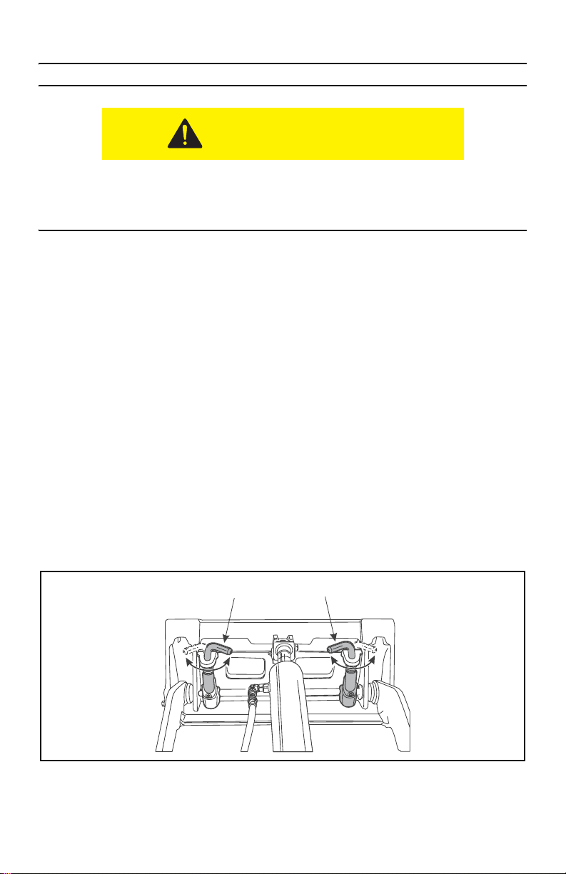
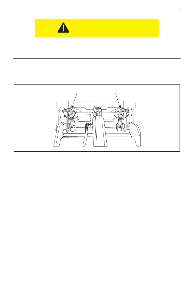
Hydraulic Hoses
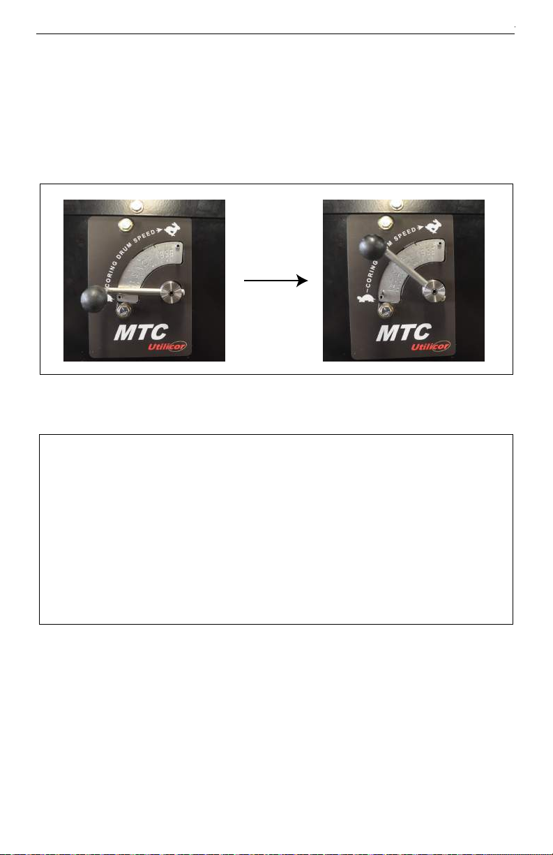
1. Cycle attachment drive control to
relieve residual pressure at
hydraulic couplers.
2. Remove dirt and debris from
hydraulic couplers.
3. Connect male coupler on attach-
ment to female coupler (3) on unit.
4. Connect female coupler on
attachment to male coupler (1) on
unit.
5. The case drain connection is not
required for this attachment (2).
6. Ensure that connections are secure
by pulling on hoses.
2
1
3
2
1
3
Pressurized fluid or air could pierce skin and cause severe injury. Refer to
operator’s manual for proper use.
To help avoid injury:
• Escaping pressurized fluid can cause injury or pierce skin.
• Before disconnecting a hydraulic line, turn engine off and operate all controls to relieve
pressure. Lower, block, or support any raised component with a hoist. Cover connection
with heavy cloth and loosen connector nut slightly to relieve residual pressure. Catch all
fluid in a container.
• Before using system, check that all connections are tight and all lines are undamaged.
• Use a piece of cardboard or wood, rather than hands, to search for leaks.
• Wear protective clothing, including gloves and eye protection.
• If you are injured, seek immediate medical attention from a doctor familiar with this type of
injury.
Hot parts may cause burns. Do not touch until cool.
To help to avoid injury:
Wear gloves when connecting and disconnecting hydraulic hoses and
wait until unit has cooled before touching hydraulic components.