manuals.online logo
Brands
  1. Home
  2. •
  3. Brands
  4. •
  5. Advantech
  6. •
  7. Motherboard
  8. •
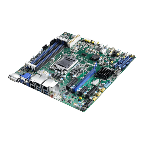
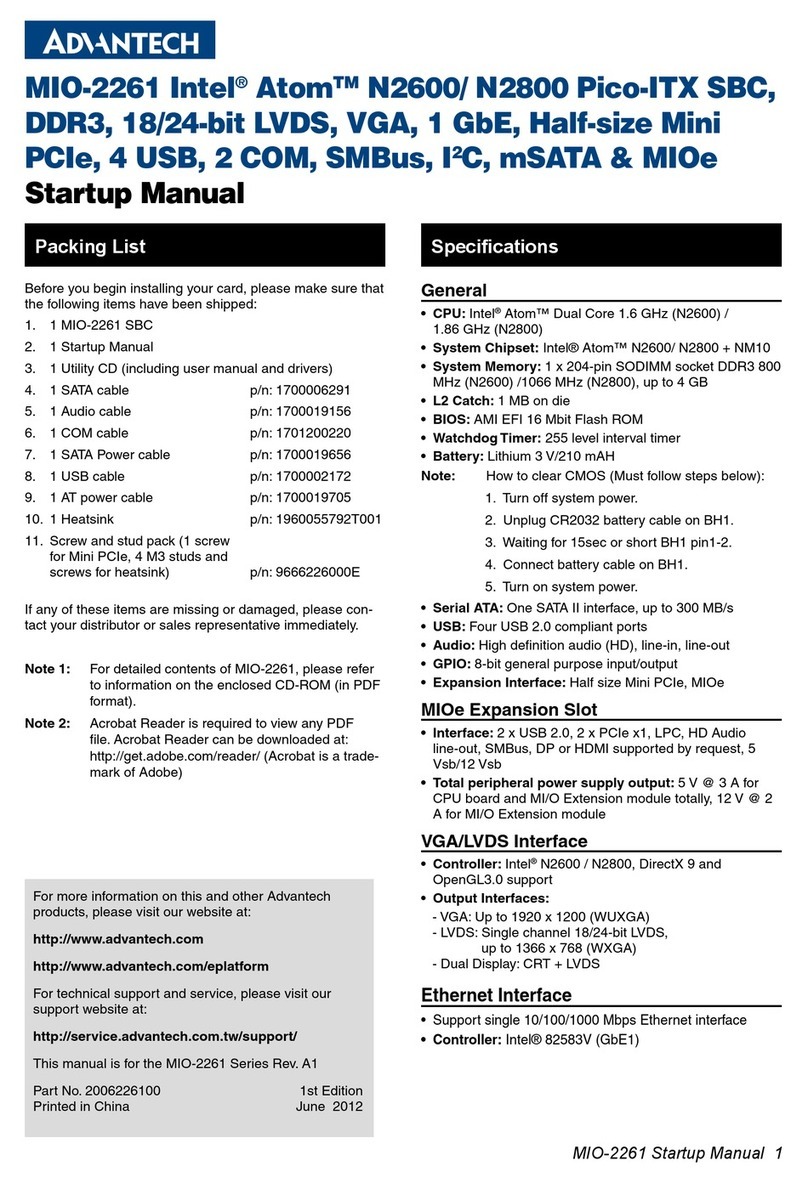
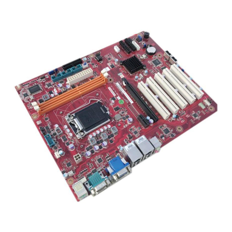
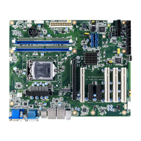
  9. Advantech AIMB-707 Installation and operation manual

Advantech AIMB-707 Installation and operation manual

Other manuals for AIMB-707

2

Other Advantech Motherboard manuals

Advantech AIMB-227 AMD Installation and operation manual

Advantech

Advantech AIMB-227 AMD Installation and operation manual

Advantech MIOe-DB2000 User manual

Advantech

Advantech MIOe-DB2000 User manual

Advantech MIO-5250 User manual

Advantech

Advantech MIO-5250 User manual

Advantech AIMB-784 User manual

Advantech

Advantech AIMB-784 User manual

Advantech PCA-6028 Installation and operation manual

Advantech

Advantech PCA-6028 Installation and operation manual

Advantech PPC-MB-8260 Installation and operation manual

Advantech

Advantech PPC-MB-8260 Installation and operation manual

Advantech AIMB-764 Installation and operation manual

Advantech

Advantech AIMB-764 Installation and operation manual

Advantech PCA-6743 Installation and operation manual

Advantech

Advantech PCA-6743 Installation and operation manual

Advantech RSB-4410 User manual

Advantech

Advantech RSB-4410 User manual

Advantech ASR-1000K-00A1E Installation and operation manual

Advantech

Advantech ASR-1000K-00A1E Installation and operation manual

Advantech PCE-7210 User manual

Advantech

Advantech PCE-7210 User manual

Advantech ACP-2010 User manual

Advantech

Advantech ACP-2010 User manual

Advantech AIMB-285 User manual

Advantech

Advantech AIMB-285 User manual

Advantech MIC-3355 User manual

Advantech

Advantech MIC-3355 User manual

Advantech PCM-4372 User manual

Advantech

Advantech PCM-4372 User manual

Advantech MIC-3329 Series User manual

Advantech

Advantech MIC-3329 Series User manual

Advantech AIMB-232 Installation and operation manual

Advantech

Advantech AIMB-232 Installation and operation manual

Advantech PCM-4862 Installation and operation manual

Advantech

Advantech PCM-4862 Installation and operation manual

Advantech PCI-7020F PCI-7020VG PCI-7020LV PCI-7020 User manual

Advantech

Advantech PCI-7020F PCI-7020VG PCI-7020LV PCI-7020 User manual

Advantech MIC-3369C User manual

Advantech

Advantech MIC-3369C User manual

Advantech SOM-4475 User manual

Advantech

Advantech SOM-4475 User manual

Advantech AIMB-340F series User manual

Advantech

Advantech AIMB-340F series User manual

Advantech AIMB-780 User manual

Advantech

Advantech AIMB-780 User manual

Advantech PCM-3362 Installation and operation manual

Advantech

Advantech PCM-3362 Installation and operation manual

Popular Motherboard manuals by other brands

Gigabyte MNJ190I-FH user manual

Gigabyte

Gigabyte MNJ190I-FH user manual

Biostar HI-FI-Z87X-3D Setup manual

Biostar

Biostar HI-FI-Z87X-3D Setup manual

Atmel SAM9753PIA-DK user guide

Atmel

Atmel SAM9753PIA-DK user guide

Coapt GEN2 Handbook

Coapt

Coapt GEN2 Handbook

Supero SUPER P4DL6 user manual

Supero

Supero SUPER P4DL6 user manual

Cypress CY3210-PSoCEVAL1 quick start guide

Cypress

Cypress CY3210-PSoCEVAL1 quick start guide

ASROCK B660M-HDV manual

ASROCK

ASROCK B660M-HDV manual

Fujitsu D2831 Short description

Fujitsu

Fujitsu D2831 Short description

Industrial Computers ADE-6050 user manual

Industrial Computers

Industrial Computers ADE-6050 user manual

Asus TUF Z270 MARK 2 manual

Asus

Asus TUF Z270 MARK 2 manual

DFI NB71-BC user manual

DFI

DFI NB71-BC user manual

ASROCK H61 Pro BTC user manual

ASROCK

ASROCK H61 Pro BTC user manual

Norco POS-7893 user manual

Norco

Norco POS-7893 user manual

Intel DG965MS specification

Intel

Intel DG965MS specification

Asus B85M-VIEW PAKER user manual

Asus

Asus B85M-VIEW PAKER user manual

Asus P5G41T-M LX V2 user manual

Asus

Asus P5G41T-M LX V2 user manual

Gigabyte GA-K8VT800-RH user manual

Gigabyte

Gigabyte GA-K8VT800-RH user manual

Gigabyte Z790M AORUS ELITE user manual

Gigabyte

Gigabyte Z790M AORUS ELITE user manual

manuals.online logo
manuals.online logoBrands
  • About & Mission
  • Contact us
  • Privacy Policy
  • Terms and Conditions

Copyright 2025 Manuals.Online. All Rights Reserved.

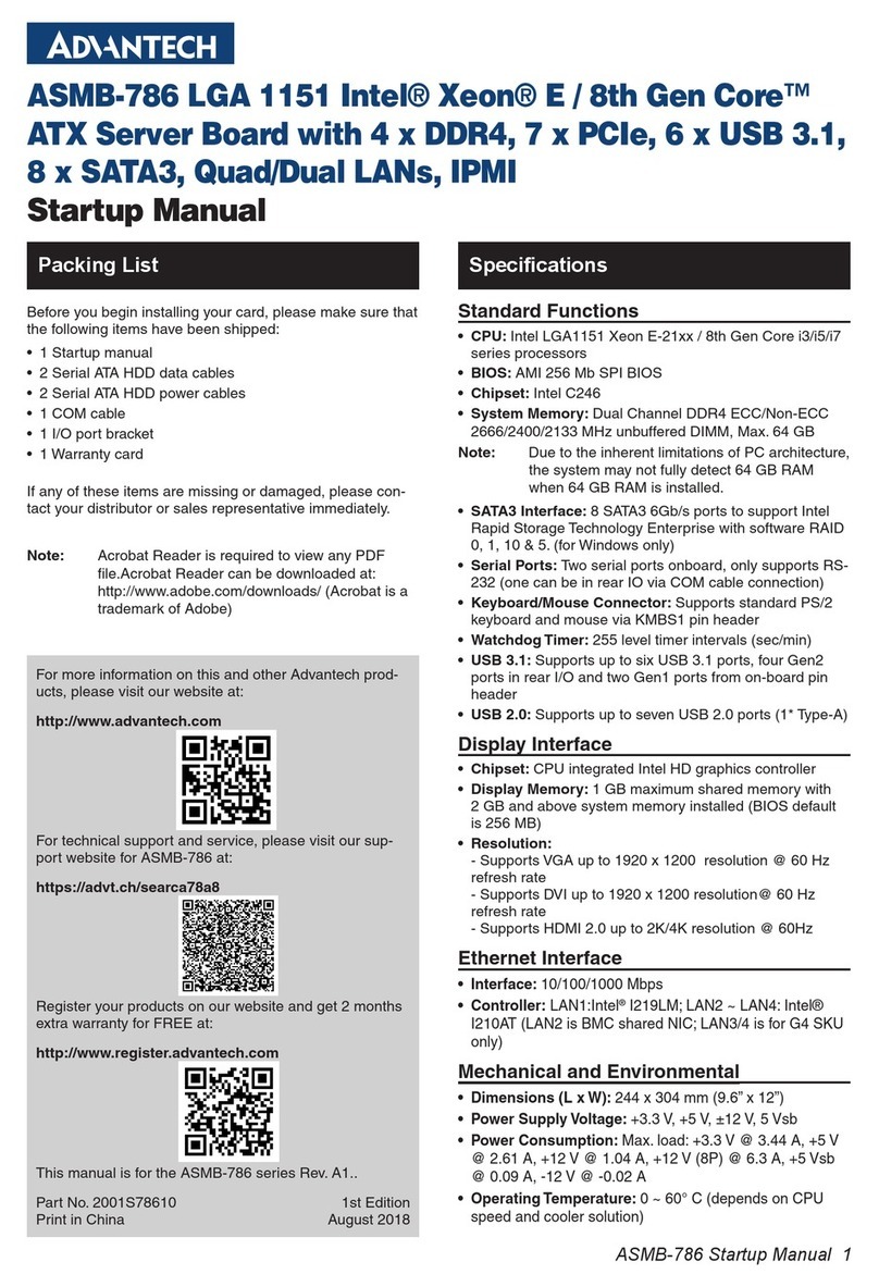
AIMB-707 Startup Manual 1
AIMB-707 LGA1200 Intel® Core™ i9/i7/i5/i3 ATX with
Dual Display, M.2, USB 3.2, and DDR4
Startup Manual
Specications (Cont.)
Packing List
For more information on this and other Advantech
products, please visit our website at:
http://www.advantech.com
For technical support and service, please visit our sup-
port website for AIMB-707 at:
http://advt.ch/aimb707spt
Register your products on our website and get 2 months
extra warranty for free at:
http://www.register.advantech.com
This manual is for the AIMB-707 series Rev. A1.
Part No. 2041070700
Printed in China
1st Edition
September 2020
• System memory: Up to 64 GB in two 288-pin DIMM
sockets supporting dual-channel DDR4 2400/2666/2933
SDRAM. AIMB-707 supports non-ECC unbu󰀨ered DIMMs
and does not support any memory conguration that
mixes non-ECC with ECC unbu󰀨ered DIMMs.
• M.2 socket: One M.2 socket supports up to PCIe x2 M-
key 2280 type storage devices.
• SATA interface: Four on-board Serial ATA 3.0 connectors
support data transmission rates up to 600 MB/s. All four
SATA 3.0 ports support Advanced Host Controller Inter-
face (AHCI) technology.
• PCIe and PCI slot: One PCIe x16 expansion slot, 2x
PCIe x4 expansion slots (x1 link), 4x PCI slots 32-bit/33
MHz PCI 2.2 compliant.
• USB 3.2/2.0: Six USB 3.2 Gen 1 ports (6 rear), 4x USB
2.0 ports (2x via header, 2x internal Type-A).
• LPC interface: Advantech-designed LPC connector sup-
ports TPM module and COM port extension modules.
• Serial port: Up to 6x serial ports: COMD1, COMD2 and
COM 4 ~ 6 are RS-232; COM3 is RS-232/422/485 with
jumper and BIOS menu options.
• Parallel port: One parallel port, which supports SPP/
EPP/ECP mode.
• Keyboard/mouse connector: The motherboard is not
equipped with rear PS/2 connector for keyboard/mouse.
A 6-pin onboard header is supported for an optional PS/2
keyboard/mouse cable.
• Watchdog timer: 255 sec timer level intervals.
Graphic Interface
• Chipset: CPU integrated graphics controller.
• Display memory: One GB maximum shared memory
with 2x GB and above system memory installed.
• DVI-D: Resolution up to 1920 x 1200 @ 60 Hz refresh
rate.
• VGA: Resolution up to 1920 x 1200 @ 60 Hz refresh rate.
Ethernet Interface
• Interface: 10/100/1000 Mbps.
• Controller: LAN1:
Intel®I219-V;
LAN2 (G2 sku only):
Intel®
I211-AT.
Mechanical and Environmental
• Dimensions (L x W): 304.8 x 244 mm (12 x 9.6 in).
• Power supply voltage: +3.3 V, +5 V, ±12 V, +5 Vsb.
• Power consumption:
Intel®Core™ i9-10900E; DDR4 32 GB x 2.
Maximum: +3.3 V at 0.72 A, +5 V at 1.29 A, +12 V at 6.5
A, +5 Vsb at 0.11 A, -12 V at 0.04 A.
• Operating temperature: 0 ~ 60 °C/32 ~ 140 °F (depend-
ing on the CPU).
• Weight of board: 0.7 kg (1.54 lb).
Before you begin installing your card, please make sure that
the following items have been shipped:
• 1x AIMB-707 Startup Manual
• 2x Serial ATA HDD data cables
• 1x I/O port bracket
If any of these items are missing or damaged, please con-
tact your distributor or sales representative immediately.
Standard Functions
• CPU: LGA1200 socket supporting 10th Gen. Intel®
Core™ i9/i7/i5/i3 and Pentium™/Celeron™ processor.
• BIOS: AMI 128 Mbit SPI BIOS.
• Chipset: Intel® H420E PCH.
Note: Legacy platforms are not supported.
Specications
2 AIMB-707 Startup Manual
The board has a number of jumpers that allow you to con-
gure your system to suit your application. The table below
lists the function of each jumper and connector.
Connector / Jumper List
Label Function
LPT1 Parallel port, supporting SPP/EPP/
ECP mode
LAN1 LAN1
LAN2 LAN2 (G2 sku only)
USB3C1, USB3C3 4x USB 3.2 Gen 1 port
USB3C2 2x USB 3.2 Gen 1 port (G2 sku
only)
USB2A1 USB 2.0 internal Type-A port
USB2A2 USB 2.0 internal Type-A port (G2
sku only)
USB2H1 2x USB 2.0 port (10-pin header)
VGA1+DVI1 VGA connector / DVI-D connector
(DVI1 for G2 sku only)
COMD1+COMD2 Serial port: RS-232 (DB-9 con-
nector)
COM4 ~ COM6 Serial port: RS-232 (9-pin header,
G2 sku only)
COM3 Serial port: RS-232/422/485 (9-pin
header, G2 sku only)
KBMS1 External keyboard/mouse connec-
tor (6-pin header)
CPUFAN1 CPU fan connector (4-pin)
SYSFAN1 ~
SYSFAN3 System fan connector (4-pin)
JFP3
Keyboard lock and power LED
Suspend: fast ash (ATX/AT)
System on: on (ATX/AT)
System o󰀨: o󰀨 (ATX/AT)
JFP2 External speaker / HDD LED con-
nector / SMBus connector
JFP1 Power switch / reset connector
AUDIO1+AUDIO2 Audio connector (Line Out, Mic In)
VOLT1 Alarm board power connector
JCASE1 Case open connector
LANLED1 Front panel LAN indicator con-
nector
NVME1 M.2 2280 M-key socket (G2 sku
only)
SATA0 ~ SATA3 Serial ATA 3.0 port
PCI1 ~ PCI4 PCI slot
PCIE1 PCIe x16 slot
PCIE2 ~ PCIE3 PCIe x4 slot (x1 link)
DIMMA1 Channel A DIMM1
DIMMB1 Channel B DIMM1
ATX12V1 ATX 12 V auxiliary power connec-
tor (for CPU)
EATXPWR1 ATX 24-pin main power connector
(for system)
SPDIF_OUT1 SPDIF audio out pin header
GPIO1 8 bit GPIO from super I/O
SMBUS1 SMBus connector from PCH
FPAUD1 Front panel audio connector
LPC1 Low pin count connector
JCMOS1: CMOS clear
JME1: Intel ME update
Closed Pins Result
1-2 *Keep CMOS data
*ME normal mode
2-3
Clear CMOS data
ME recovery mode
* Default
*Keep CMOS data Clear CMOS data
*ME normal mode ME recovery mode
JWDT1+JOBS1: Watchdog timer output and OBS alarm
Closed Pins Result
2-4, 8-10 Watchdog timer disable (2-4)
OBS beep (8-10)
4-6, 8-10 *Watchdog timer reset (4-6)
OBS beep (8-10)
* Default
Watchdog timer disable (2-4) *Watchdog timer reset (4-6)
OBS beep (8-10) OBS beep (8-10)
1 2 3
1 2 3
Jumpers and Connectors Jumpers and Connectors (Cont.)
AIMB-707 Startup Manual 3
PSON1: ATX/AT mode selection
Closed Pins Result
1-2 AT mode
2-3 *ATX mode
* Default
AT mode *ATX mode
JUSB_1 (rear USB), JUSB_2 (onboard USB): USB power
source switch between +5V and +5V_DUAL
Closed Pins Result
1-2 *USB +5V_DUAL power
2-3 USB +5V power
* Default
*USB +5 V_DUAL power USB +5 V power
JSETCOM3: COM3 RS-232/422/485 jumper setting
Closed Pins Result
5-6, 7-9, 8-10,
13-15, 14-16 *RS-232
3-4, 9-11,
10-12, 15-17,
16-18
RS-422
1-2, 9-11,
10-12, 15-17,
16-18
RS-485
* Default
1 2 3
1 2 3
1 2 3
1 2 3
Note: BIOS setting changes are necessary if RS-422
or RS-485 is selected. Please refer to Chapter 3
of user manual for further settings.
JT1(TX signal), JR1(RX signal): COM3 RS-422/485
termination resistor
Closed Pins Result
1-2 Disable termination
2-3 *Enable termination
* Default
Disable termination *Enable termination
JFV1: VGA dummy load setting
Closed Pins Result
1-2 Enable VGA dummy load
2-3 *Disable VGA dummy load
* Default
Enable VGA dummy load *Disable VGA dummy load
Note: We reccomend leaving this function disabled if
you use DVI/DP as your main display.
SMB1 (clock), SMB2 (data): PCIe SMBus connection
setting
Closed Pins Result
1-2 *Enable PCIe SMBus connection
2-3
Disable PCIe SMBus connection
* Default
*Enable PCIe SMBus connection Disable PCIe SMBus connection
Note: Both SMB1 and SMB2 jumpers should be
switched to the same setting, either 1-2 closed
or 2-3 closed.
1 2 3
1 2 3
1 2 3
1 2 3
1 2 3
1 2 3
Jumpers and Connectors (Cont.) Jumpers and Connectors (Cont.)
4 AIMB-707 Startup Manual
Declaration of Conformity
Board Layout
This device complies with the requirements in Part 15 of the FCC rules. Operation is subject to the following two conditions:
1. This device may not cause harmful interference.
2. This device must accept any interference received, including interference that may cause undesired operation.
Caution! The computer is supplied with a battery-powered realtime clock circuit. There is a danger of explosion if battery
is incorrectly replaced. Replace only with same or equivalent type recommended by the manufacturer. Discard
used batteries according to manufacturer’s instructions.
Part Number Chipset Display USB 3.2 Gen 1 USB 2.0 COM GbE LAN M.2
AIMB-707G2-00A1 H420E VGA + DVI 6 4 6 2 1
AIMB-707VG-00A1 H420E VGA 4 3 2 1 0
SATA1 SATA3
SATA0 SATA2
DIMMB1
DIMMA1
PCI3
PCIE3
PCIE1
Intel H420E PCH
Intel LGA1200 Core i9/i7/i5/i3
USB2A1
COM3
USB2H1
AUDIO1+AUDIO2
LAN2
USB3C2
LAN1
USB3C1
VGA1
DVI1
COMD1
COMD2
SYSFAN1
SYSFAN3
VOLT1 EATXPWR1 PSON1 GPIO1
LPT1
SMBUS1
JCASE1
COM4
COM5
COM6
LPC1
JT1, JR1
JWDT1+JOBS1 JFP3
JFP1+JFP2
CPUFAN1
PCI1
PCIE2
PCI2
PCI4
SPDIF_OUT1 FPAUD1
KBMS1
SYSFAN2
ATX12V1
JUSB_1
JFV1
USB3C3
LANLED1
SMB1, SMB2
JUSB_2
JCMOS1
JME1
USB2A2
JSETCOM3
NVME1
3 6 9 12
25811
PWRSW RESET
HDDLED
SNMP
JFP1
&
2 5 8 11
1 4 7 10
HDDLED
SM_BUS
SPEAKER
JFP2
&
PWRLED & KEYLOCK
12345
JFP3
Figure 1: Board Layout: Jumper and
Connector Locations
Order Information