manuals.online logo
Brands
  1. Home
  2. •
  3. Brands
  4. •
  5. Advantech
  6. •
  7. PCI Card
  8. •
  9. Advantech PCI-1750 User manual

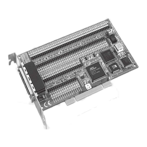
Advantech PCI-1750 User manual

PCI-1750
32-channel Isolated
Digital I/O Card
User's Manual
Copyright
This documentation and the software included with this product are
copyrighted 1998 by Advantech Co., Ltd. All rights are reserved.
Advantech Co., Ltd. reserves the right to make improvements in the
products described in this manual at any time without notice.
No part of this manual may be reproduced, copied, translated or
transmitted in any form or by any means without the prior written
permission of Advantech Co., Ltd. Information provided in this
manual is intended to be accurate and reliable. However, Advantech
Co., Ltd. assumes no responsibility for its use, nor for any infringe-
ments of the rights of third parties which may result from its use.
Acknowledgments
PC-LabCard is a trademark of Advantech Co., Ltd. IBM and PC are
trademarks of International Business Machines Corporation. MS-
DOS, Windows, Microsoft C and Quick BASIC are trademarks of
Microsoft Corporation. BASIC is a trademark of Dartmouth College.
Intel is a trademark of Intel Corporation. TURBO C is a trademark of
Borland International.
CE notification
The PCI-1750, developed by ADVANTECH CO., LTD., has passed
the CE test for environmental specifications when shielded cables are
used for external wiring. We recommend the use of shielded cables.
This kind of cable is available from Advantech. Please contact your
local supplier for ordering information.
Printed in Taiwan August 1998
Part No. 2003175000 1st Edition
ContentsContents
ContentsContents
Contents
ChapterChapter
ChapterChapter
Chapter 1: General Information1: General Information
1: General Information1: General Information
1: General Information ....................................................
....................................................
.......................... 11
11
1
IntroductionIntroduction
Introduction ..........................................................................................................................................
..........................................................................................................................................
..................................................................... 22
22
2
ChapterChapter
ChapterChapter
Chapter 2: Installation2: Installation
2: Installation2: Installation
2: Installation ..................................................................................
..................................................................................
......................................... 55
55
5
Initial InspectionInitial Inspection
Initial Inspection ..............................................................................................................................
..............................................................................................................................
............................................................... 66
66
6
UnpackingUnpacking
UnpackingUnpacking
Unpacking ................................................................................................................................................
................................................................................................................................................
........................................................................ 66
66
6
Location of ConnectorsLocation of Connectors
Location of Connectors ..........................................................................................................
..........................................................................................................
..................................................... 77
77
7
PCI-1750 Block DiagramPCI-1750 Block Diagram
PCI-1750 Block Diagram ......................................................................................................
......................................................................................................
................................................... 88
88
8
Connector Pin AssignmentsConnector Pin Assignments
Connector Pin Assignments ..............................................................................................
..............................................................................................
............................................... 99
99
9
Installation InstructionsInstallation Instructions
Installation Instructions ......................................................................................................
......................................................................................................
...................................................1010
1010
10
ChapterChapter
ChapterChapter
Chapter 3: Operation3: Operation
3: Operation3: Operation
3: Operation ....................................................................................
....................................................................................
..........................................1111
1111
11
OperationOperation
OperationOperation
Operation ................................................................................................................................................
................................................................................................................................................
........................................................................1212
1212
12
Isolated Digital I/O PortsIsolated Digital I/O Ports
Isolated Digital I/O Ports ....................................................................................................
....................................................................................................
..................................................1212
1212
12
Timer and CounterTimer and Counter
Timer and Counter ....................................................................................................................
....................................................................................................................
..........................................................1414
1414
14
Interrupt FunctionInterrupt Function
Interrupt Function ......................................................................................................................
......................................................................................................................
...........................................................1616
1616
16
AppendixAppendix
AppendixAppendix
Appendix A: Function of 8254 Counter ChipA: Function of 8254 Counter Chip
A: Function of 8254 Counter ChipA: Function of 8254 Counter Chip
A: Function of 8254 Counter Chip ............
............
......1919
1919
19
AppendixAppendix
AppendixAppendix
Appendix B: Register Format of PCI-1750B: Register Format of PCI-1750
B: Register Format of PCI-1750B: Register Format of PCI-1750
B: Register Format of PCI-1750 ....................
....................
..........2727
2727
27
Chapter 1 General Information 11
11
1
1
General Information
CHAPTER
22
22
2 PCI-1750 User's Manual
Introduction
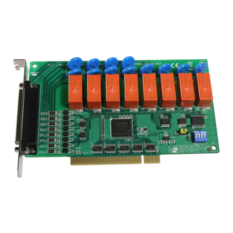
The PCI-1750 offers 16 isolated digital input channels, 16 isolated
digital output channels, one isolated counter and one timer with PCI
bus interface. With isolation protection of 2500 VDC
the PCI-1750 is
ideal for industrial applications where high-voltage protection is
required.
The card's 16 bits are divided into two 8-bit I/O ports. This makes the
PCI-1750 very easy to program. This card also offers dual interrupt
handling capability, providing the user more flexibility in using the
counter, timer, digital inputs or a combination to generate interrupts to
the PC. A user can easily configure the interrupts through software.
The PCI-1750 uses a PCI controller to interface the card to the PCI
bus. The controller fully implements the PCI bus specification Rev
2.1. All bus relative configurations, such as base addresses and
interrupt assignments, are automatically controlled by software. No
jumpers or DIP switches are required for user configuration .
Numbering Convention
All numbers given in this manual are in decimal format unless
specifically noted otherwise. In particular, where a register address is
given as (Base + 32), the decimal number "32" should be added to the
base value.
Features
• 16 isolated digital input and 16 isolated digital output channels.
• High voltage isolation on all channels (2500 VDC
)
• High sink current on isolated output channels (200 mA/Channel).
• D-type 37-pin female connector.
• Supports dry contact or 5 to 48 VDC
isolated input.
Chapter 1 General Information 33
33
3
• Dual interrupt handling capability
• Timer / Counter interrupt capability generates watchdog timer
interrupts
Applications
• Digital I/O control.
• Industrial ON/OFF control.
• Industrial and lab automation.
• Switch status sensing
• BCD interfacing.
Specifications
16 Optically-Isolated Inputs:16 Optically-Isolated Inputs:
16 Optically-Isolated Inputs:
•Input range :Input range :
Input range :Input range :
Input range : 5 to 48 VDC
or dry contact.
•Isolation voltage :Isolation voltage :
Isolation voltage :Isolation voltage :
Isolation voltage : 2,500 VDC
•Throughput :Throughput :
Throughput :Throughput :
Throughput : 10 KHz
16 Optically-Isolated Outputs:16 Optically-Isolated Outputs:
16 Optically-Isolated Outputs:
•Output range :Output range :
Output range :Output range :
Output range : Open collector 5 to 40 VDC
•Sink Current :Sink Current :
Sink Current :Sink Current :
Sink Current : 200 mA Max.
•Isolation voltage :Isolation voltage :
Isolation voltage :Isolation voltage :
Isolation voltage : 2,500 VDC
•Throughput :Throughput :
Throughput :Throughput :
Throughput : 10 KHz
One 16-bit Optically-Isolated Counter:One 16-bit Optically-Isolated Counter:
One 16-bit Optically-Isolated Counter:
• Shares Pin with isolated input 15.
•Throughput :Throughput :
Throughput :Throughput :
Throughput : 1 MHz Max.
•Isolation voltage :Isolation voltage :
Isolation voltage :Isolation voltage :
Isolation voltage : 2,500 VDC
One 32-bit Timer.One 32-bit Timer.
One 32-bit Timer.
• 10 MHz internal clock source
44
44
4 PCI-1750 User's Manual
Interrupt SourceInterrupt Source
Interrupt Source
• Isolated Input 0, 4, 8, 12, Counter and Timer.
Dimensions:Dimensions:
Dimensions: 175 mm x 100 mm (6.9" x 3.9")
Connectors:Connectors:
Connectors: One DB-37 female connector
One 2-pin terminal block for extended ground
Power consumption:Power consumption:
Power consumption: 5 V @ 850 mA (Typical)
5 V @ 1.0 A (Max.)
Operating temperature:Operating temperature:
Operating temperature: 0 ~ 70º C (32º F ~ 158º F)
Storage temperature:Storage temperature:
Storage temperature: -20 ~ 80º C (-4º F ~ 176º F)
Humidity:Humidity:
Humidity:Humidity:
Humidity: 5% ~ 95% non-condensing
Chapter 2 Installation 55
55
5
2
Installation
CHAPTER
66
66
6 PCI-1750 User's Manual
Initial Inspection
Before starting to install the PCI-1750, make sure there is no visible
damage on the card. We carefully inspected the card both mechani-
cally and electrically before shipment. It should be free of marks and
in perfect order on receipt.
As you unpack the PCI-1750, check it for signs of shipping damage
(damaged box, scratches, dents, etc.) If it is damaged or fails to meet
specification, notify our service department or your local sales
representative immediately. Also, call the carrier immediately and
retain the shipping carton and packing materials for inspection by the
carrier. We will then make arrangements to repair or replace the unit.
Unpacking
The PCI-1750 contains components that are sensitive and vulnerable
to static electricity. Discharge any static electricity on your body to
ground by touching the back of the system unit (grounded metal)
before you touch the board.
Remove the PCI-1750 card from its protective packaging by grasping
the rear panel. Handle the card only by its edges to avoid static
discharge which could damage its integrated circuits. Keep the
antistatic package. Whenever you remove the card from the PC,
please store the card in this package for its protection.
You should also avoid contact with materials that hold static electrici-
ty such as plastic, vinyl and styrofoam.
Check the product contents inside the packing. There should be one
card, one CD-ROM, and this manual. Make sure nothing is missing.
Chapter 2 Installation 77
77
7
Location of Connectors
Figure 2.1 shows the names and locations of connectors on the board.
The PCI-1750 is a plug and play device. The PCI BIOS assigns the
system resources automatically at system start-up. All functions can
be set by software. No jumpers or switches are used on this card.
Figure 2.1: Board connectorsFigure 2.1: Board connectors
Figure 2.1: Board connectors
88
88
8 PCI-1750 User's Manual
Figure 2.2: Block DiagramFigure 2.2: Block Diagram
Figure 2.2: Block Diagram
PCI-1750 Block Diagram
Counter Counter 2
IDI 8~15
IDO 8~15
IDO 0~7
IDI 0~7
Interrupt
Control
Logic
Chapter 2 Installation 99
99
9
Connector Pin Assignments
Description of pin use:Description of pin use:
Description of pin use:
IDI 0 ~ IDI 15:IDI 0 ~ IDI 15:
IDI 0 ~ IDI 15: Isolated digital input pins
IDO 0 ~ IDO 15:IDO 0 ~ IDO 15:
IDO 0 ~ IDO 15: Isolated digital output pins
IGND:IGND:
IGND:IGND:
IGND: Isolated ground
COM1:COM1:
COM1:COM1:
COM1: Common pin for connecting inductive loads of isolated output
channels IDO 0 ~ IDO 7
COM2:COM2:
COM2:COM2:
COM2: Common pin for connecting inductive loads of isolated output
channels IDO 8 ~ IDO 15
Counter2:Counter2:
Counter2:Counter2:
Counter2: Input pin of isolated counter (shared with IDI 15)
Warning: Be careful when wiring digital input lines. Never apply a
negative voltage to the isolated input pins, as this may
damagethePCI-1750.
IDO 4
1
2
3
4
5
8
7
6
9
10
11
12
13
14
15
16
17
18
19
20
21
22
23
24
25
26
27
28
29
30
31
32
33
34
35
36
37
IDI 0
IDI 2
IDI 4
IDI 6
IDI 8
IDI 10
IDI 12
IGND
COM1
IDI 14
IDO 0
IDO 6
IDO 8
IDO 10
IDO 12
IDO 14
COM2 IDO 15
IDO 13
IDO 11
IDO 7
IDO 3
IDO 1
IGND
IGND
IDI 15/Counter2
IDI 13
IDI 11
IDI 9
IDI 7
IDI 5
IDI 3
IDI 1
IDO 5
IDO 9
IDO 2
1010
1010
10 PCI-1750 User's Manual
Installation Instructions
The PCI-1750 can be installed in any PCI slot in the computer. How e v-
er,refer to the computer user's manual to avoid any mistakes and
danger before you follow the installation procedure below:
1. Turn off your computer and any accessories connected to the
computer.
Warning: TURNOFFyourcomputerpower supply whenever
you install or remove any card, or connect and
disconnect cables.
2. Disconnect the power cord and any other cables from the back of
the computer
3. Removethe cover of the computer.
4. Select an empty 5 V PCI slot. Remove the screw that secures the
expansion slot cover to the system unit. Save the screw to secure
the interface card retaining bracket.
5. Carefully grasp the upper edge of the PCI-1750. Align the hole in
the retaining bracket with the hole on the expansion slot and align
the gold striped edge connector with the expansion slot socket.
Press the card into the socket gently but firmly. Make sure the card
fits the slot tightly.
6. Secure the PCI-1750 by screwing the mounting bracket to the back
panel of computer.
7. Attach any accessories (cable, wiring terminal, etc.) to the card.
8. Replace the coverofyour computer. Connect the cablesyou
removed in step 2.
9. Turn the computer power on.
Chapter 3 Function Description 1111
1111
11
3
Operation
CHAPTER
1212
1212
12 PCI-1750 User's Manual
Operation
This chapter describes the operation of the PCI-1750. The driver
software provided allows a user to access all of the card's functions
without register level programming. Please see the User's Manual for
the driver bundled with this card for more information. For users who
prefer to implement their own bit-level programming to drive the
card's functions, information useful for making such a program is
included in this chapter.
Isolated Digital I/O Ports
Introduction
The PCI-1750 has 16 isolated digital input channels designated
IDI 0 ~ IDI 15, and 16 isolated digital output channels designated
IDO 0 ~ IDO 15. Data can be read from or written to the card's
channels.
Interrupt function of the DIO signals
TwoI/O channels (IDI 0 and IDI 8) can be used to generate hard ware
interrupts. A user can program the interrupt control register [Base +
(32Dec)] to select the interrupt sources. Refer to Section "Interrupt
Function" for details about interrupt control.
Power On Configuration
The default configuration after power on, hardware reset or software
reset is to set all the isolated output channels to low so that users need
not worry about damaging external devices during system start up or
reset.
Chapter 3 Function Description 1313
1313
13
Isolated Inputs
Each of 16 isolated digital input channels accepts dry contacts or 5 ~
48 VDC
voltage inputs. All sixteen input channels share 3 ground pins
and one extended ground terminal block (CN5).
Figure 3.1 shows how to connect an external input source to one of
the card's isolated input channels.
Warning! Be careful when wiring digital input cables. Never
apply a negative voltage to an isolated input pin, as
this may damage the PCI-1750.
Note for wet contacts:Note for wet contacts:
Note for wet contacts: A malfunction might occur in cases where the
internal resistance of a voltage source under wet contacts is significant
(>5 kW ). It is advisable to connect a parallel 5 kW ,0.5 W resistor to
avoid a voltage rise inside the voltage source.
5 K
Ω
0.5 W
ISO 5V PC 5V
Figure 3.1: Connecting external input sourceFigure 3.1: Connecting external input source
Figure 3.1: Connecting external input source
Isolated Outputs
Each of 16 isolated digital output channels comes equipped with a
Darlington transistor. Every eight output channels share common
collectors and integral suppression diodes for inductive loads.
Channels 0 ~ 7 use COM1, and channels 8 ~ 15 use COM2 as a
common pin.
1414
1414
14 PCI-1750 User's Manual
Note:
If an external voltage (5 ~ 48 V) is applied to an isolated output
channel (IDO 0 ~ IDO 15) while it is being used as an output
channel, the current will flow from the external voltage source
to the card. Please take care that the current through each GND
pin not exceed 200 mA. Use the extended ground connector
CN5 to shunt the current to the external voltage source ground.
Figure 3.2 shows how to connect an external output load to the card's
isolated outputs.
Figure 3.2: Connecting an external output loadFigure 3.2: Connecting an external output load
Figure 3.2: Connecting an external output load
Timer and Counter
Introduction
The PCL-1750 includes one 8254 compatible programmable timer/
counter chip which provides two 16-bit timers and one counter,
designated as Timer 0, Timer 1 and Counter 2. Timer 0 and Timer 1
are cascaded to be a 32-bit timer, with its input connected to a 10
MHz oscillator and its gate control pulled high (enabled). Counter 2
of the 8254 chip is a 16-bit high-speed (1 MHz) isolated event counter
(it shares a pin with isolated IDI 15). The block diagram of the timer/
counter system of PCI-1750 is shown in Figure 3.3.
Chapter 3 Function Description 1515
1515
15
Timers 0 and 1 are usually set in mode 3 (square wave generator) to
generate periodic watchdog interrupts. Counter 2 can be set in mode
0 (stop on terminal count) for measuring frequency, or in mode 3
(square wave generator) to generate periodic watchdog interrupts or to
be used as an event counter. For more details on the operating modes
of the 8254 counter chip, please refer to Appendix A.
Figure 3.3: Block diagram of timer/counterFigure 3.3: Block diagram of timer/counter
Figure 3.3: Block diagram of timer/counter
Timer/Counter Frequency and Interrupt
The input clock frequency of the counter/timers is 10 MHz. The output
of both Timer 1 and Counter 2 can generate interrupts to the system
(refer to Section 3.3). The maximum and minimum timer interrupt
frequency is (10 MHz)/(2x2)=(2.5 MHz) and (10 MHz)/
(65535*65535)=0.002328 Hz, respectively.
1616
1616
16 PCI-1750 User's Manual
tpurretnI #ecruoS 1puorGtpurretnI0puorGtpurretnI
#tiB7D6D5D4D3D2D1D0D
noitaiverbbA1F1E11M01M0F0E10M00M
The gates of the counter/timersareinter nally pulled to +5 V,keeping
the gate control always enabled.
Interrupt Function
Introduction
Four input channels (IDI 0, IDI 4, IDI 8 and IDI 12) and the output of
Timer 1 and Counter 2 are connected to the interrupt circuitry. The
"Interrupt Control Register" of the PCI-1750 controls how the
combination of the six signals generates an interrupt. Two interrupt
request signals, designated "interrupt group 0" and "interrupt group
1", can be generated at the same time, and then the software can
service these two request signals by ISR. IDI 0, IDI 4 and Timer 1 are
connected to interrupt port 0, IDI 8, IDI 12 and Counter 2 are con-
nected to interrupt port 1. The dual interrupt sources provide the card
with more capability and flexibility.
IRQ Level
The IRQ level is set automatically by the PCI plug and play BIOS and
is saved in the PCI controller. There is no need for users to set the
IRQ level. Only one IRQ level is used by this card, although it has
two interrupt sources.
Interrupt Control Register [Base + 32(Dec)]
The "Interrupt Control Register" [Base + 32(Dec)] controls the
interr upt signal source, edge and flag.Ta ble 3.1 shows the bit map of
theinterrupt controlr egister.Theregisterisareadable/writable
register.When writingtoit, it is used as a contr olregister,and when
reading from it, itisusedasastatusr egister.
TT
TT
T
aa
aa
able3.1:Interrble3.1:Interr
ble3.1:Interrble3.1:Interr
ble3.1:Interrupt contrupt contr
upt contrupt contr
upt controlrolr
olrolr
olregeg
egeg
egister bit maister bit ma
ister bit maister bit ma
ister bit ma pp
pp
p
Chapter 3 Function Description 1717
1717
17
M00 and M01:M00 and M01:
M00 and M01: "mode bits" of interrupt Group 0
M10 and M11:M10 and M11:
M10 and M11: "mode bits" of interr upt Group 1
E0,E1:E0,E1:
E0,E1:E0,E1:
E0,E1: triggering edge control bits
F0, F1:F0, F1:
F0, F1:F0, F1:
F0, F1: flag bits
Interrupt Source Control
The "mode bits" written into the interrupt control register determine
the allowable sources of signals generating an interrupt. Bit 0 and bit
1 determine the interrupt source for interrupt group 0, and bit 4 and bit
5 determine the interrupt source for interrupt group 1, as indicated in
Figure 3.4. Table 3.2 shows the relationship between an interrupt
source and the values in the mode bits.
Figure 3.4: Interrupt source controlFigure 3.4: Interrupt source control
Figure 3.4: Interrupt source control

Other manuals for PCI-1750

1

Other Advantech PCI Card manuals

Advantech PCIE-1762H User manual

Advantech

Advantech PCIE-1762H User manual

Advantech PCIE-1744 User manual

Advantech

Advantech PCIE-1744 User manual

Advantech PCI-1202 User manual

Advantech

Advantech PCI-1202 User manual

Advantech PCI-1752 User manual

Advantech

Advantech PCI-1752 User manual

Advantech MIC-3758DIO User manual

Advantech

Advantech MIC-3758DIO User manual

Advantech PCA-6008G2 User manual

Advantech

Advantech PCA-6008G2 User manual

Advantech PCIE-1752 User manual

Advantech

Advantech PCIE-1752 User manual

Advantech PCI-1742U User manual

Advantech

Advantech PCI-1742U User manual

Advantech PCIE-1802 User manual

Advantech

Advantech PCIE-1802 User manual

Advantech PCIE-1754 User manual

Advantech

Advantech PCIE-1754 User manual

Advantech PCIE-1750U User manual

Advantech

Advantech PCIE-1750U User manual

Advantech PCI-1706U User manual

Advantech

Advantech PCI-1706U User manual

Advantech PCA-6008VG User manual

Advantech

Advantech PCA-6008VG User manual

Advantech PCIE-1765 User manual

Advantech

Advantech PCIE-1765 User manual

Advantech PCI-1758 Series User manual

Advantech

Advantech PCI-1758 Series User manual

Advantech PCI-1712 Installation and operation manual

Advantech

Advantech PCI-1712 Installation and operation manual

Advantech PCI-1780 User manual

Advantech

Advantech PCI-1780 User manual

Advantech PCI-1711 User manual

Advantech

Advantech PCI-1711 User manual

Advantech PCA-6184VE User manual

Advantech

Advantech PCA-6184VE User manual

Advantech PCM-2604C-AE Installation and operation manual

Advantech

Advantech PCM-2604C-AE Installation and operation manual

Advantech DVP-7010BE User manual

Advantech

Advantech DVP-7010BE User manual

Advantech PCIE-1753 User manual

Advantech

Advantech PCIE-1753 User manual

Advantech PCI-1733 Installation and operation manual

Advantech

Advantech PCI-1733 Installation and operation manual

Advantech PCM-28P1AD Installation and operation manual

Advantech

Advantech PCM-28P1AD Installation and operation manual

Popular PCI Card manuals by other brands

ADLINK Technology PCI-8570 user manual

ADLINK Technology

ADLINK Technology PCI-8570 user manual

Manhattan 160391 user manual

Manhattan

Manhattan 160391 user manual

StarTech.com PCI1PECPDV instruction manual

StarTech.com

StarTech.com PCI1PECPDV instruction manual

Addonics Technologies AD2SA6GPX1 user guide

Addonics Technologies

Addonics Technologies AD2SA6GPX1 user guide

osprey video RM12G-1 user guide

osprey video

osprey video RM12G-1 user guide

SilverStone EC05 manual

SilverStone

SilverStone EC05 manual

AXIOMTEK AC5426P user manual

AXIOMTEK

AXIOMTEK AC5426P user manual

ATCOM AX1D Product guide

ATCOM

ATCOM AX1D Product guide

Cloud CDI-S200 Installation & setup guide

Cloud

Cloud CDI-S200 Installation & setup guide

Quatech PCD-B/UPCI-E Specifications

Quatech

Quatech PCD-B/UPCI-E Specifications

SMC Networks SMC EZ Connect g MIMO Wireless PCI Adapter... Quick installation guide

SMC Networks

SMC Networks SMC EZ Connect g MIMO Wireless PCI Adapter... Quick installation guide

Adaptec 29320ALP-R - SCSI Card Storage Controller U320 320... installation guide

Adaptec

Adaptec 29320ALP-R - SCSI Card Storage Controller U320 320... installation guide

Seada SD-HU user manual

Seada

Seada SD-HU user manual

ZyXEL Communications G-360 user guide

ZyXEL Communications

ZyXEL Communications G-360 user guide

Sun Microsystems SunATM 3U Installation and user guide

Sun Microsystems

Sun Microsystems SunATM 3U Installation and user guide

Moxa Technologies CP-114UL Series Quick installation guide

Moxa Technologies

Moxa Technologies CP-114UL Series Quick installation guide

PMC Adaptec AHA-3944-AUWD Simple Step-by-Step Tips

PMC

PMC Adaptec AHA-3944-AUWD Simple Step-by-Step Tips

ICS Advent AOB8/16 product manual

ICS Advent

ICS Advent AOB8/16 product manual

manuals.online logo
manuals.online logoBrands
  • About & Mission
  • Contact us
  • Privacy Policy
  • Terms and Conditions

Copyright 2025 Manuals.Online. All Rights Reserved.