MIKSTER MIKSTER
Controller setup
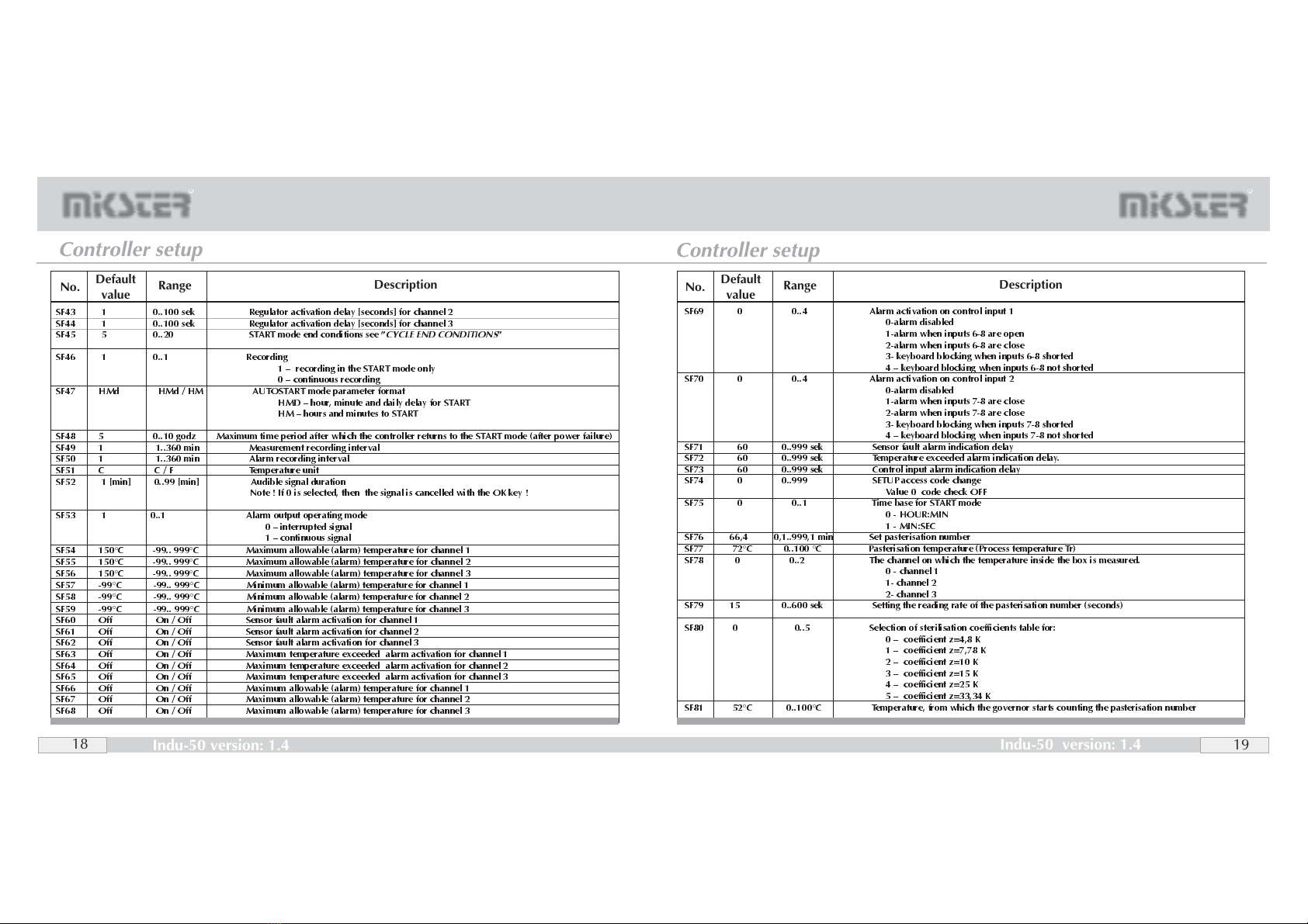
Controller setup
To get into the SETUP menu, press and hold down the key and then press the key. After
entering the access code you can change the controller parameters.
CONTROLLER SETUP
No. Description
Default
value Range
MODBUS network address
Baud rate
0 9600 ,1 19200, 2 38400,3 57600,4 115200
Channel 1 easuring input type
0 PT-500, 1 PT-100, 2 PT1000, 3 0..20 A*, 4 4..20 A*
5 ther ocouple s**, 6 ther ocouple b**, 7 ther ocouple r**, 8 ther ocouple t**
9 ther ocouple j**, 10 ther ocouple e**, 11 ther ocouple k**, 12 ther ocouple n**
* current input version, ** ther ocouple operation version
SF3 1 0..12 Measuring input type for channel 2
SF2 1 0..12
SF1 0 0..4
SF0 1 0..128
SF4 1 0..12 Measuring input type for channel 3
SF5 0 -99,0 .. 999 C Value corresponding to 0 A for channel 1 0..20 A input
°°
C
SF6 200 -99,0 .. 999 C Value corresponding to 20 A 1 0..20 A inputfor channel
°°
C
SF7 0 -99,0 .. 999 C Value corresponding to 0 A 2 0..20 A inputfor channel
°°
C
SF8 200 -99,0 .. 999 C Value corresponding to 20 A 2 0..20 A inputfor channel
°°
C
SF9 0 -99,0 .. 999 C Value corresponding to 0 A 3 0..20 A inputfor channel
°°
C
SF10 200 -99,0 .. 999 C Value corresponding to 20 A 3 0..20 A inputfor channel
°°
C
SF11 0 -99,0 .. 999 C Value corresponding to 4 A 1 4..20 A inputfor channel
°°
C
SF12 200 -99,0 .. 999 C Value corresponding to 20 A 1 4..20 A inputfor channel
°°
C
SF13 0 -99,0 .. 999 C Value corresponding to 4 A 2 4..20 A inputfor channel
°°
C
SF14 200 -99,0 .. 999 C Value corresponding to 20 A 2 4..20 A inputfor channel
°°
C
SF15 0 -99,0 .. 999 C Value corresponding to 4 A 3 4..20 A inputfor channel
°°
C
SF16 200 -99,0 .. 999 C Value corresponding to 20 A 3 4..20 A inputfor channel
°°
C
SF17 0,0 -20,0 .. 20,0 C Te perature readout adjust ent for channel 1
SF18 0,0 -20,0 .. 20,0 C Te perature readout adjust ent for channel 2
SF19 0,0 -20,0 .. 20,0 C Te perature readout adjust ent for channel 3
SF20 On On / Off Regulator operation in channel 1
OFF- always
ON- only in the START ode
SF21 On On / Off as above for channel 2
SF22 On On / Off as above for channel 3
SF23 -99 -99..400 C Mini u allowable setpoint for channel 1
SF24 150 -99..400 C Maxi u allowable setpoint for channel 1
SF25 -99 -99..400 C Mini u allowable setpoint for channel 2
SF26 150 400 Maxi u allowable setpoint for channel 2
SF27 - - -
SF28 - - -
SF29 0 0..3 Regulator type for channel 1
0 nor al hysteresis
1 reversed hysteresis
2 nor al hysteresis, setpoint ra ping algorith
3 PID regulator
SF30 0 0..3 Regulator type for channel 2
SF31 0 0..3 Regulator type for channel 3
°°
°°
°°
°°
°°
°°
°°
C
C
C
C
C
C
CC
SF32 1,0 C 0,0 .. 5,0 C Low hysteresis for channel 1
SF33 1,0 C 0,0 .. 5,0 C Low hysteresis for channel 2
SF34 1,0 C 0,0 .. 5,0 C Low hysteresis for channel 3
SF35 1,0 C 0,0 .. 5,0 C High hysteresis for channel 1
SF36 1,0 C 0,0 .. 5,0 C High hysteresis for channel 2
SF37 1,0 C 0,0 .. 5,0 C High hysteresis for channel 3
SF38 120 C -99..999 C Channel 3 te perature setpoint
SF39 20 C 0..200 C Regulator activation te perature (Tza) for channel 1
For setpoint ra ping algorith
SF40 20 C 0..200 C
SF41 20 C 0..200 C
SF42 1 0..100 sek Regulator activation delay [seconds] for channel 1
°°
°°
°°
°°
°°
°°
°°
°°
°°
°°
Regulator activation te perature (Tza) for channel 2
For setpoint ra ping algorith
Regulator activation te perature (Tza) for channel 3
For setpoint ra ping algorith
RR
-
EDIT
16 17
No. Description
Default
value Range
Indu-50 version: 1.4
Indu-50 version: 1.4